Machine Design
This week is very interesting ,We are applying what we learned from the past weeks of fabacademy and we are putting it together to build our own machine.We have splitted in teams,
Our Super Team:
- Nadeem Ahmed
- Puneeth Raj
- Kavita Arora
- Muhammed Safwan
- Sarath S. M
- Vishnu Easwaran E.
- Yadu Sharon M. G.
Here Goes our Team2 Documentation
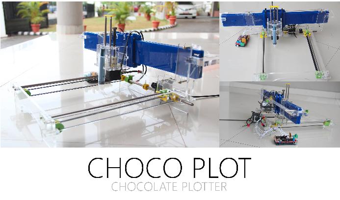
Chocoplot in a glimpse
After having a conversation togeather with all the members we decided to go with chocoplot, Its a 2 axes machine where the end effector will be choclate squeezer,
My Contributions.
I was in charge of assembly,worked on salvaging and sourcing materials needed for the project, created and styled the team website, and also played a major role within the end effector design team.
Our mentor gave us a challange for this week that is not to buy any materials from market other than 100% fabable material or salvaging was the only option he gave for us ,i am assigned to source materials
Sourcing Materials
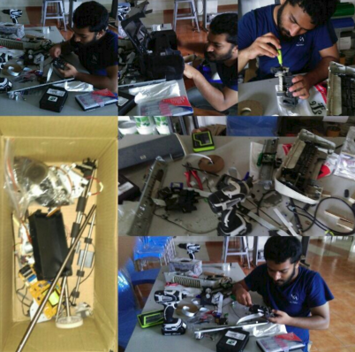
me along with my friend left to the place so called 'chaala' (reknowned for e-junks) which is 14 KM away from my place and i have predetermined idea to get what all scraps to get,
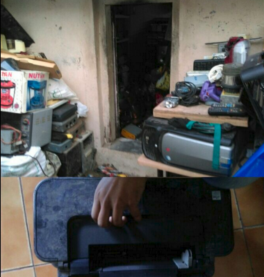
the main part we need to salvage is that the threaded rod so decided to get old printers so that i can get threaded rods and belts.damn!! some printers did'nt have these rods ,it has got another mechanism with plastics. so wandered pretty long for needed printer, anyhow managed to get required printer.using hammer,mallet,drillers and screwdriver managed to seperate parts and grab required materials from it
- Threaded rods
- belts
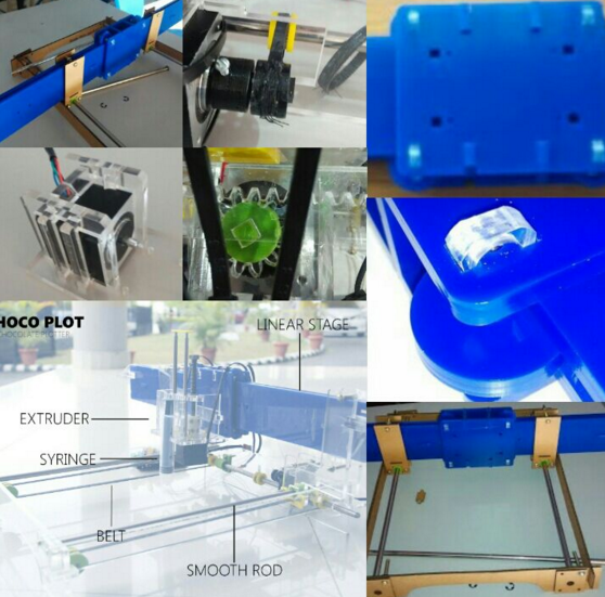
Assembling
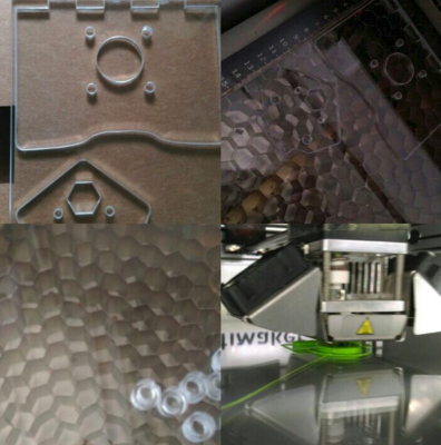
designer team handed over files and rest was my job most of the time, like laser cutting and 3d printing was the main job i have done so far,i will do the operation required and put into a shape,since we have many press fit designs putting it together was my job for most designs,some of the designs needed much of effort to get it right..used file to grind the edge down
Documenting
I am in-charge of team documentation,we have shared a common pad everyone update their contribution and i used to check frequently i will correct if any mistakes and align then fit under proper heading adn then will push to the repo, i used minimal html and css styling, what is the issue was i had to check frequently that anyone updated also we adopted this method inorder to avoid the overlapping of the same fragment
End effector contribution
yadu was the one who made the basic design and puneeth made the x direction mechanism.Here me and yadu was assigned for the end effector mechanism
This 2 weeks i have learned more about the 2 axis machines,in depth working principles,types of movement can be given to the X and Y axes.also was like a research for me
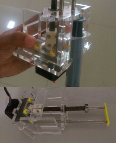
Making an holder for End effector
Building a base plate
i decided to make a base plate where i can adjust the z axis based on the size of the cake it can adapt the base accordingly,started designing in rhino
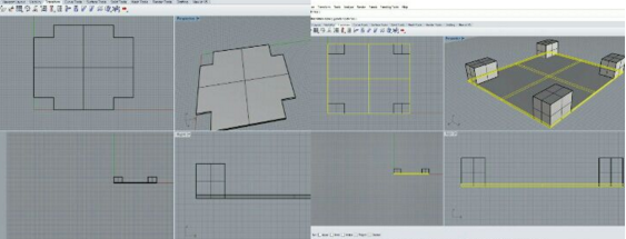
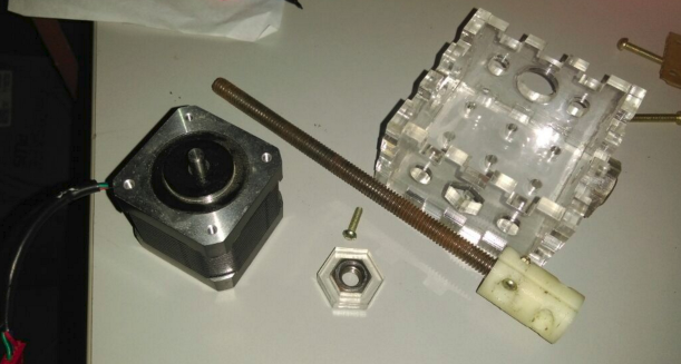
imported the Nema-17 and also threaded rod to rhino
Managed to draw design which look like this here the base of the chocoplot will be placed on the stand provided and only the plate will move to and fro based on size of cake and purpose here the baseplate will be slightly bigger than the chocoplot machine inorder to hold it without interfering its freedom of movement
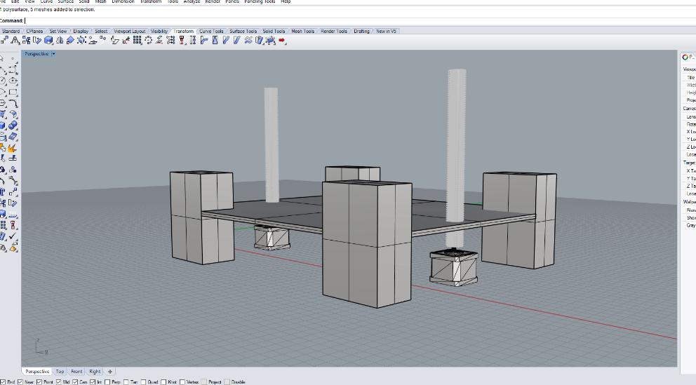
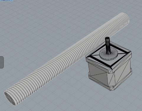
Here goes the 3D view of the same.
Trying it out..!
These are the materials i choosed to test it out,these are unwanted pieces of projects i brought it together to test my plan
What is stepper motor?
"Stepper motors are DC motors that move in discrete steps. They have multiple coils that are organized in groups called "phases". By energizing each phase in sequence, the motor will rotate, one step at a time. With a computer controlled stepping you can achieve very precise positioning and/or speed control."
Here i am using Nema-17,which has the following specification:-
- Four phase
- Unipolar
- Permanent magnet motor
- 200-steps-per-revolution
- Dimension:1.7 in. square footprint, 5 mm shaft diameter
- 12 V power
for the design i have imported the nema 17 mesh which i get it from Here
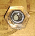
On a piece of cardboard i made needed hole in the centre also glued the piece of acyillic in which the threaded rod fits fine it.
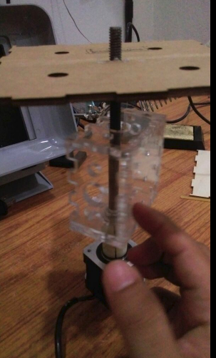
when connected the baseplate with the stepper module it looked like this:-
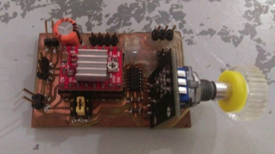
This is the stepper driver i am making use of which is customized "A4988" board,a complete microstepping driver with built-in translator for easy operation.Operates in bipolar stepper motors in various step modes which include full,half,quarter,eighth, and sixteenth with an output drive capacity of up to 35 V and 2 A(plus or minus).
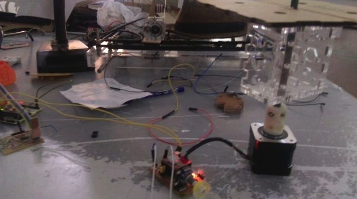
This is the image shows the representation of the baseplate working
this video will depicts the rotation,in either direction also can vary speeds
This is currently used but its working and all done just need to cut and assemble will look into it once done with the rest of the parts
You can download my design files HERE..!