Week 12: Output devices
Introduction
This week i want to create a microcontroller board and to connect an output device, with in our lab inventory itself i have many options like RGB LED,LED array,LCD display,speaker and varieties of motors like servo,brush dc,brushless dc,stepper etc.within the output devices it can further classify it as
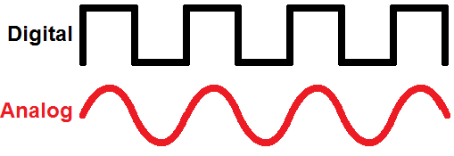
- Analog
- Digital
Analog output devices are such devices which can be varied instance to instance
Electrical signal that is converted into a pattern of bits which is discrete
I am going to choose servo motor,which come under analog
What is a servo motorA servomotor is a rotary actuator or linear actuator that allows for precise control of angular or linear position, velocity and acceleration. It consists of a suitable motor coupled to a sensor for position feedback.
here i am using "model number of servo" 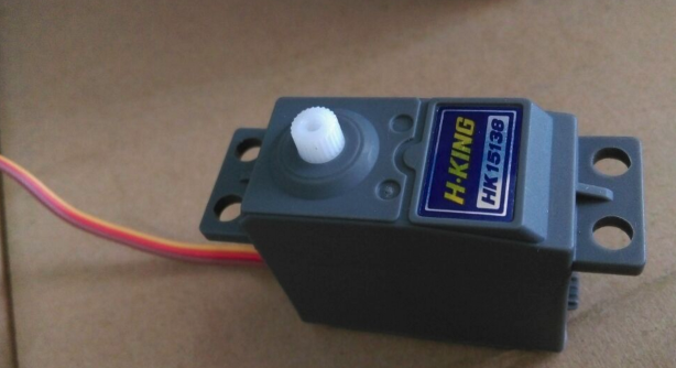
- Torque (@ 4.8v) : 3.8kg
- Speed (Sec/60deg): 0.17
- Voltage : 4.8v~6v
what is inside a servo?
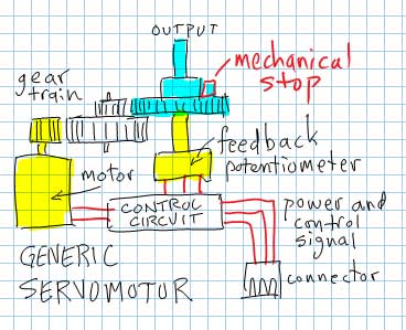
As it is clear on the image the main parts inside the servo is motor,controller board,gear train and feedback pot.The controller co-ordinate the rotation by processing the PWM signal,also its clearly noticable that there are mechanical stops on the servo to limit its rotation by 180 degree,that may be on the gear on elsewhere
Servo works on PWM (pulse width modulation) which means that servo is controlled by digital signals with varying width of the pulse
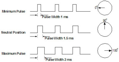
One of several ways PWM can be produced is by using a sawtooth waveform and a comparator. As shown below the sawtooth (or triangle wave) need not be symmetrical, but linearity of the waveform is important. The frequency of the sawtooth waveform is the sampling rate for the signal.
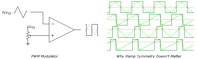
The limiting factor of the speed is comparator's frequency response.
Design
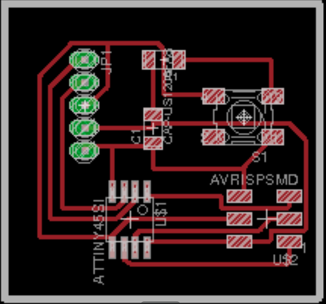
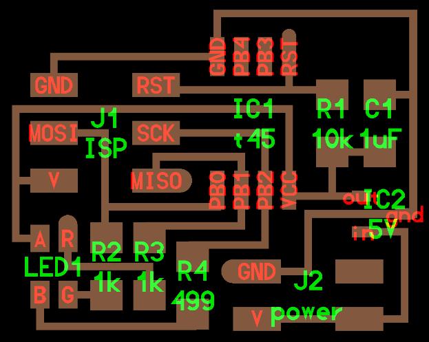
Now i wanted to design a circuit board for controlling servo , i am choosing Attiny45 since i only need few pins,this is the design of the circuit:-
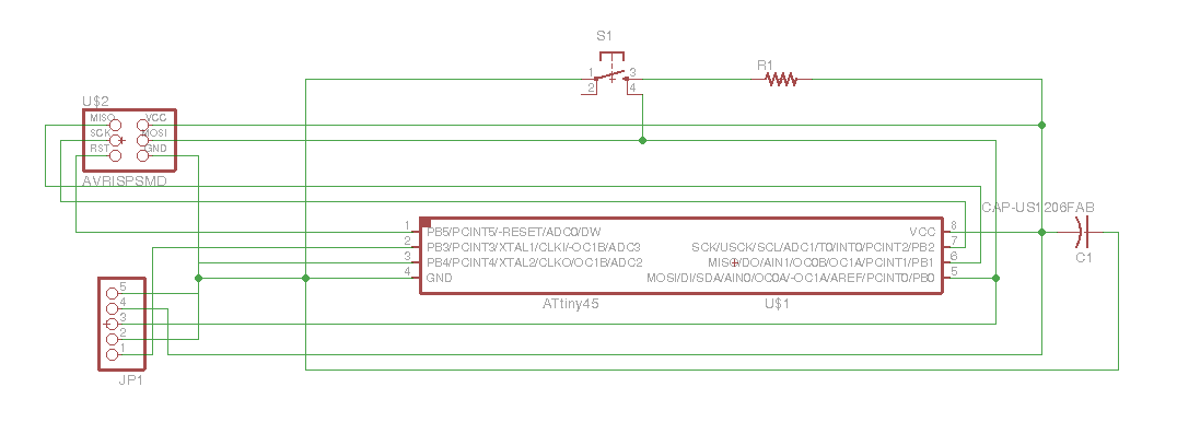
here goes the schematic of the circuit
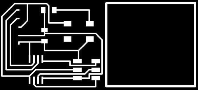
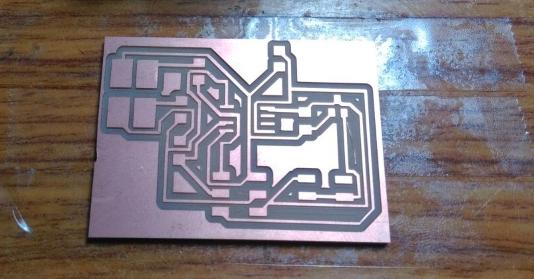
Here goes the monochromatic image which is ready to go,
Here my circuit is very simple since its only need one PWM pin to control the servo,since i am using attiny 45 it has got 2 PWM pins, which is pin0 and pin1
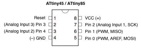
In case we need more than 2 Pwm ,we can make your other pins pwm using code,so called software PWM
// code for ATtiny

// fades LEDs on all five pins on and off using software PWM

#define fadeSpeed 20

void setup(){

for(int pin=0;pin<5;pin++)

pinMode(pin, OUTPUT); }

 void loop(){

 for(int pin=0;pin<5;pin++)

 {

for(int fade=1;fade<254;fade++) { //fade on softPWM(pin, fade, fadeSpeed); } for(int

 fade=254;fade>1;fade–) { //fade off

softPWM(pin, fade, fadeSpeed);

}

}

}

void softPWM(int pin, int freq, int sp) { // software PWM function that fakes analog output

digitalWrite(pin,HIGH); //on

delayMicroseconds(sp*freq);

digitalWrite(pin,LOW); //off

delayMicroseconds(sp*(255-freq));

}
The credit of the code snippet goes to Ernst Christensen
making
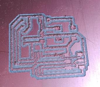
as seen on the image the traces where not fine because of the bad milling bit(maybe edge of the 1/64 bit is broken), when i rubbed it with a rough cloth it went fine all copper grains are removed
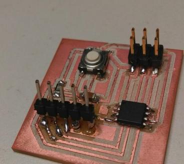
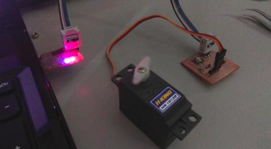
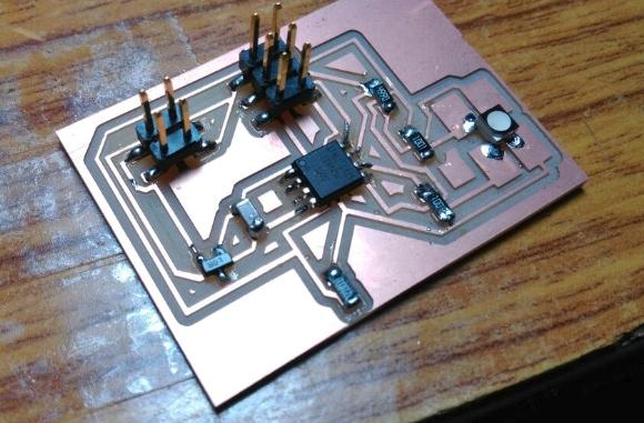
once i am done with stuffing,checked the board,bootloader burned to test microcontroller status,everyting ok.then i connected the board with an isp and servo is also attached
I used Arduino IDE for programming an d managed to write the code
--code for servo --
                /*

                 Code for servo control

                 Nadeem Ahmed


                 #dc4s1


                */


    #include <SoftwareServo.h>

int pos = 0;

SoftwareServo myservo;

#include <SoftwareSerial.h>

  void setup()

  {

 myservo.attach(0);

 }

 void loop()

 {

 for(pos = 0; pos < 180; pos += 2)

 {

 myservo.write(pos);

 delay(15);

 SoftwareServo::refresh();

   }

 for(pos = 180; pos>=1; pos-=2)

 {

  myservo.write(pos);

 delay(15);

 SoftwareServo::refresh();

 }

   }
Here goes the working video of the servo:-
You can download Files here.
Trying Out RGB LED
Since i got time this week i am going to try out the RGB led out of curiosity
Specification
- Color:Red, Green, Blue (RGB)
- Current - Test:20mA Red, 20mA Green, 20mA Blue
- Height (Max):1.90mm ~ 2.10mm
- Mounting Type:Surface Mount
- Package / Case:4-PLCC
- Packaging:Tape & Reel (TR)
- Size / Dimension:3.20mm L x 2.80mm W
- Supplier Device Package:4-PLCC
- Viewing Angle:115° ~ 120°
There are three major groups of RGB LED's: dichromatic, trichromatic and tetrachromatic.
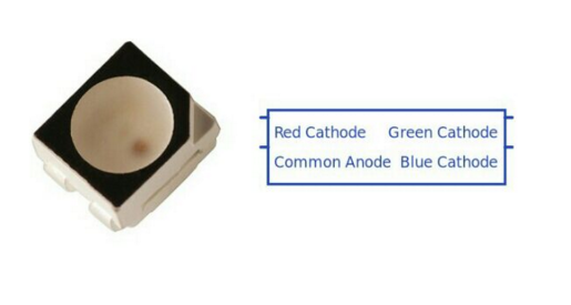
Here i am using RGB led plcc-4I took neils design and redesigned it as show how it is done,This is the neils design
Niels
Schematic
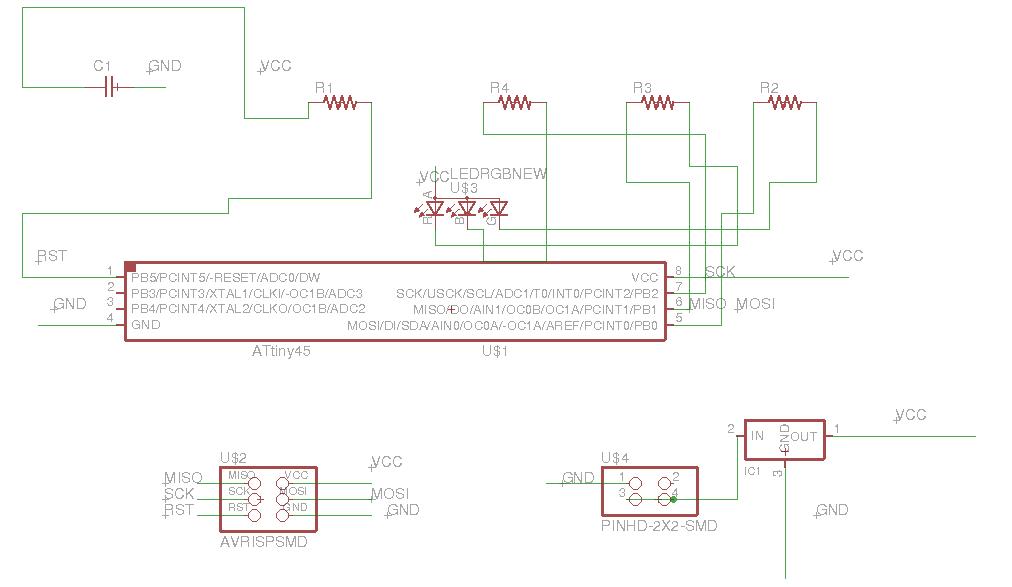
Redesigning starts here with the help of the prior design image i was able to understand the conncetion between components so i mapped the same to a schematic
Trace and cutpart
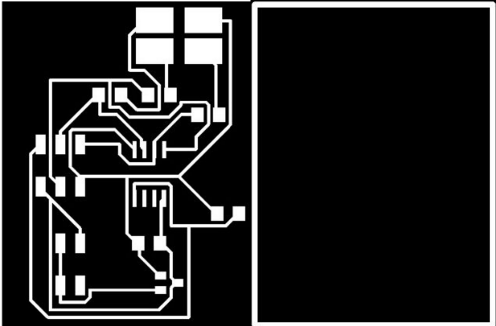
Monochromatic images which is i used to mill it in modela,donot use this for milling since its a editted image i am keeping the original files within here.
Milled
Stuffed
Checked the connection all good to go now need to program the same in the code we have to specify in which pin is r g and b is,otherwise the combination of the colour we code will change and wont obtain desired colour,Things to keep in mind is that the notch seen on the LED should be matched to "R" plate.
Code
int redPin = 1;

int greenPin = 2;

int bluePin = 0;

#define COMMON_ANODE


void setup()

{

  pinMode(redPin, OUTPUT);

  pinMode(greenPin, OUTPUT);

  pinMode(bluePin, OUTPUT);

}


void loop()

{

  setColor(255, 0, 0);

  delay(1000);

  setColor(0, 255, 0);

  delay(1000);

  setColor(0, 0, 255);

  delay(1000);

  setColor(255, 255, 0);

  delay(1000);

  setColor(80, 0, 80);

  delay(1000);

  setColor(0, 255, 255);

  delay(1000);

}


void setColor(int red, int green, int blue)

{

#ifdef COMMON_ANODE

    red = 255 - red;

    green = 255 - green;

    blue = 255 - blue;

  #endif


  analogWrite(redPin, red);

  analogWrite(greenPin, green);

  analogWrite(bluePin, blue);

}
Here goes the video of the RGB led
You can download Files here.