My final project
About my final project during my fab expedition

zezo to chickzaw
My first thought on project was to make a microbot, what i wanted is to integrate sensor to a fully packed little tiny bot integrated with customized fabduino. Planned for a bot where it can fit almost everywhere who can sense the current status of the medium he is occupied and also so to retrieve the same data to our mobile device.which can be used in many situations in engineering,medical,astronomy and construction based on the nature and design i am going to give to zezo, we can integrate features based on the need of zezo.
A 360 degree rethink!

Decided to change my project and to make a useful one.I love pets, and i have a chicken coop i decided to transform the normal coop to smart and customized.
Thinking of switching chicken coop with some features embedded.- Automatic feeder system.
- Automatic water dispenser.
- Egg collector and Notification system.
- Predator alarm mode.
Coop will be made with (plywood)shopbot and mesh,will use custom designed boards as controller will develop a mobile phone application in which user can check the status like which mode currently coop is in,can also switch to predator alarm mode.First i thought of GSM module as transmission medium then switched to bluetooth.will use 3d printer and laser cutter for feeder system designs, The feeder system with auger and servo .IR sensor will be used to sense the egg and miss call notification system with gsm module each time when hen layed egg.since i am planning a slanded base with some comfortable degree to chicken where the base will be mesh,so can collect the egg to egg tray
what will controller do?
- control and feed food timing and quantity.
- control water flow.
- sense egg and send notification.
- sensor value processing for predator alarm mode.
Machines making use of:
- Shopbot
- Laser cutter
- 3d printer
- modela
- roland vinyl cutter
Bill of materials:
- Plywood
- Acrylic
- controller
- attiny 45
- pin header
- IR module
- Auger
- pipe(3/4 inch,level tube,1/2 inch horse) and T-joint(3/4 inch)
Things to do..
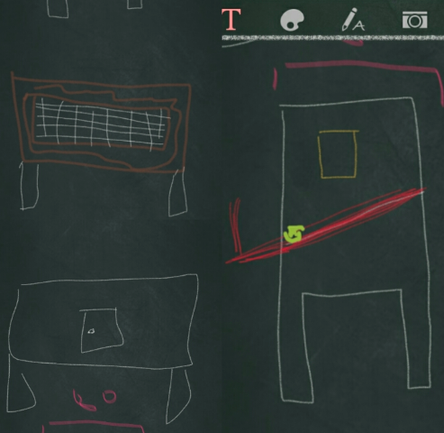
This is the primary rough sketch i made in my mobile application (htc scribble) which made the base skelton idea for my project
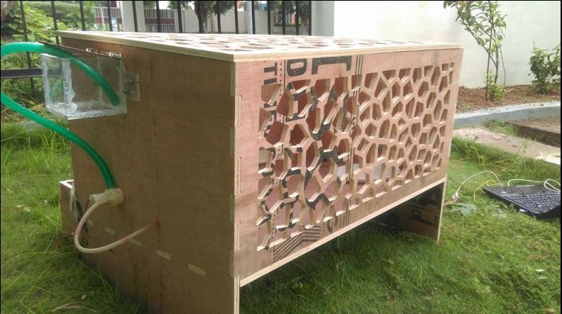
I have made much consederable changes from the start to the end of the project,i planned to use mesh first of all then designed the fabable design so called voronoi structure, which looks like assymetric honey comb mesh
Making
1.shopbot(wooden skelton)
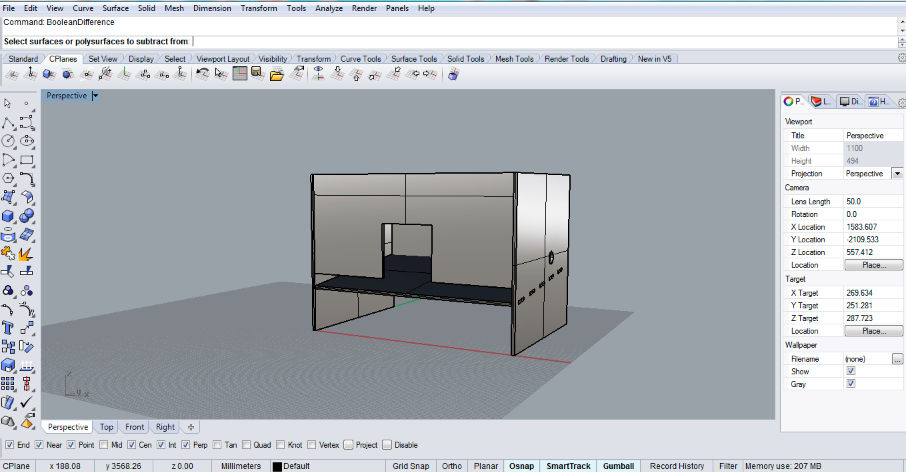
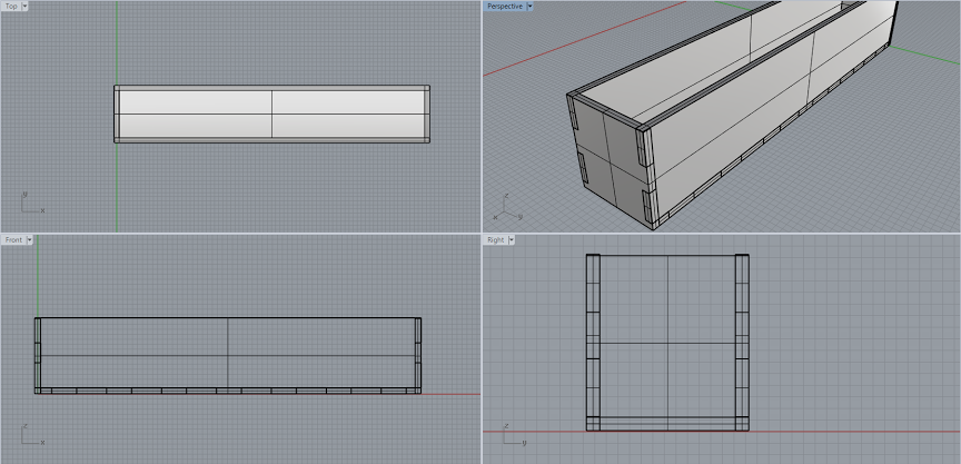
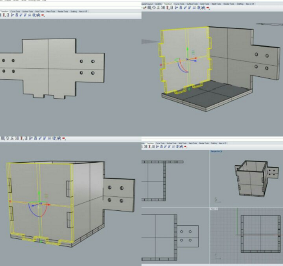
The main visible part of my project is the wooden structure for the same i have designed it in Rhino with the help of grasshopper.Here goes the basic design
design parameter i followed
- Material extrusion: 12mm
- Pressfit tolerance: 5mm
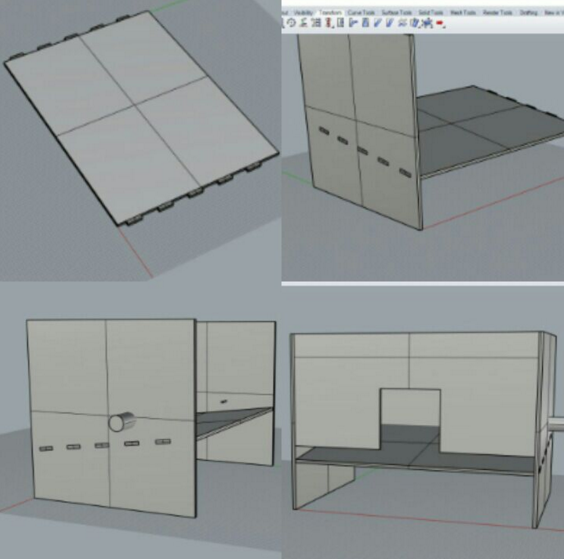
Here i used tolerance as 5mm so as to make pressfit firm and tight, also my plywood was not even on surfaces so have to change the design accordingly on material quality and consistancy, the below image represent various processes of designing the coop design.
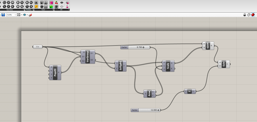
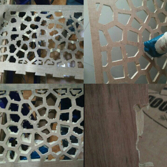
As i planned to pin mesh to coop so as to provide necessery sunlight and airflow,but i planned to design unsymmetric honey comb mesh so called voronoi.for the same i jumped into Grasshopper in rhino 3d .To be frank it was a mess when i did it for the first time and i felt a bit slow when we map the function to respective curves or sufaces in grasshopper
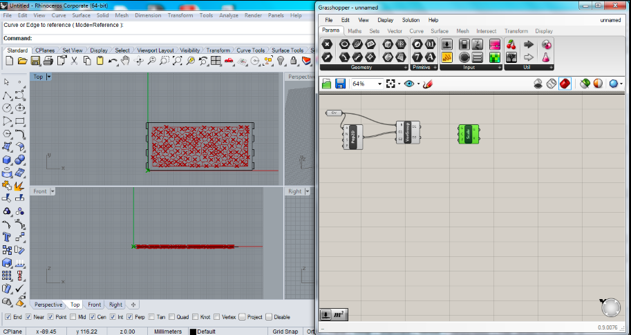
The below image is the exact functionalities needed to create a voronoi structure
Grass hopper design filesHERE..!
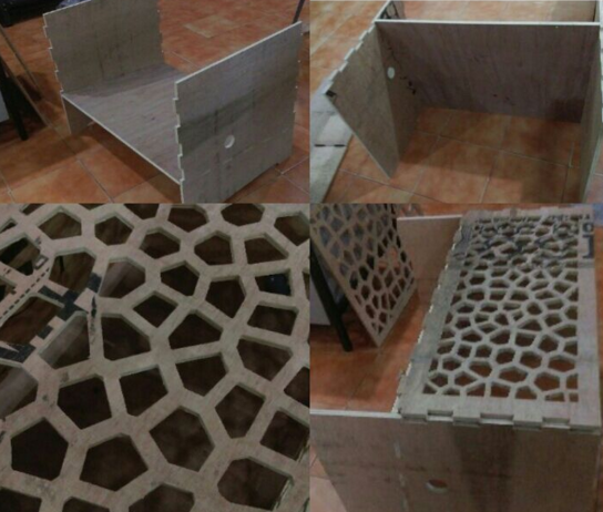
such a way i have made my 2 piece of wood into voronoi, the upper part and front part
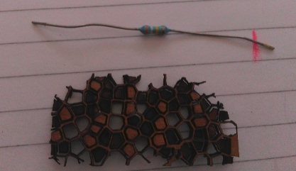
This image represnets the test cut of the voronoi structure i made in laser cutter on cardboard,here the size is small since its scaled down version of my design.
Milling design in shopbot
All design set to mill,Using Vcarve. I have arranged the work on the ply such a way that it fits exactly i used a entire 8ft x 4 ft and an additional piece of 80cm x 80cm for a single workpiece.I have generated vcarve files.by keeping in mind the below given common facts:-
- Bit using
- diameter of the bit that can fit in so as to make edges.
I used the below setting for milling my design
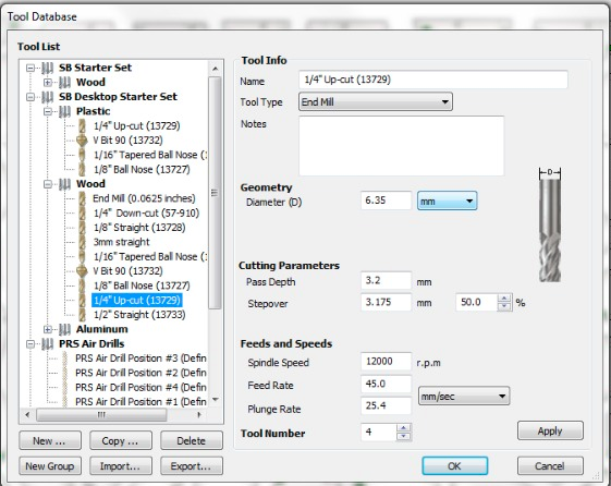
Here the Spindle speed is 12000 RPM and plunge rate is 25, feedrate is 45 and pass depth 3.2 also i am using 1/4"upcut and 1/4"ballnose upcut for engrave and pocket
Loaded the material on shopbot and ready to go..!
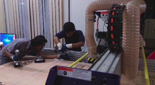
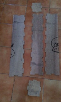
These are the cut pieces shown in the image.the last row of images are voronoi structure's
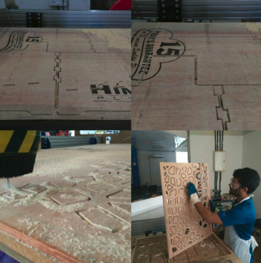
with help of my mates i have managed to assemble the same,used dremal and file to sooth exposed edges and tab remains etc.
video showing the cutting of voronoi structure.
Almost done with the coop structure now have to design a haybox(egg collector box) i have used rhino for this as well
 milled the design in shopbot turned to cut the haybox parts the image shows the haybox assembly.
Error and fixes
Due to uneven surface of my plywood ,it has got bend.since i gave the cut depth as 12.5 mm eventhough the material thickness is 12mm i didt got the cut well so needed much effort on filing,became a filing expert though.Used dremal and file to resolve the same.
Mission accomplished
ACRYLLIC BOXES
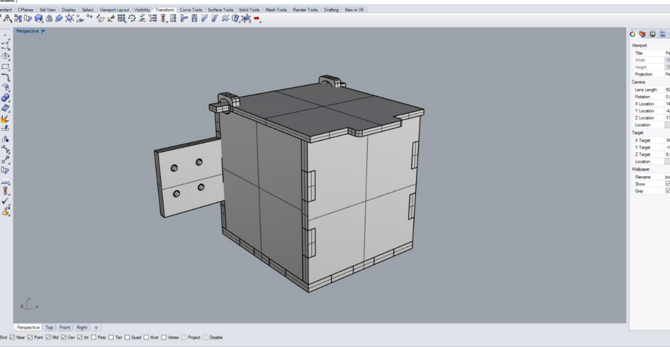
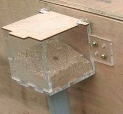
I need a simple pressfit design,the purpose is that to use as container box for food and water.i will use 6mm clear acryllic so that we can understand the quantity in it without opening and i ma using craftwood as top since we have 3mm craftwood inorder sooth the opening and closing.I started designing in rhino,i have left some extra material that lean to both the sides with screw holes,i measured my screw diameter with vernier calliper so by keeping an tolerance i can keep holes on the material
and finally made a design that looks like this:-
 2D- final part
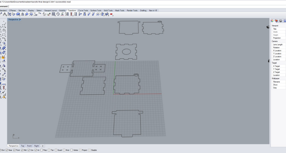
Before cutting i planned to do a test cut so i made test design with all possible dimension to see which fits better,here is the piece i used to test with 20mm length
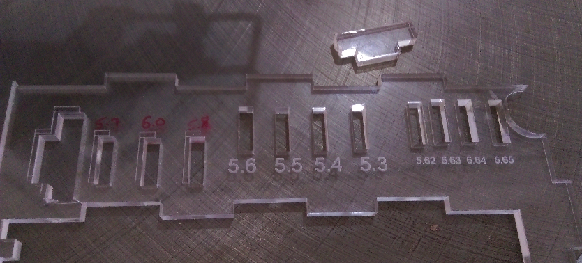
This helped me alot to keep the pressfit exactly how i wanted so that i can make adjustments in my design
Here is the final design which is mounted to the wooden structre.
Auger design and 3D-print
PURPOSE: Used to sweep out the feed in pipe that is connected to the storage container
Here i need auger shape where its base is connected to servo motor,started designing in rhino it did'nt took much time to design the same a single "sweep 2" did the job i have kept a "+" shaped depression on the base inorder
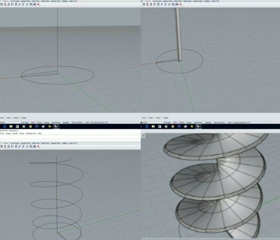
Here is the finally printed auger ->All good
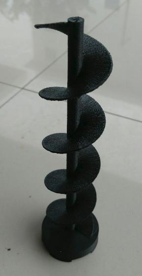
i dremelled the base to increse the depth of the depression.
Now i wanted to attach it to servo ,but i dont have a continoius servo which is compulsory to make a feeder ,which is not in our inventory so when i checked local market its not available also online websites which will deliver in 2 days only got high torque servo which is expensive and wil take minimum of 2 days to deliver so planned to make the existing servo continous,that was a try..!
Making servo continous
I took the normal servo and removed all screws then desoldered so that i can see whats inside, and then Pulled out entire components inside it.this is how it looked
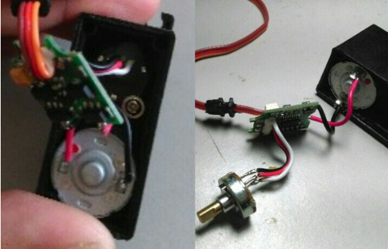
Then on the other side where rotor spindle is found another set of screws ,opened the case where gear are placed,from the below image there is clearly visible mechanical stopper in the gear train.
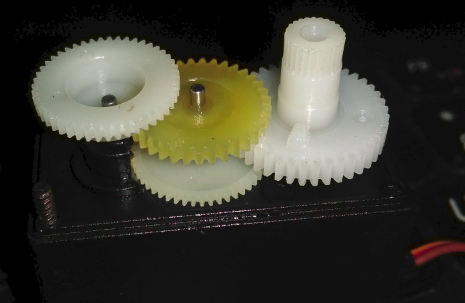
Using Dremal tool i sliced it off, once done i checked the rotation ,even now its only 180 degree max.when i searched found that inside small metal casket found where feedback potentialmeter is connected to which prevent the rotation now.By the time ii noticed my friend sibu working on EDM (Electrical Discharge Machining) prototype for his final project
Decided to use it to cut a narrow piece first with dremal i have made it thickness to so thin,This is the video showing the process
Hurray.. its rotating in 360 degree, i have done with all mechanical stopper did'nt know any electronic or software limitations is there so i connected my servo board t hat i made in output week and tested, all fine
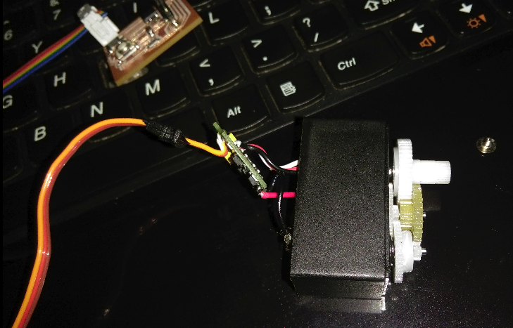
so attached the auger made to the servo and tested the same ,the below video shows the working of servo with auger attached
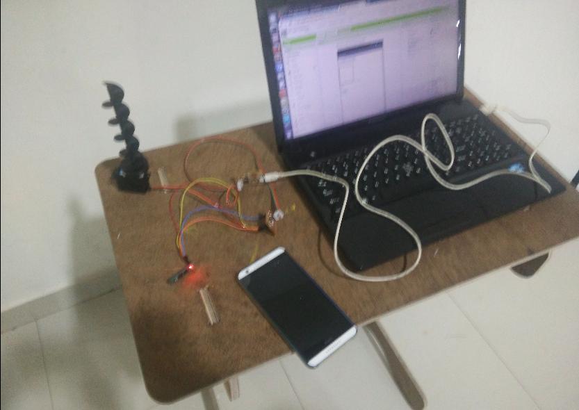
Getting into Electronic part
- Controller board
- Servo
- IR
- Water dispenser
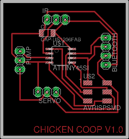
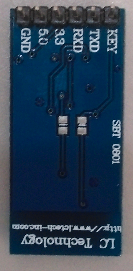
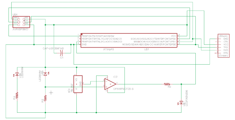
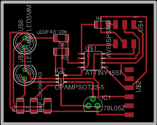
For controlling and co-ordinating all the operation in the chicken coop,which in the fisrt stage include servo control,water pump control and ir module later on i had to add camara and thermal scanner etc.So first i decided to make it my own,when i searched alot satshakit striked me, satshakit micro will be more than enough for me .But anyhow decided to fabricate mmy own small board using attiny 45 where i have to connect servo motor,dc pump,ir module and bluetooth for interfacing.started designing in eagle and the schematic is as shown here:-
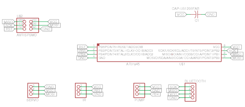
Here goes the design of the board
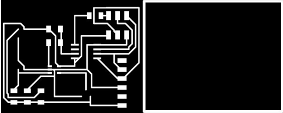
Trace and cutpart
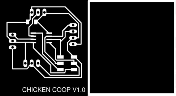
Downlaod filesHERE..!
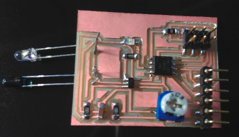
milled
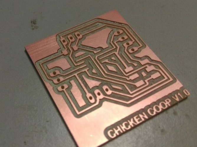
stuffed
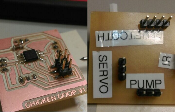
All "GOOD" to go..!
Application Interfacing Using bluetooth
This part will bring the smart coop a bit smarter,since here is where i am enabling the user to access the coop remotly.
This is the bluetooth device i used for my coop where i will make use of only 4 pins which are VCC,GND,RX and Tx.
(APP INVENTOR)
Here i am using MIT app inventor to craete my application used for the interfacing of the device with the mobile application,which follows scratch based developing platform managed to drag the blocks as shown in the image for my functionalities
Once authenticated goto Projects -> Start new project and its done ,ready to go! Its very easy to use ,just drag an drop what all functions we need simoultennously we can see the screen and once dragged everything needed.have to switch to Block view
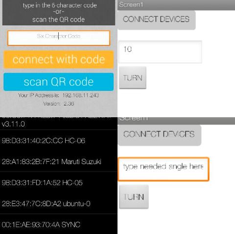
This is the screenshot of the end user applciation made for controlling the chicken coop, here its showing the feeder control
As i did it the same in my interfacing week its all fine,and did'nt have to invest much time on it since all worked fine.
Water dispenser
What i wanted is to connect a water dispenser to my chicken coop so as to control it in mobile,for the same i used 12V DC pump which is attached to the water container
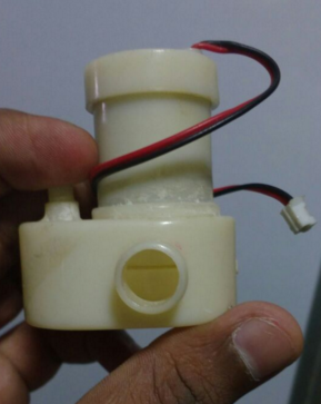
plan is to connect this pump with some motor driver and use MIT app inventor application to drive the same.
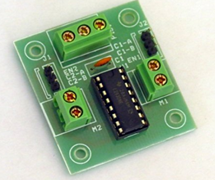
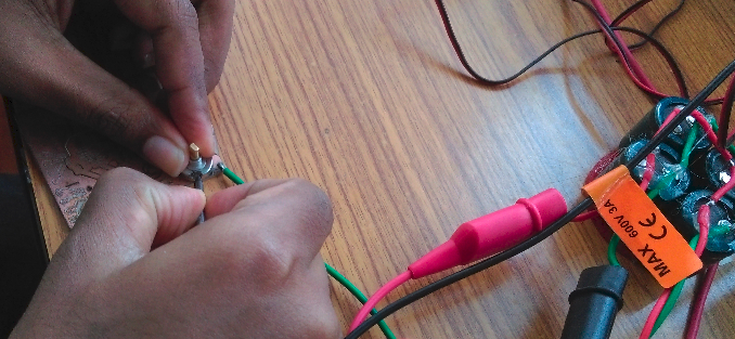
i used L293D motor driver IC module which is typically used to drive motors in both the direction since i have same functionality i will be using the 16-pin board to drive my 12v DC pump here.So in the code i have to just enable the pin high when invoked.
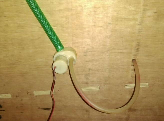
Here goes the pump attached to the coop where one end is left inside the coop for replenishing the water bowl inside and the other is connected to water container.
What i will be modification if i build it for next time?
For the water container acryllic press-fit container whcih is ok, but i used glue gun as seal for not to ooze water out it was partially success but inorder to make it cool i will use Silicon sealant
Egg counter
I wanted to attach a small Egg counter module so as to count the same and display it on my mobile phone,i used the below logic for designing the IR ciruit
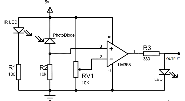
Designed in eagle with modification and adding the isp and pin headers to the circuit,This is the schematic of the circuit design
Board design
This is the stitched image of both trace and cut part, Note: please do not use this image for milling i am including the orginal files that is not edited and ready to mill.
This is how it looks ,the board i fabricated
sadly this board is "NOT" working as i expected to be i have put some time on the board but i was not able to do it, the deadline for presentation is approaching so i switched to use a IR module so as to connect it to my controller board, i will on my board after this tight schedules i have.
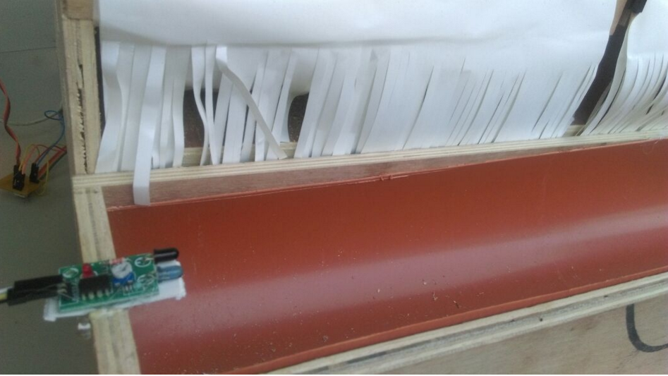
The module is working fine for my counting functionality
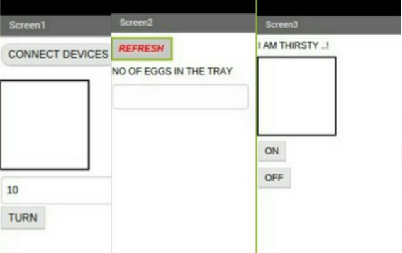
This stitched images represents UI of all 3 functionalities ,that is servo,egg counter and water pump respectively
Code everywhere..!
#include <SoftwareServo.h>


int pos = 0;

SoftwareServo myservo;

#include <SoftwareSerial.h>

   #define RxD 3

   #define TxD 4

   #define DEBUG_ENABLED  1

   SoftwareSerial blueToothSerial(RxD,TxD);

   int state = 0;


   int egg_count = 0;

   void setup() {

    pinMode(3,INPUT);

       myservo.attach(0);

     blueToothSerial.begin(9600);

   }

   void loop()


   {

    if(digitalRead(3) == HIGH)

    {

      delay(5000);

      egg_count ++; //increment egge count with 5 sec delay

    }


   if(blueToothSerial.available() > 0){

    state = blueToothSerial.read();

    blueToothSerial.write(state);

   if(state >=0)

   {


    for(pos = 0; pos < state; pos += 2)  //rotate continious servo

  {

    myservo.write(pos);

    delay(15);

    SoftwareServo::refresh();

  }


        }

   else if(state ==0)

   {


     blueToothSerial.write(egg_count); //counts egg

   }


   else if(state ==2)

   {
    digitalWrite(4,HIGH); //Pump ON

   }

   else if(state ==3)

   {
    digitalWrite(4,LOW); //Pump OFF

   }


   }

   }
Improvements i could make !
There are point of improvements i could note inorder to make the next one to the next level that include a nice custom made application which will provide nice UI and UX to user, also i will improve on food container design and coop's door part.
Future and Scope
This is the begning only i have alot plans for my "S(mart)-COOP" the plan include to embed the following features
- Predator alarm
- Cloud integration
- Status reporting
- Automatic Door opening and closure with conditions
- Self cleaning
- Monitoring mechanism
Here goes the S-COOP like a boss