Week Eight: Embedded programming
Reading Datasheet
This is Attiny datasheet
what i learned out of analyzing a data sheet?

The first thing i noticed when i opened the datasheet is this pinout i saw some unknown words like PDIP,SOIC,QFN,MLF,VQFN. so i started reading it about a bit its abbreviations itself will explain what it is
- PDIP -> Plastic Dual In-Line Package (Through hole mount)
- SOIC -> Small Outline Integrated Circuit (surface mount)
- QFN -> Quad Flat No-leads
- MLF -> Micro Lead Frame
- VQFN -> very thin quad flat no-lead
- Internal Clock the Internal Oscillator provides an approximate 8 MHz clock. Though voltage and temperature dependent,
- External Clock: on user discretion and type of Program
- 20 Powerful Instructions - Most Single Clock Cycle Execution
- 32 x 8 General Purpose Working Registers
This link help to grab abbreviation of almost all packages
Packages
we know that there are 14 pins in total for attiny 44 and in that one is VCC and the other ground the rst is 12 data pins which include the pins included for programming(MISO, MOSI etc.)
The datasheet reminds me of my MBD(Microprocessor Based Designs) textbook, i understood that i cant grab all the things in a glimpse so what i am doing is i will list few basic features:
Clock :
RISC architecture : ( Reduced Instruction Set Computer ) The general concept is that of a system that uses a small, highly optimized set of instructions, rather than a more versatile set of instructions often found in other types of architectures.
8 bit microcontroller : 8 bit microcontroller means CPU or ALU can process 8 bit data at a time. Means it has to take 8 bit data from memory (which it has to process). Thus each location in memory is 8 bit and data bus is also 8 bit. Registers in RAM has to be 8 bit for temporary storage of results.
Register:
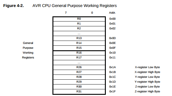 Discrete memory locations within the CPU used to hold temporary data and instructions
Started playing with Arduino IDE
Last week i have made my own hello board with little customization that include 2 LED and 1 switch, so this week am going to play with the same and make it BLINKKK!! I have installed comabatible version of arduino IDE
for programming i have two options,- Fab ISP ( my own :-) )
- Atmel ICE
I will choose ISP, and last week i just made the board echo.hello.isp Now i will get my pc ready what all i need to run the board
- avrdude
- AVR gcc
In a glimpse AVRDude is excellent program for burning hex code into microcontroller. USBasp is awesome USB based programmer for the AVR.We can install Avrdude with.
apt-get install avrdude
to install avr gcc:
sudo apt-get install gcc-avr binutils-avr avr-libc
what is avr gcc?
This tutorial helps me alot in finding the constraints
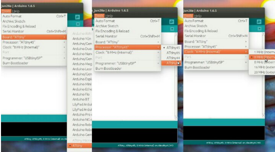
Arduino IDE setup
To add our board in the list
goto preferances ->Add Attiny git library link to the field "Additional board manager URL's:"
and its done now we can see our board in Tools->Boards clock,Now have to select port from the tool menu itself, My programmer is Fab ISP that is "Tinyisp" have to burn the attiny 44a with Bootloader by simply selecting the bootloader menu from the tools.
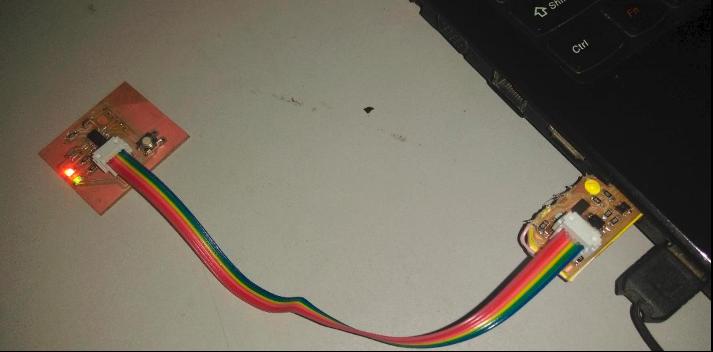
i have connected the hello board to the system using my isp
What made me mad?
I thought that the Attiny pin and arduino pin was the same ,and recognized it NOT!
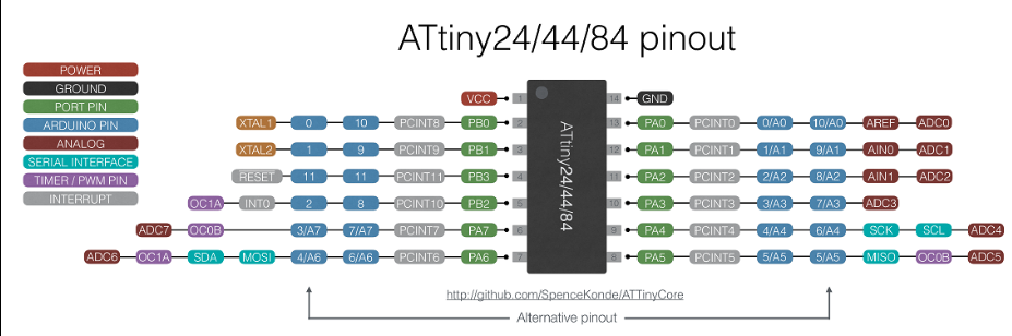
Now i will use blink program for testing the board, the code of program is as follows , according to the design the LED IS ON PB7 AND PB2 th pin of the microcontroller
/*

  Blink Program

  Nadeem Ahmed

  Fabacademy


 */


// the setup function runs once when you press reset or power the board

void setup() {


  pinMode(7, OUTPUT);

  pinMode(8, OUTPUT);

  pinMode(2,INPUT);


}


// the loop function runs over and over again forever

void loop() {

int sw = digitalRead(2);

if(sw==HIGH)

{

  digitalWrite(7,HIGH);

delay(100);

digitalWrite(7,LOW);

delay(100);

digitalWrite(7,HIGH);

delay(100);

digitalWrite(7,LOW);

delay(100);

digitalWrite(8,HIGH);

delay(100);

digitalWrite(8,LOW);

delay(100);

digitalWrite(8,HIGH);

delay(100);

digitalWrite(8,LOW);

delay(100);


}

else

{

  digitalWrite(7,HIGH);

  digitalWrite(8,HIGH);

}


}
Error..!

One Led is not blinking according to my program, sadly one of my LED was not blinking,so for debugging the same i have used the big multimeter to check whether its working or not one is ok the other still dont lit up.So ended-up in desoldering the defected led then with power supply i gave 3V+ (lessthan 5V) so came to know that LED cheated me.Placed a new LED and its done!
Here goes the board
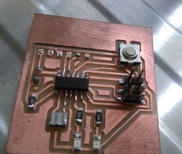
Below i am giving the video in which on press of switch the both LED turns on