Week Seven: Computer-Controlled Machining
This week i am going to play with biggest machine in our fablab "SHOPBOT",as applied to all equipments priority to saftey is very important while playing with shopbot,we got shopbot PRS alpha 96-48-6 which can occupy a maximum bedlength of 2.44m x 1.52m x .15m
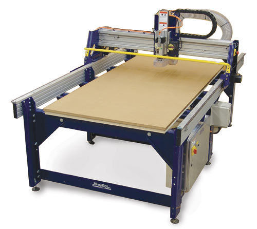
Basically shopbot is a CNC(Computer Numerical Control) machine which is comparitively easy to assemble and deassemble,this machine can be used for various puposes like marking,engraving and cutting on various material spectrum that include plywoods,MDF,wax,metal,bamboo etc.Depending on varying material and purpose we have to be very keen on selecting the 'bits' in our lab we mainly use 12mm and 20mm plywood so 1/4mm and 1/8mm bits are commonly used.
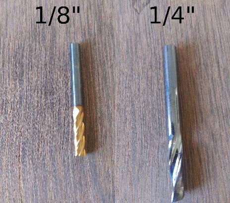
In bits we have many types based on the swirls,no. of flutes and arrangemnet of the bitpattern
- Up-cut
- Down-cut
- Stright
- Compression
What i understood: Stright is basically used as General Purpose Cutting which has moderate chip clearing ability,Sprial Down-cut is used when we need precise top portion of the material, Spiral Up-cut is used for clear down portions,and compression is the combination of down-cut and up-cut bits in spiral fashion which will be good in the case of holes but will have some issues while chipping of the whole ply
Design
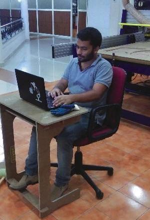
First of all what i have done this week is that i have booked my 'GURU' (@yadhu sharon) for rhino classes,He just introduced me rhino and about most used tools,techniques etc.. with what i got i have decided to make somthing in rhino thinking about the design i thought of a problem that we face in our fablab,Sometime we will have chairs but will run inshort of tables mainly for using labtop,so decided to make a simple laptop holder that can be pulled infront of a chair we got.So i grabbed a measuring tape and started measing dimensions of the chair and required length etc. then made a rough sketch with handi have done 3D 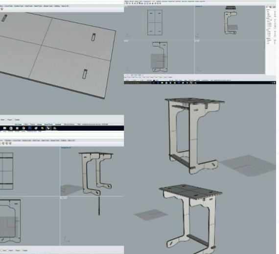
and alligned properly in front view then exported it to '.dxf' file format and opened the same in autocad and made such a way to cut it using the trotec laser cutter and it looks like this:
This was the first design by analysing the same i came to know that this design wont prevail since it lack support to the structures and also found sharp edges are exposed which may harm the user. So in rhino again changed the design and made a final design which looks like this
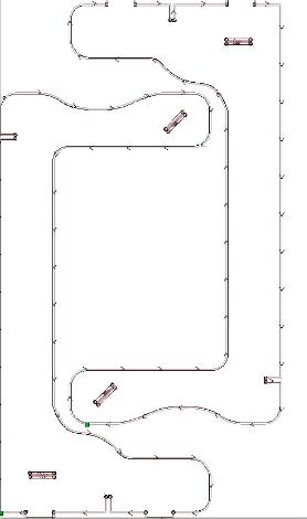
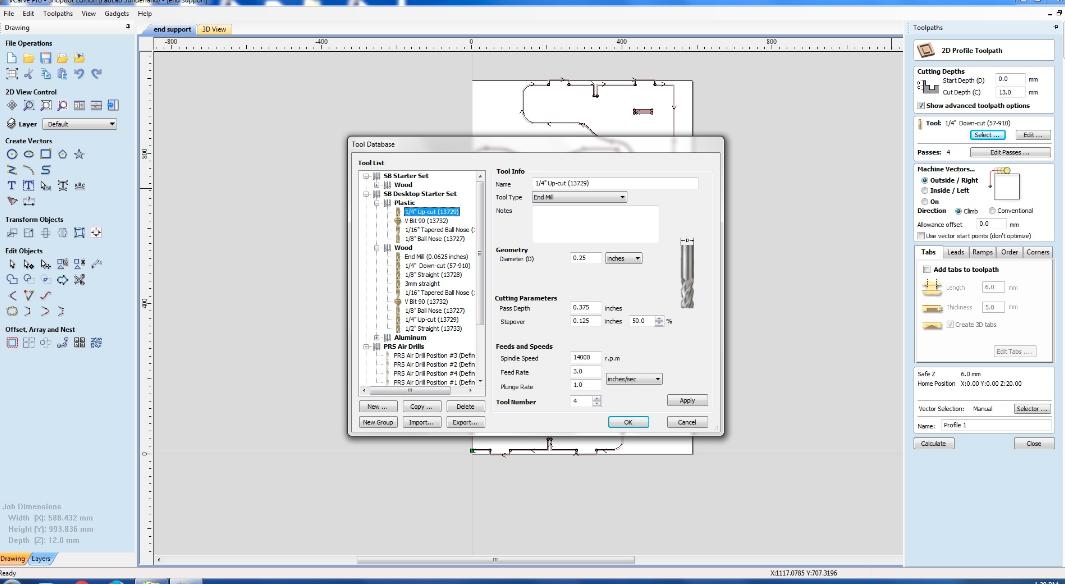
Vcarve : The translator we use for converting our designs to the gcode (".sbp") file which is the only language understandable for the shopbot, This is the basic purpose of Vcarve but here we have other options and a comfotable user interface where we can load images and put it that way to fit best.There is many Functionalities available in the vcarve that include even putting tabs, Deciding where to put screws and also regarding the drill holes.There is specific reason for the importance to keeping the drill holes ,either we can keep circular design on sharp perpendicular wedges or we can put the holes in the vcarve thats given beacuse our drill bit is cylindrical so it cant drill a perpendicular corners 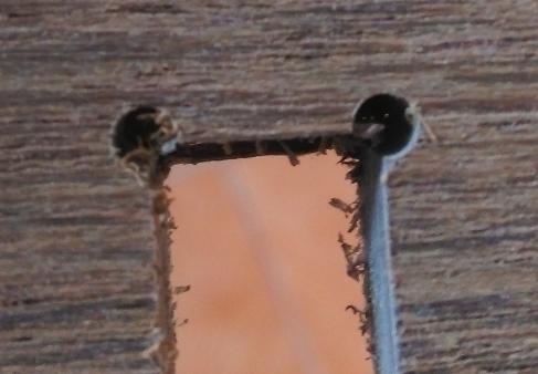
This image explains the need of the curves in design otherwise we wont be able to fit the required piece in its exact place.Vcarve is very helpful for the final patches in the design
Check list
- offset
- drill holes
- profile toolpath
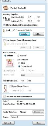 * Cut depth
*which drill bit is used.
Shopbot
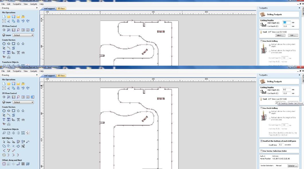
Before milling there are something to be done on shopbot that includes setting the orgin,zeroing Z-axis etc
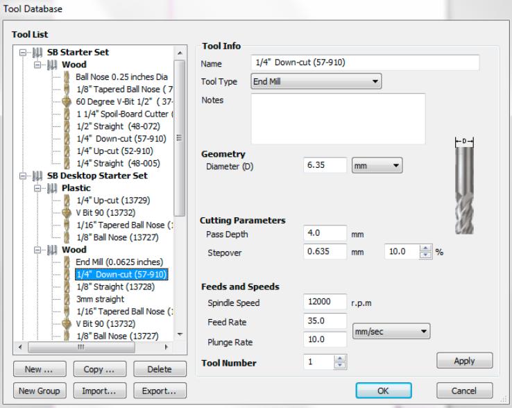
This image explains what all constraints to be taken care of,lets list them and analyse:
- Setting orgin (X-Axis,Y-Axis,Z-Axis)
- Bit used
- Spindle Speed
- Plunge rate
- pass depth
- step over
- feed rate
Fisrt the constarints seen on the images pass depth is the depth that takes in each iteration of the drill, it depends on the thickness of the material and also spindle speed.Spindle speed is the RPM (rotation per minute) measure of the spindle (drill) normally we use 10000rpm,120000,150000rpm which may vary depending on the pupose and material used whats to be noted is that the pass depth will be propotional to the spindle speed.Feed rate is the speed in which the machine head moves in x-axis and y-axis through the work plane its normally 35.00mm/sec .Plunge rate is how fast the z axis can get into.Here tool number is used as the marker for specific drill bit so in case of using one or more bits in the design this tool number will be the only identity that is recongnised by the machine for the drill bits.
Zeroing:setting orgin in x and y, we have to keep the machine in the point where we want to keep the orgin and in the software we have to just select to x and y axis then its done..!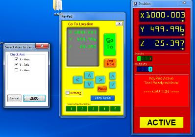
now setting the Z-axis we have a plate attached to set the Z-axis if we choose the option for z axis the spindle module will gear up untill it touch the plate since we attach the plate to the screw , the drill bit stops when it actually touch the conducted plate and its done..!
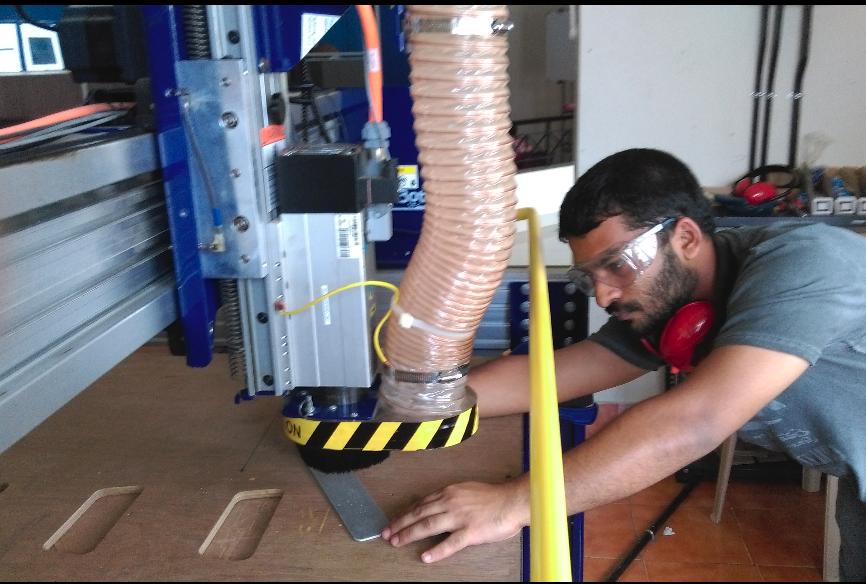
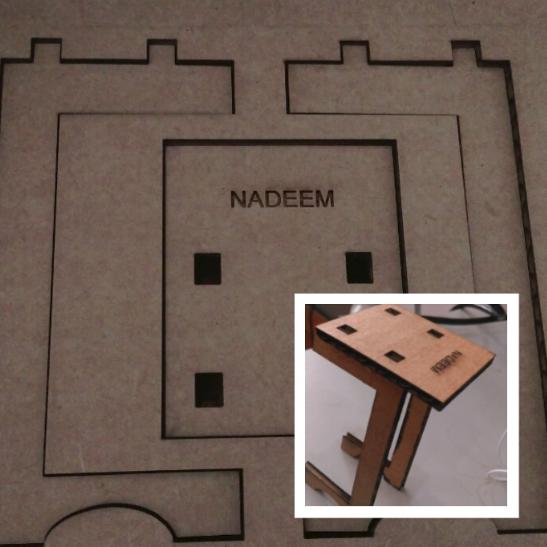
Now i have load the material to the bed,here i am using 12mm plywood inorder to make sure that its fixed well i used clamp and screws we can give screws inside our design too and it can be done in vcarve to allocate slots for the same.since we have done test cut and we got 11.5mm as the best fit measure for the gap to be left in press fits.
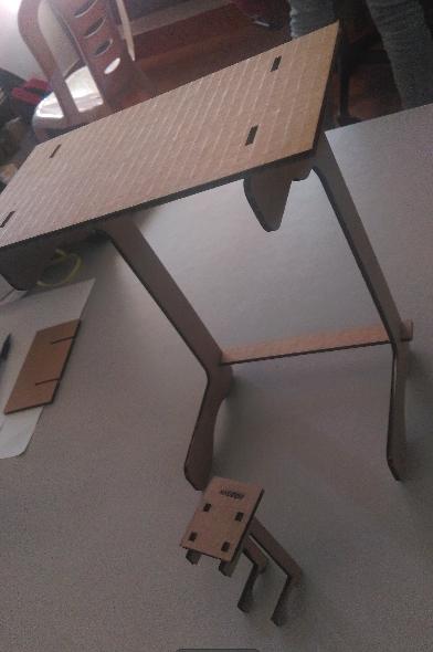
This is what i got after drilling the whole parts
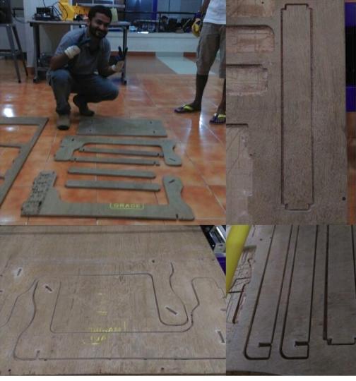
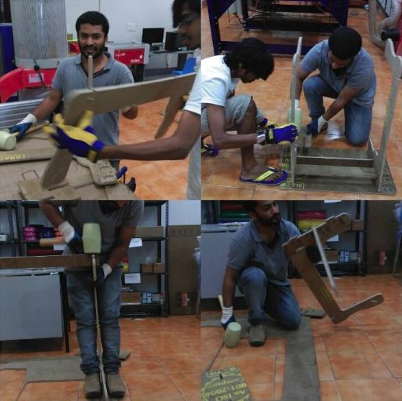
assembling the parts:at some places i had to use file,sand paper and dremal for smoothening the pane.
You can download my design files HERE..!