Networking and communications
Networking protocols
This week mainly i will be mainly reasearching on networking aspects and methods
- Serial
- SPI
- I2C
Process of sending data one bit at a time, sequentially, over a communication channel or computer bus.
Serial Peripheral Interface (SPI) is an interface bus commonly used to send data between microcontrollers and small peripherals such as shift registers, sensors, and SD cards. It uses separate clock and data lines, along with a select line to choose the device you wish to talk to.
The Inter-integrated Circuit (I2C) Protocol is a protocol intended to allow multiple “slave” digital integrated circuits (“chips”) to communicate with one or more “master” chips. Like the Serial Peripheral Interface (SPI), it is only intended for short distance communications within a single device.
Master Slave Model
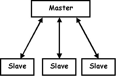
In computer networking, master/slave is a model for a communication protocol in which one device or process (known as the master) controls one or more other devices or processes (known as slaves). Once the master/slave relationship is established, the direction of control is always from the master to the slave(s). The County of Los Angeles, saying the term master/slave may be offensive to some of its residents, has asked equipment manufacturers not to use the term. Some manufacturers prefer the term primary/secondary.
These are the main network method
What will i do?
boards
- Node 1 : Attiny 45
- Node 2 : RGB LED
- Node 3 : RGB LED (Replicated)
This board i used in input week can be used as general purpose and here node 1 since i have pinout to 2 datapins and also FTDI header inorder transmit serial data
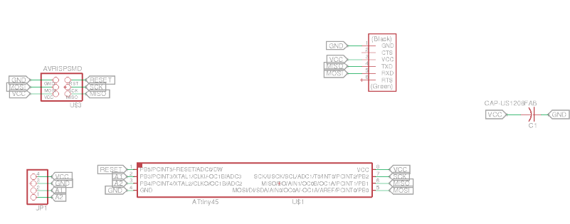
Here i am using RGB led which i made in output week other than my servo controlling board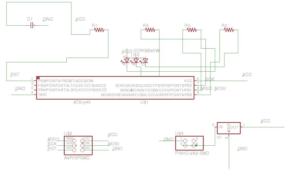
Replicated the same board i had
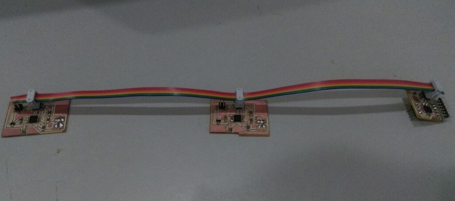
Nodes
Node 1 is fabricated in my input week for moisture sensor and node 2 and 3 are RGB Led amoung one is fabricated in output week other than servo.
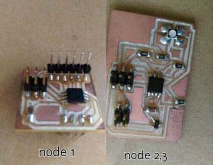
Connected with 3 node bus as shown
code in action
I used the below code inorder to test serial connection, once this i can proceed with the next step.The below code is used for test my master, the same way tested slaves.
             #include

   #include

   #define RxD 1

   #define TxD 0

   #define DEBUG_ENABLED  1

   SoftwareSerial blueToothSerial(RxD,TxD);

   int state = 0;


   void setup() {

     blueToothSerial.write("hiii");


     blueToothSerial.begin(9600);

   }

   void loop()


   {


   if(blueToothSerial.available() )

   {

     blueToothSerial.write("hii2");

    state = blueToothSerial.read();

    blueToothSerial.write(state);


    }


   }
In serial monitor sometimes i was able to retieve data correctly but with 90%
Master is working fine, in case of slave the result is showing inconsistant for me
TRY-2
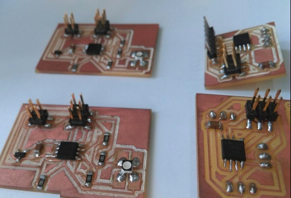
Then i switched to try with niels code with modifications and that "WORKED" well.I used below given 4 boards since my board dont have LED and planned to make use of RGB,what i did was made my two node as base in which it will power the RGB.
Code
Code for NODE 1
Code for NODE 2
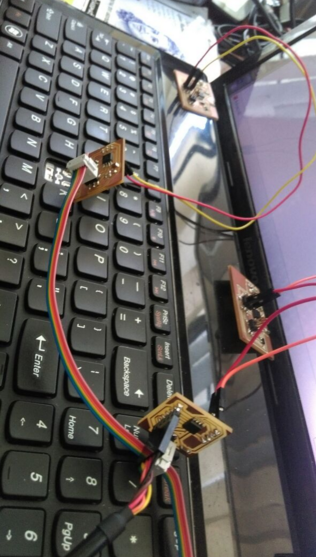
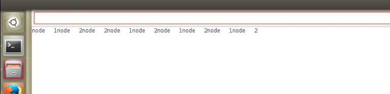
Response from the board
I used arduino IDE inorder to have Serial monitor, Burned my nodes and then opened arduino IDE's Serial monitor where i command to the slaves,when i press one .the node one will be blinked twice and when i pressed 2 the Node 2 will blink twice by the time in the screenshot of the above serial monitor can see the response, The below video express the succesful networking process.