1. Puneeth Raj
2. Kavita Arora
3. Muhammed Safwan
4. Nadeem Ahmed
5. Sarath S. M
6. Vishnu Easwaran E.
7. Yadu Sharon M. G.
The goal of this document is to outline information pertaining to Team 2 Group Effort for Fab Academy Machine Design Assignment.
Since there were 14 of us at the Fab Lab Kerala (in Trivandrum), our remote instructor Francisco divided us into two groups who would be working on two different machine projects. Puneeth was appointed leader for Team 2 for which this report has been documented. Francisco further added the following optional rules to make things interesting.
In our initial Team 2 Brainstorming sessions, we all looked at various ways we could converge over a project. The following areas were identified to think about:
1. Previous Fab Academy projects.
2. Interesting project suggestions and skills round-up of each team member:
3. We discussed amongst each other about the projects each of us had worked on, to get an idea about what each person had done before and if they could implement parts of it into the machine.
4. Needs of fablab: What are the things that fablab needs and if machine can be employed to do that.
5. With overview of machine in fablab.
6. YouTube videos - inspiring and interesting project videos in youtube.
After getting a good idea about what each of us is capable of, Puneeth lead us through an exercise for generating ideas. We were asked to generate as many ideas as possible in 5 mins. The nature of the ideas could be abstract, it could include, feelings, phrases, ways of fabricating, name of machine, anything that comes to our mind unfiltered and without judgement. A bunch of great ideas popped up because of this. This way of idea generation leads to most interesting of ideas and involves creative thinking. Random Brainstorming wouldn’t have been able to achieve this result as it involves a lot deliberation and multiple iterations.
We came up with a couple of interesting ideas:
* Telescope focusing bot.
* Cake decorating-bot or Chocolate 3d printer.
* Component selecting bot for electronics lab.
* Scanning bot.
* Mehndi drawing bot (Mehndi is Indian herbal paste that stains the skin brown temporarily thereby giving the effect of a temporary tattoo of sorts)
* Random sketching Bot.
* Time writing clock.
* Cloth cutting machine - that cuts cloths for tailors, when they feed the plans.
We shortlisted the following as the most feasible projects to discuss further, while adding more ideas that popped up:
* Time writing-bot: Too simple; Materials were easily available and could be fabricated in no time
* Wall climbing-bot: Too Difficult. Needed a lot of work and some major innovations would have to created from scratch with respective to the climbing/suction of the climbing bot.
* Component selecting bot: Doable project, with integration of linear stages and a novel design of the required end effector
* Laser Cutter: Not very doable, since we needed to source a laser powerful enough to at least cut through cardboard, which wasn’t possible unless we bought such a laser source
* Dosa Maker (dosa is Indian rice pan cake): Too complex a problem to start with, since it involved heating, rotation and many other complex procedures which are nice to do over a month combined with a lot of research and prototyping
* Chocolate printer
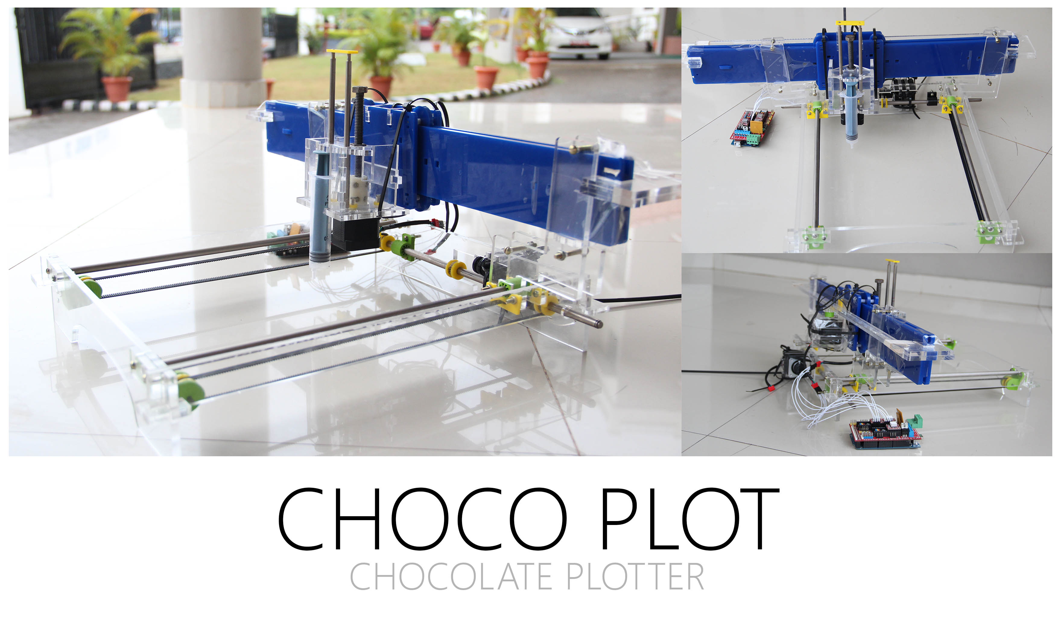
We unanimously decided that we would build our own custom Chocolate Printer - which would fulfill the criteria of a non-boring machine design, as well as ensure that we could use only parts and components that we could either make from scratch or salvage directly from old machinery lying around.
We did not have any mechanical components for fabricating Nadya’s cardboard linear stage directly. We did not possess, linear bearings, threaded rod, nylon bushes and motor-shaft couplings.
Responsibilities:
Puneeth Took the lead on creating the linear stages and making sure everything was going according to plan,
Kavita Since Kavita was new to machine design, she primarily decided to assist with any and all documentation efforts including liaising with all team members
Nadeem was in charge of assembly, he worked on salvaging and sourcing materials needed for the project, created and styled the team website, and also played a major role withing the end effector design team.
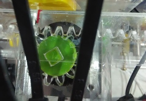
Yadu was put in charge of designing and assembling the End Effector for the machine design assignment
Safwan was working on conceptualising the machine and end effector
Sarath was designated as the initial Customer for the machine design assignment
Vishnu helped with the software programming aspects of the machine design assignment
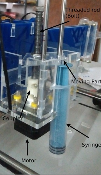
Sticking to the Francisco s Rules, Puneeth being the mechanical engineer in our team began designing his own version of fab-able linear stage.
Puneeth created a cardboard prototype of the linear stage which was in his mind. The documentation can be found here
pslide
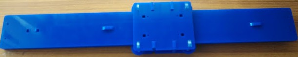
He began to work on creating the final linear stage with acrylic.
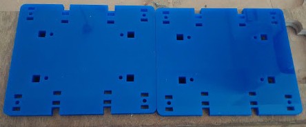
The acrylic rails were done and Puneeth started working on the mounting plate
Some of us had a discussion again about the project and we felt a chocolate writer would be
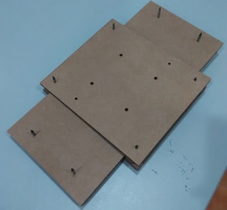
The mounting plates were cut.
After many tests, we created a press-fit comb to figure out the ideal slot thickness, A snapping tooth feature of the snap-fit mechanism was arrived at, and the spacers for the mounting plates were cut.
Coming together of all our bits and pieces of notes and documentation and formatting it in form of a presentable webpage.
Looked for possible options for controllers that can be fabricated in house. We were still waiting for the gestalt stepper nodes to arrive. Puneeth continued with his efforts on the linear slide. The spacers needed some more modification to make more space for parts of things like screw or snapfit clamps to fasten motor or end effector would be accommodated better between the mount plate and the rail.
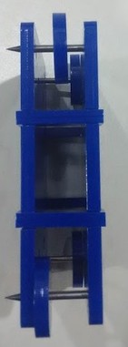
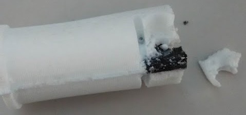
Also designed clamps to cover the pointy edge of the shaft(broken roland bit) so that it doesnt hurt anyone while handling.
The fully assembled linear stage.
The motions were not as smooth as we wanted it to be. We added two sheets of paper in between the top most layer and the middle and the it was smoother but still used to get stuck at certain places. It was due to the conical beam resulting in bevel cut that was causing the problem. If the wheel and the middle acrylic sheet were positioned such that the bevel of the wheel complements te bevel in the sheet cutting it could improve the performance, and thats what happened. The slide showed better movement when the the mechanisms are compensated for the bevel.
The angle of laser cutting from the wheel canceled the angle of the cut from the slide.
The movement improved a lot but this system could not be deemed perfect.
We were looking at various option for transmission and positioning. We had salvaged timing belts from the printer. These were very thin and and we were skeptical about the loads it could take, but we didnt have much load to be transferred. We didnt have that smooth a linear slide and the we had to design the pulleys for the belt too. The tooth of the timing belt was very small which would make it prone to slipping.
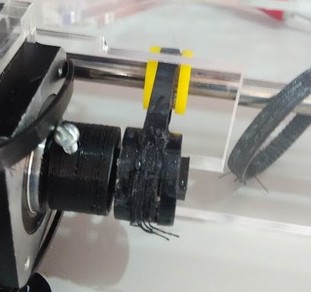
Puneeth started working on a concept of motor mounting which doesnt use the m3 threads that are available in the motor to mount. Here in Trivandrum its hard to find metric fasteners.
A acrylic pressfit cage holding the motor and pressfit on a another acrylic plate that is mounted on the linear slide using the inch screws.
We used inch screws because the linear slides were already fabricated and there were no provision to attach this. The idea is that the friction in the preffit which is pressfit over a large surface area would be sufficient clamping force for the motor to stay put.
Motor clamp was cut.
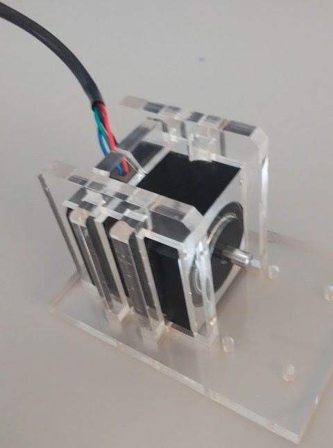
Although it was easy to fabricate, the acrylic shatters easily and in some direction it is very weak. The acrylic gave a tight fit but some of them shattered because we werent very careful in assembling them together. But we were still able to create the cage with broken yet functional pieces.
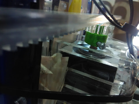
Puneeth designed a timing pulley that could be cut by laser. The problem was that the belt could easily slip the timing pulley. We have to think of another transmission system or get a better belt and pulley system. Experimenting on fabricating these could cost us more time, we were hinking of finally buying these stuff.
Figuring out what transmission to use. Couple of feasible options other than the belt - rack and pinion. Cable drive/capstan mechanism. We decided to work parallel for both mechanism. We needed to test driving mechanism for the linear stage, test and improve the main mechanical frame, test extrution, fix the belts on the mechanical frame and test the motions, figure out the kinematics of the machine, control the machine using cnc controller, send g code and confirm the motion.
The capstan mechanism would work similar to whats shown here https://www.youtube.com/watch?v=sXl1Ei3O2hA.
The use of double sided tape a good prototyping fastener to check the positioing, assembly and dimensions of a flat surfaces became very obvious and we used it extensively to put together stuff quickly.
Pulley - 3d printed problems faced- strength in direction- if printed legth direction alligning a direction- breaks easily. The design could be better in order to reduce the cantilever action. The Pulley could be placed in a way that aligns the layer favourable to force/ moment applied
From Now on we wont be posting day wise, instead th overall work done till the end.
Driving mechanism
Rack and pinion: We used http://hessmer.org/gears/InvoluteSpurGearBuilder.html to generate the rack and pinion. We tried to keep the teeth numbers more, tooth length less so that it is strong even if it is acrylic and the gear profile to be around the radius of 11mm so that we can place the rack and pinion assembly between the mount plate and the motor . For the pinion 3D printing was also a good option.
Problems
Bending of the rack- Can cause backlash and sliping and unreliable distance moves.
Solved by adding a piece of acrylic in between the rack and mounting plate. This piece(yellow in color in the pictures above) slides on the rack and keeps the rack and pinion engaged.
Backlash- There will be backlash always when using a simple rack and pinion attachment. You can load it in one direction with an elastic load or a weight.
I forgot the exact parameters I used to create the rack n pinion with so I have to use other methods to figure out the kinematics(steps per mm).
Capstan-
Extruder assembly
Linear sliding bushes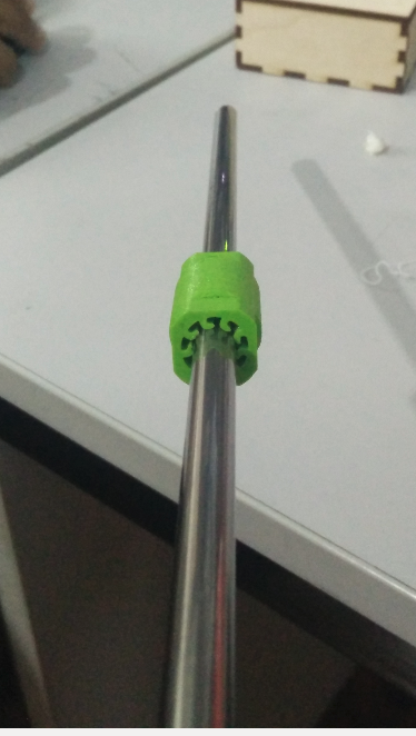
Final assembled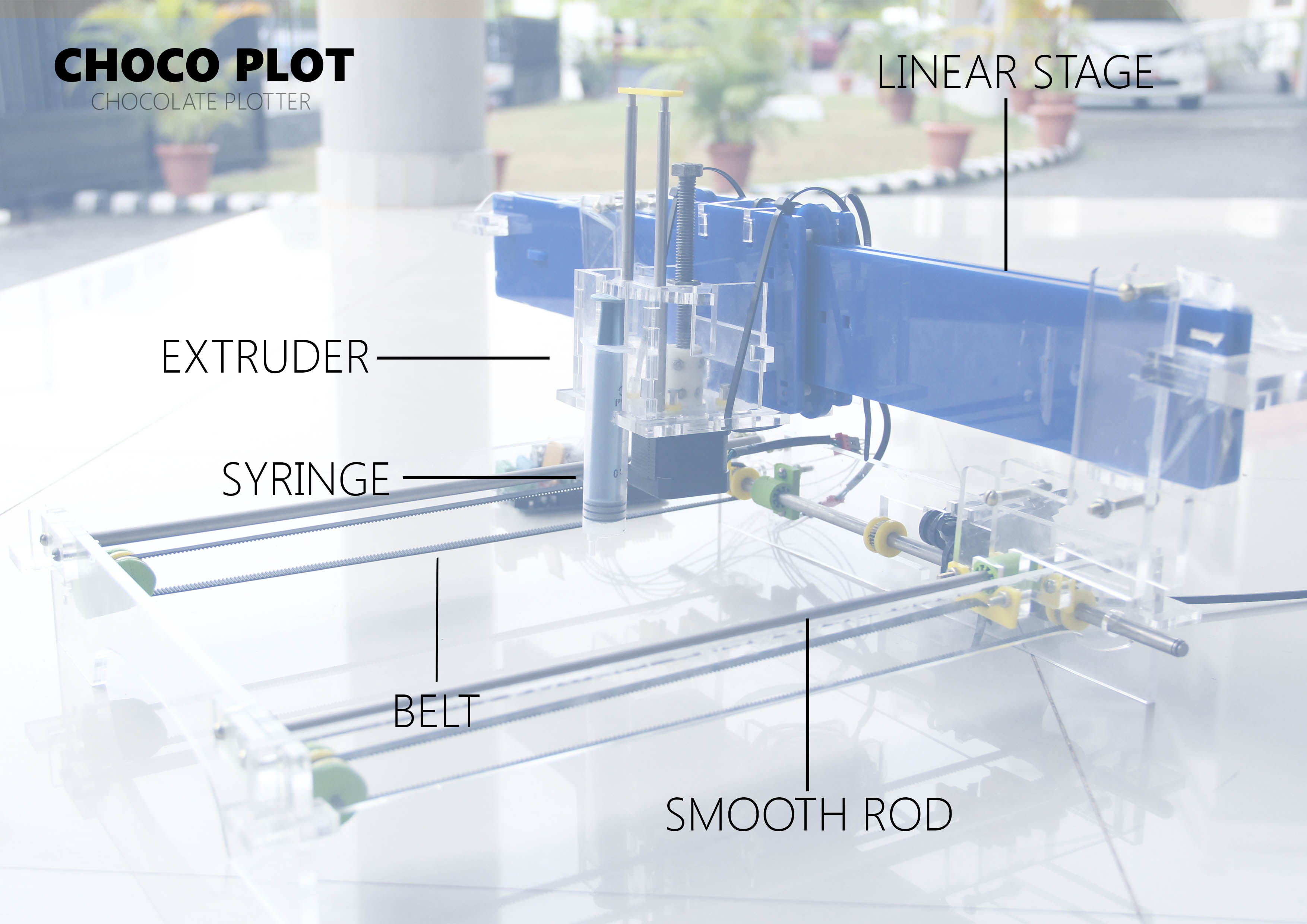
Problems and possible solutions
We used Arduino mega with RAMPS motor shield and Marlin firmware.
Pronterface was used as the gcode sending software.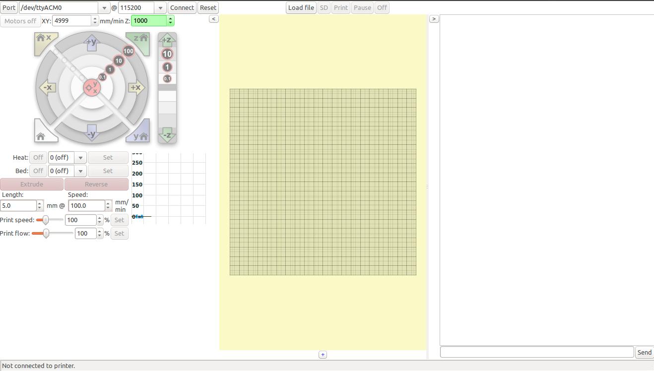
The following changes had to be made in the marlin firmware in order for it to work smoothly with our setup.
Config.h
Baudrate is 250000 by default, pronterface had problems with 250000
Disabling temperatre sensor.
Disabling limit switches, since currently we arent using them.
We wanted it to move in negative direction too, its convenient for testing purpose same is true for minimum position and max position.
SanityCheck.h
Commenting out the last condition was necessary, because it doesnt compile with temperature sesor 0 disabled and throws error at compilation.
The x steps per mm was found by running the pinion one full rotation and measuring the distance moved by the axis during this move and 3200 (steps for full rotation) by this distance gives steps per mm.
To measure the steps per mm of the extruder I set the extruder steps permm to as that of x axis and just extruded it while running the x axis as the multiples of moves of x axis, until I found a satisfactory thickness of the extrusion over the move, of course the distance of the nozzle from the work surface should also be maintained the same. This multiple will be multiplied by x steps per mm to arrve at the extruder steps per mm.
Steps per mm 32 is used initially because its convenient that for a move of 100 through g code or saftware the motor make one full rotation. The moves of 10mm 1mm or 100mm are stadard moves in the software inteface.
The axis moved 59 mm for full rotation. Steps per mm of x axis was found as 3200/59 = 54.2372. The extrution of twice the length of x move seemed to give good extrusion results hence the steps per mm of extruder was put as twice that of the measured stepss per mm of x axis. This was meant for testing only. We need to update this in slicing setting too.
Problems and possible solutions
You can find the design files of linear stage in Puneeth's page.
For chasis design and files of motor coupler you can head to Yadu's page