In short I am trying to create a version of this
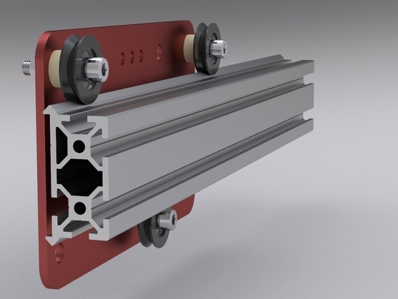
source: http://www.ulule.com/makerslide/
Here is the link to my group page.
Pslide My version of fabable linear stage.
I’ve had interest in making linear guides without using any high precision components, like linear bearings and precision blocks etc. I have found this design used in many cncs and always wanted to make one and use it. So I began thinking about a fabable version of it with low precision and low friction ability and most importantly be used for quick prototyping.
Upon iterating on many many ideas and I converged on a version of linear slide which can be fabricated using laser, acrylic and broken 1/8 th inch bit of modela and shopbot to act like pins and shafts.
Here is a very cool page which has lots of ideas for diy linear slides.
In short I am trying to create a version of this
source: http://www.ulule.com/makerslide/
Instead of groove in the wheel, which is hard to create I chose to make the groove y sandwiching 3 layers of acrylic to create a groove. And the wheel which is laser cut rolls inside the groove.
I made the initial design in draftsight. The clever part is that this works for any material of any thickness as long as it is laser cut and we use 1/8 inch shaft. If you want to use other shafts and different screws you have to change the diameter of few circles in the design.
Here is how the cardboard prototype looks like.
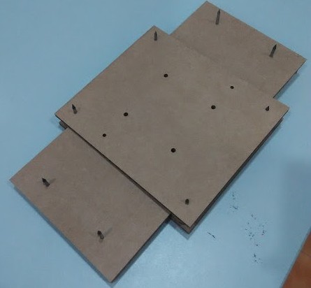
Side views.
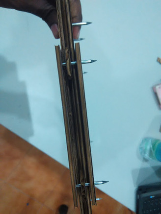

pslide
Further
Its not going to work straight away in acrylic. The plan is to adjust the wheels dia of on one side of the mechanism by fraction of an mm making it either smaller or bigger to adjust the friction and precision of motion in the mechanism. Too big and too tight would encourage a lot of friction, too small and too loose would make it wobble. In both cases the smooth motion can be adversely affected.
I realised that the dimensions of the plates could be reduced, and again forgot adding fillets to the drawing. Fillets make it nice on the hand when handling the material. This I will take into account while designing for acrylic.
More importantly I had to think of a way where in I can attach another axis without using nuts and bolts, A fastening mechanism which is pretty sturdy and rigid. My mind was deliberating on a modification of snap fit to make it more rigid and sturdy. I had to make designs and test it out before I integrate it into my design.
I also think its a good idea to add a counter balancing weight on the axis taking more load and going to be vertical.
Things to do
- Dimension a hole in acrylic proper for inserting 1/8 th shaft.
- Design a stopper for the shaft. The shafts are not of same length, the tool could break at different lengths.
- Design spacers to snap fit and maintain distance of acrylic plates.
- Design snapfit for attaching another stage on to the slide. Do it for one orientation now. Do this after deciding on or with the design of power transmission mechanism that is going to be used.
Update
- Design spacers for wheels. I realised that spacers are required to restrict relative motion between shaft and wheels along the length of the shaft. This would be 3d printed.
Execution
- I created an array of holes with dia ranging from 2.6 to 3.4 with 0.1 step to cut in laser, to check which hole fits best for the shafts we were using.
Download dxf
- Made a pressfit comb for 6m thickness.
Download dxf
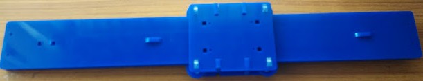
- Designed snapfits spacers for spacing the plates.
Download dxf
Problems faced
- Acrylic turned out to be too stiff for snap fit like product and laser doesn’t give a straight cut as the beam that is cutting is conical. This creates problem. 3D printing is a good option but we cant create sharp corners, which is something we can have a workaround for but it takes time for each iteration to be printed and tested.
- Acrylic sheets have variations of about 0.7 mm. My fabacademy mate Sibu offered a suggestion in this regard. His suggestion was to differentially space the top most layer using sheets of paper until smooth motion of decent fit is achieved. This requires me to use nuts and bolts to tighten or design a modular/discritised way to fasten plates together.
The development of the acrylic stage has been documented in the team page from day 4 to day 8.
Download slide cutting files, dxf
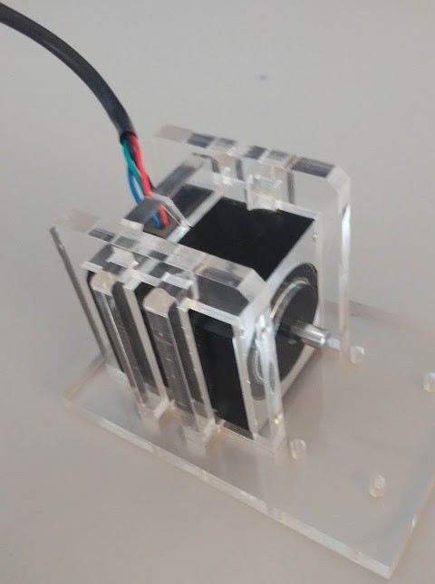
Through this design the motor can withstand forces in the plane but theoretically weak in handling the pulling forces way from the plane on which the motor is mounted. But if you can try get a good enough grip on motor varying the snapfit tightness.
Download motorclamp cutting files, dxf
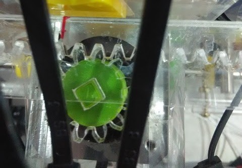
Download rack and pinion cutting files, dxf
I thought out different option for driving mechanism and decided to go ahead with rack and pinion. Here you’ll find my experiments in more detail.
Since we wanted to see the machine running as soon as possible before proceeding further, I used cellophane tapes and zipties to mount the motors whereevr possible. They turned out to be excellent quick prototyping options.
Conclusion
Acrylic is really brittle and shock prone, Many a times acrylic parts broke costing us time and patience.
While making pressfit mechanism it helps if we have rounded corners instead of sharp , to reduce stress concentration.
The x steps per mm was found by running the pinion one full rotation and measuring the distance moved by the axis during this move and 3200 (steps for full rotation) by this distance gives steps per mm.
To measure the steps per mm of the extruder I set the extruder steps permm to as that of x axis and just extruded it while running the x axis as the multiples of moves of x axis, until I found a satisfactory thickness of the extrusion over the move, of course the distance of the nozzle from the work surface should also be maintained the same. This multiple will be multiplied by x steps per mm to arrive at the extruder steps per mm.
Further Tweaking of the marlin firmware was taken up. All the edits made are documented here, You can also find details on caliberation runs there.
Conclusion
- 3.1mm dia circles laser cut and further drilled using 3.3 mm dia drill bits gave a good clearance and fit for the 1/8th shafts.
- 5.4 mm slots fit well.
- I’m gonna still use variations in designs on acrylic with laser cutting, testing and iterating gave 2mm thickness of acrylic over a length of 10mm flexible enough for snapfiting spacers.
Learnings
I had trouble getting to keep everyone in the same level of enthusiasm as me or as the maximum as possible. And instead of getting the group enthusiasm high my enthusiasm fell down, There were huge delays and I didnt know who was available at what time. To avoid these situation I shall pro actively interact with my teammates individually and understand their thoughts and their problem.