


W11 - INPUT DEVICES
Mission & initial concepts
Assignment
Measure something: add a sensor to a microcontroller board that you have designed and read it
Refererences to links i used
Files i used in this assignment
Electronic code
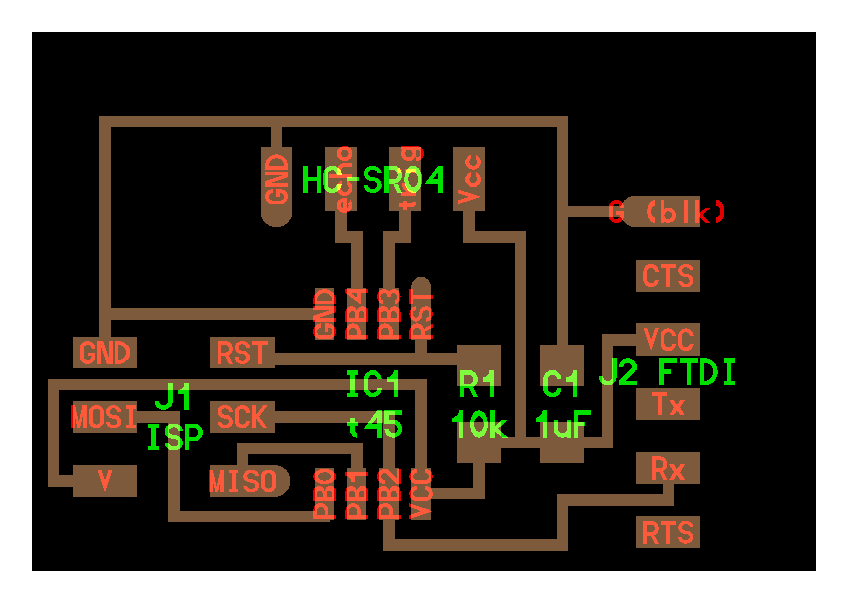
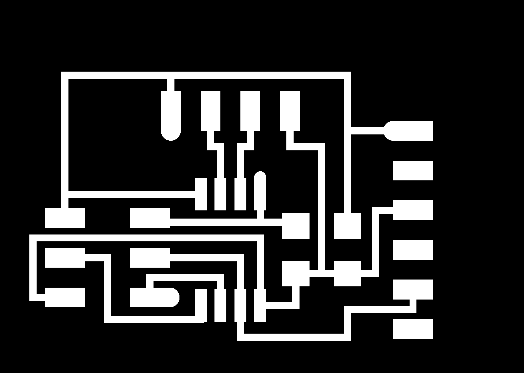
Planning of Pinouts (ppt)
Concepts and Inspiration
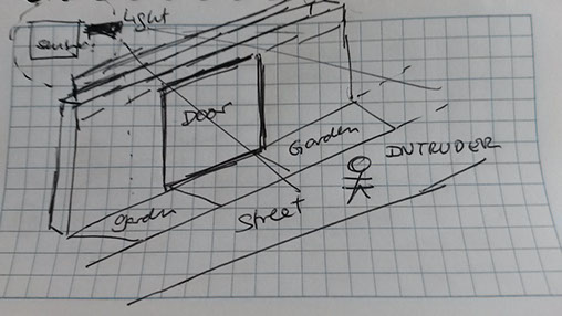
As documented before i liked the idea to have sensors that detect the presence of strangers in front of the house and react proactively.
Because of the zone (field) i would like to experiment with an ultrasound and variations to identify distances.
Technology
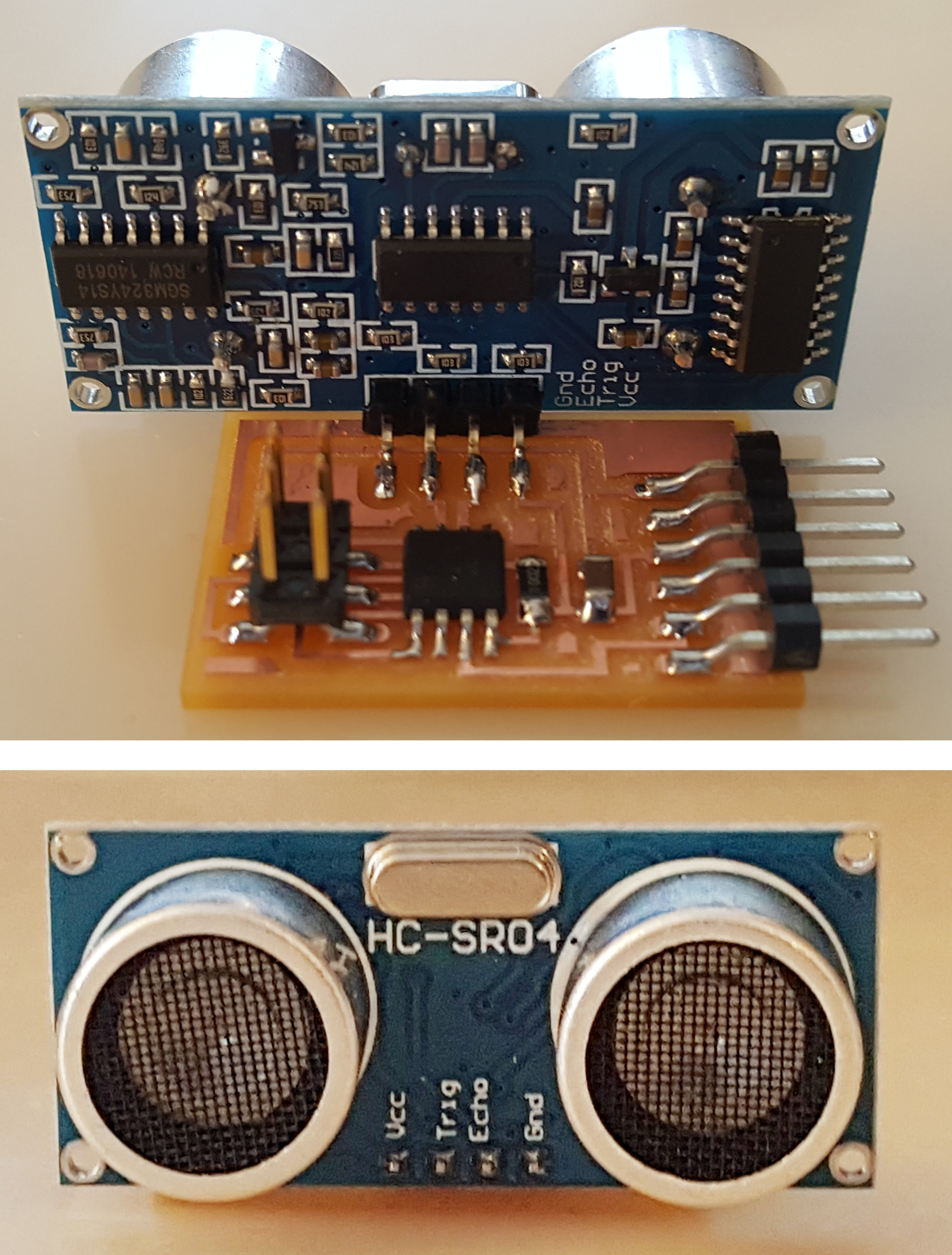
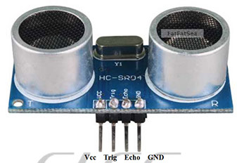
Ultrasonic Ranging Module
HC - SR04
http://www.micropik.com/PDF/HCSR04.pdf
Product features:
Ultrasonic ranging module HC - SR04
Provides 2cm - 400cm non-contact measurement function, the ranging accuracy can reach to 3mm.
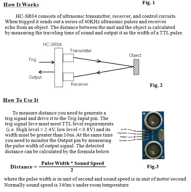
The modules includes ultrasonic transmitters, receiver and cont rol circuit. The basic principle of work:
- (1) Using IO trigger for at least 10us high level signal,
- (2) The Module automatically sends eight 40 kHz and detect whether there is a pulse signal back.
- (3) IF the signal back, through high level , time o f high output IO duration is the time from sending ultrasonic to returning.
Test distance = (high level time×velocity of sound (340M/S) / 2,
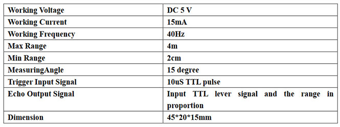
Electric parameter
Additional info i found interesting
Fabrication
I used the reference in order to generate the HC-SR04 driver
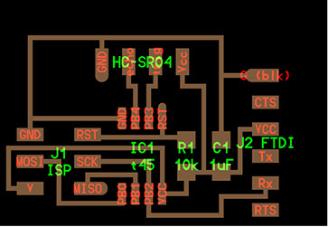
PROJECT=hello.HC-SR04
SOURCES=$(PROJECT).c
MMCU=attiny45
F_CPU = 8000000
CFLAGS=-mmcu=$(MMCU) -Wall -Os -DF_CPU=$(F_CPU)
$(PROJECT).hex: $(PROJECT).out
avr-objcopy -O ihex $(PROJECT).out $(PROJECT).c.hex;\
avr-size --mcu=$(MMCU) --format=avr $(PROJECT).out
$(PROJECT).out: $(SOURCES)
avr-gcc $(CFLAGS) -I./ -o $(PROJECT).out $(SOURCES)
program-bsd: $(PROJECT).hex
avrdude -p t45 -c bsd -U flash:w:$(PROJECT).c.hex
program-dasa: $(PROJECT).hex
avrdude -p t45 -P /dev/ttyUSB0 -c dasa -U flash:w:$(PROJECT).c.hex
program-avrisp2: $(PROJECT).hex
avrdude -p t45 -P usb -c avrisp2 -U flash:w:$(PROJECT).c.hex
program-usbtiny: $(PROJECT).hex
avrdude -p t45 -P usb -c usbtiny -U flash:w:$(PROJECT).c.hex
program-dragon: $(PROJECT).hex
avrdude -p t45 -P usb -c dragon_isp -U flash:w:$(PROJECT).c.hex
program-ice: $(PROJECT).hex
avrdude -p t45 -P usb -c atmelice_isp -U flash:w:$(PROJECT).c.hex
I used the .C file in order to program the board
#
# hello.HC-SR04.py
#
# HC-SR04 sonar hello-world
# hello.HC-SR04.py serial_port
#
# Neil Gershenfeld 11/15/15
# (c) Massachusetts Institute of Technology 2015
#
# This work may be reproduced, modified, distributed,
# performed, and displayed for any purpose. Copyright is
# retained and must be preserved. The work is provided
# as is; no warranty is provided, and users accept all
# liability.
#
from Tkinter import *
import serial
WINDOW = 600 # window size
filt = 0
eps = 0.1
def idle(parent,canvas):
global filt,eps
#
# idle routine
#
byte2 = 0
byte3 = 0
byte4 = 0
ser.flush()
while 1:
#
# find framing
#
byte1 = byte2
byte2 = byte3
byte3 = byte4
byte4 = ord(ser.read())
if ((byte1 == 1) & (byte2 == 2) & (byte3 == 3) & (byte4 == 4)):
break
low = ord(ser.read())
high = ord(ser.read())
value = (256*high + low)
filt = (1-eps)*filt+eps*value
us = filt/8.0 # 8 MHz counter
cm = us/58.0
x = int(.2*WINDOW + (.9-.2)*WINDOW*cm/50)
canvas.itemconfigure("text",text="%.0f cm"%cm)
canvas.coords('rect1',.2*WINDOW,.05*WINDOW,x,.2*WINDOW)
canvas.coords('rect2',x,.05*WINDOW,.9*WINDOW,.2*WINDOW)
canvas.update()
parent.after_idle(idle,parent,canvas)
#
# check command line arguments
#
if (len(sys.argv) != 2):
print "command line: hello.HC-SR04.py serial_port"
sys.exit()
port = sys.argv[1]
#
# open serial port
#
ser = serial.Serial(port,9600)
ser.setDTR()
#
# set up GUI
#
root = Tk()
root.title('hello.HC-SR04.py (q to exit)')
root.bind('q','exit')
canvas = Canvas(root, width=WINDOW, height=.25*WINDOW, background='white')
canvas.create_text(.1*WINDOW,.125*WINDOW,text=".33",font=("Helvetica", 24),tags="text",fill="#0000b0")
canvas.create_rectangle(.2*WINDOW,.05*WINDOW,.3*WINDOW,.2*WINDOW, tags='rect1', fill='#b00000')
canvas.create_rectangle(.3*WINDOW,.05*WINDOW,.9*WINDOW,.2*WINDOW, tags='rect2', fill='#0000b0')
canvas.pack()
#
# start idle loop
#
root.after(100,idle,root,canvas)
root.mainloop()
Also i needed to use this py (Python) file in order to manage from my computer
After compiling i just got a freezing window. In order to not be late with other assignments, i will continue, but i will use later this HC-SR04 in my personal project

Application on the HC-SR04 in my personal work
This component will be very useful for my project so i will try to use directly as part of my initial prototype of my project.
Because my skills in electronic are not so solid at this moment in order to facilitate the problem resolution process , i will execute the proof of concept in the following order:
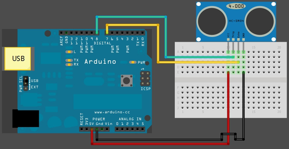
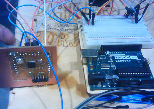
1. Make the connection with an Arduino UNO board
2. Make a simple prototype based on Arduino UNO (INPUT BASED)
3. Simplify the code and make a more complicate prototype (INPUT/OUTPUT BASED)
4. Create my own Fabuino
5. Move the already working prototype (defined in pint 3) on Arduino UNO to my Fabuino
6. Recreate the final prototype to Fabuino with additional parts
STEP 1: Make the connection with an Arduino UNO board
Programming code
/*
HC-SR04 Ping distance sensor:
VCC to arduino 5v
GND to arduino GND
Echo to Arduino pin 7
Trig to Arduino pin 8
*/
#define echoPin 7 // Echo Pin
#define trigPin 8 // Trigger Pin
#define LEDPin 13 // Onboard LED
int maximumRange = 200; // Maximum range needed
int minimumRange = 0; // Minimum range needed
long duration, distance; // Duration used to calculate distance
void setup() {
Serial.begin (9600);
pinMode(trigPin, OUTPUT);
pinMode(echoPin, INPUT);
pinMode(LEDPin, OUTPUT); // Use LED indicator (if required)
}
void loop() {
/* The following trigPin/echoPin cycle is used to determine the
distance of the nearest object by bouncing soundwaves off of it. */
digitalWrite(trigPin, LOW);
delayMicroseconds(2);
digitalWrite(trigPin, HIGH);
delayMicroseconds(10);
digitalWrite(trigPin, LOW);
duration = pulseIn(echoPin, HIGH);
//Calculate the distance (in cm) based on the speed of sound.
distance = duration/58.2;
if (distance >= maximumRange || distance <= minimumRange){
/* Send a negative number to computer and Turn LED ON
to indicate "out of range" */
Serial.println("-1");
digitalWrite(LEDPin, HIGH);
}
else {
/* Send the distance to the computer using Serial protocol, and
turn LED OFF to indicate successful reading. */
Serial.println(distance);
digitalWrite(LEDPin, LOW);
}
//Delay 50ms before next reading.
delay(50);
}
Video of Step 1 : Make the connection with an Arduino UNO board
STEP 2: Make a simple prototype based on Arduino UNO
I completely know that the first step was just copying and hoping to work, now i will create something more specific to my needs.
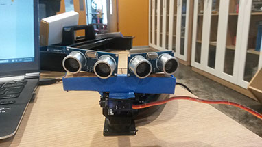
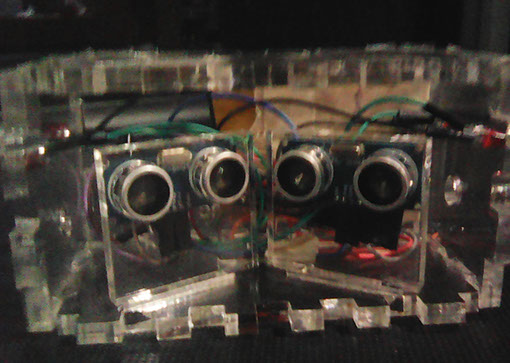
So i joint 2 SR04 with an angle of 120 degrees and with some carton and paper made an ugly box to support both of them. Also i use a support in order to include a servo motor and add algorith for following my hand.
Video of Step 1 : Make a simple prototype based on Arduino UNO
STEP 3: Simplify the code and make a more complicate prototype (INPUT/OUTPUT BASED)
#define trigPin1 8
#define echoPin1 7
#define led1 12
#define alarm 3
long duration, distance, UltraSensor;
float sinVal;
int toneVal;
void setup()
{
Serial.begin (9600);
pinMode(trigPin1, OUTPUT);
pinMode(echoPin1, INPUT);
pinMode(led1,OUTPUT);
pinMode(alarm,OUTPUT);
}
void loop() {
SonarSensor(trigPin1, echoPin1);
UltraSensor = distance;
Serial.println(UltraSensor);
if (UltraSensor < 10)
{
digitalWrite(led1, HIGH);
for (int x=0; x<180; x++) {
// convert degrees to radians then obtain sin value
sinVal = (sin(x*(3.1412/180)));
// generate a frequency from the sin value
toneVal = 2000+(int(sinVal*1000));
tone(alarm, toneVal);
}
delay(100);
}
else
{
digitalWrite(led1, LOW);
noTone(alarm);
}
}
void SonarSensor(int trigPin,int echoPin)
{
digitalWrite(trigPin, LOW);
delayMicroseconds(2);
digitalWrite(trigPin, HIGH);
delayMicroseconds(10);
digitalWrite(trigPin, LOW);
duration = pulseIn(echoPin, HIGH);
distance = (duration/2) / 29.1;
delay(100);
}
This prototype now include INPUT (Ultrasound sensor), OUTPUT (LED and PIEZO)
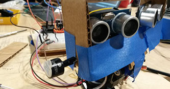
Notice the Leds on the front
Notice the piezo in the side
4. Create my own Fabuino
Please refer to Chapter of Electronic Design
5. Move the already working prototype (defined in point 3) on Arduino UNO to my Fabuino
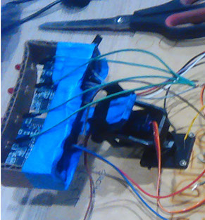
Now the challenge to move my already working prototype to my own Fabuino
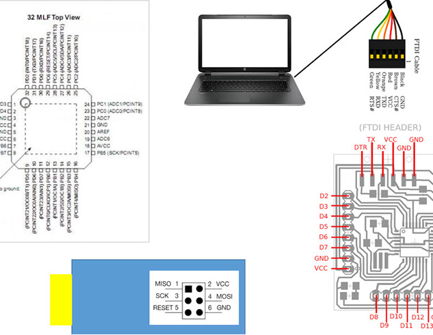
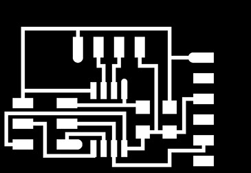
St first i planned in powerpoint how to use the new Fabuino and how to move the pinout
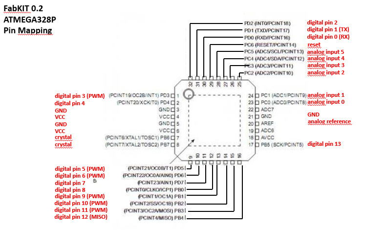
Also analyze the pinout differences and define the input and output components
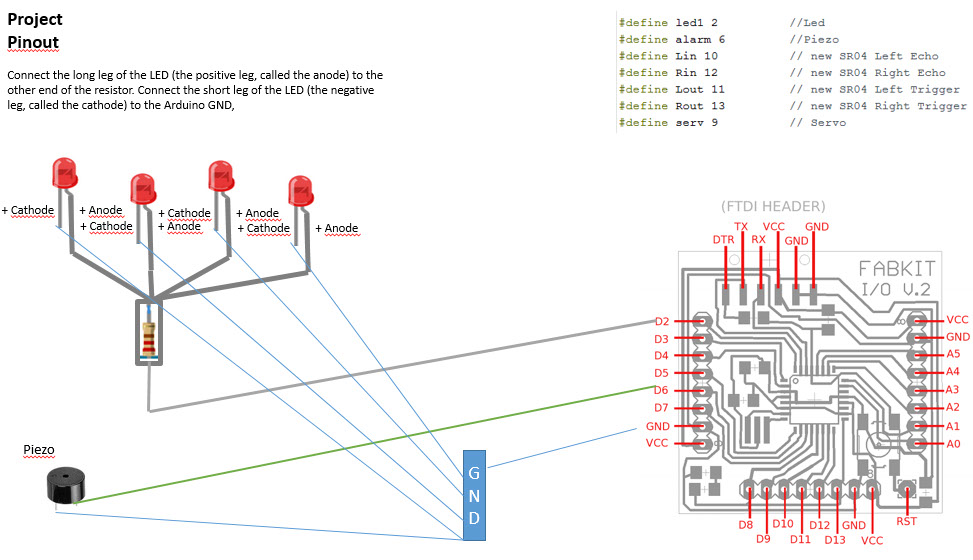
At last move the cables from one board to another
6. Recreate the final prototype to Fabuino with better looking parts
The design of it is in the mechanical section of the web page.
