


W3 - COMPUTER CONTROLLED CUTTING
Mission & initial concepts
Assignment checklist
COMPUTERCONTROLLED CUTTING
PART A: Design and make a corrugated cardboard pressfit construction kit
Learning outcomes:
- Demonstrate and describe 2D modelling processes
- Identify and explain processes involved in using the this machine
- Develop, evaluate and construct the final prototype
Have you:
- Explained how you drew your files
- Shown how you made your pressfit kit
- Eaten fresh vegetables today
- Included your design files and photos of your finished project
Files i used in this assignment:
INKSCAPE FILES
Scorpion
http://archive.fabacademy.org/archives/2016/fablabesan2016/students/70/projectfiles/w3/escorpion.svg
Sticker
PART B; Vinyl Cutting
There is no specific project that is focussed on this very useful tool. There are a range of ways you might utilise it throughout the programme, or your local instructor may set a specific project. You might make:
- stickers
- flexible circuit boards
- a textured surface/relief pattern
- screenprint resists/stencils
Ensure that you have used it in some way during this time and met the objectives below.
Learning outcomes:
Identify and explain processes involved in using this machine.
Design and create the final object
Have you:
Explained how you drew your files
Shown how you made your vinyl project
Included your design files and photos of your finished project
Lessons learned for previous class (10/02)
Blender is a good product to try for simulations
Focus in “how to” and no so in “what have I done”. I have big mistakes in assignment 2.
Try to document step by setp (like now)
Try to use the tools and document each one.
Based on some comments of Neil to other Fab Academy studentsFor my final project, I should be focus on the “sensor” right now and no so in the whole solution. My final user is at this moment the owner of the personal garage
Web pages and/or tools i should review
• Review 123D (www.123dapp.com) before Fusion
• Review fabmodules.org continuously
• Review and review again http://academy.cba.mit.edu/classes/computer_cutting/index.html
• Inkscape (tutorials)
• Visicut (tutorials)
Some concepts to review in order to properly understand:
• Halftones holes (impresión por huecos in Spanish)
• Press fit construction kit
• Type of joints
• parametric designs
• Flexures
CONCEPT 1: HALFTONES HOLES
I made some google searches looking for halfones and laser:
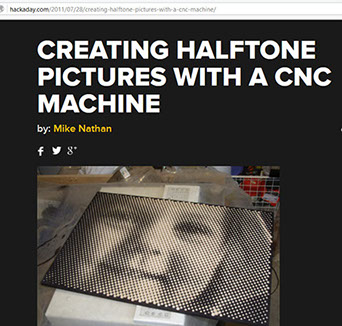
So I understand the idea of generating a content based on a number of not complete holes, very impressive.
Also I understand that I should work with an specific type of file : DXF
Let´s google it: DXF, ok get it on Wikipedia
“AutoCAD DXF (Drawing Interchange Format, or Drawing Exchange Format) is a CAD data file format developed by Autodesk[2] for enabling data interoperabilitybetween AutoCAD and other programs.”
CONCEPT 2: PRESS FIT CONSTRUCTION KIT
Next. I am searching for the word “press fit construction kit” and found very interesting materials:
http://fabacademy.org/archives/content/tutorials/04_Computer-Controlled_Cutting/Press-Fit_Construction_Tips.html
http://makezine.com/2010/01/14/letters-from-the-fab-academy-part-1/
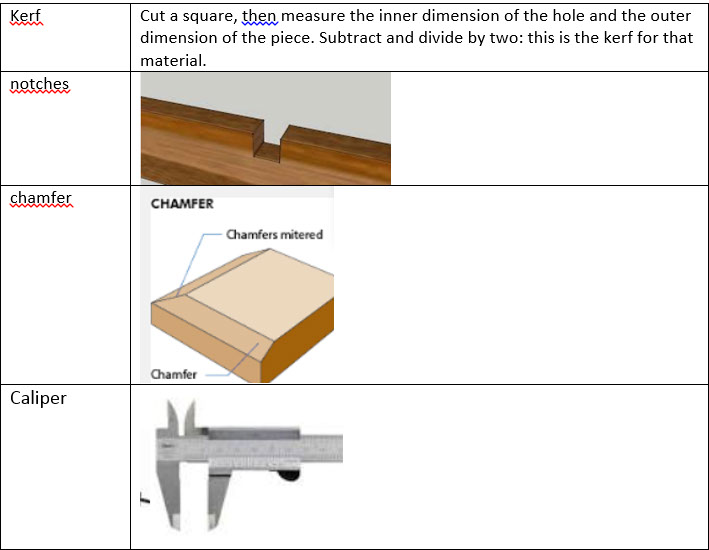
Now I understand that I do not understand some words, because of the language or because of the concept, so I decided to make my “translator” for each concept:
I like very much this extract:
http://makezine.com/2010/01/14/letters-from-the-fab-academy-part-1/
Full-featured CAD programs, like QCad, make it relatively easy to parameterize parts, but it’s also possible to use Inkscape to make parametric designs using the clone tool. First, follow these steps to determine the base size of a press-fit notch:
1. With calipers, measure the kerf created by your laser cutter. (You do have a laser cutter, don’t you?) Cut a square, then measure the inner dimension of the hole and the outer dimension of the piece. Subtract and divide by two: this is the kerf for that material.
2. Measure the thickness of the material, preferably with calipers.
3. Use these measurements to draw your best guess for a notch
4. Duplicate the notch a few times and bracket in .001 inch increments (i.e., make some at w-.002″, w-.001″, w+.001″, w+.002″ etc.).
5. Cut and test the fit
Once you have a good dimension, create a template layer in Inkscape with your basic notch shapes. When adding a notch to your design, use the Edit->Clone option to create a linked copy of the notch. When faced with modifying your drawing for a new material width, update the dimensions of the notchopic in the template layer and watch those changes update throughout the document.
Also find a two great tutorials in a wiki of FabLab for this topic:
http://wiki.fablab.is/wiki/Inkscape_how_to_make_a_pressfit_design
http://wiki.fablab.is/wiki/Inkscape_how_to_make_name_sticker
I like this idea in a previous FabLab : Some kind of industrializing the testing of power and speed before making the design. Just understanding the material.
http://fab.cba.mit.edu/classes/863.12/people/lindy/week2/index.html
CONCEPT 3: TYPES OF JOINTS
I start review the types of joints http://academy.cba.mit.edu/classes/computer_cutting/joints.jpg
I also review the gik model of Neil, I noticed that he used the second type of joints.
Just for a minute I get into this page: http://www.ncbi.nlm.nih.gov/pubmed/23359687
Stick and slip into articular joints… very interesting but not for my assignment. So I continue my exploration
ASSIGNMENT A:
Design and make a corrugated cardboard pressfit construction kit
Create a fit press construction kit. I´ve been sharing my thoughts with my son Diego of 8 years old. I told him and show the concept of the construction kit. He liked it.
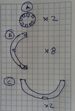
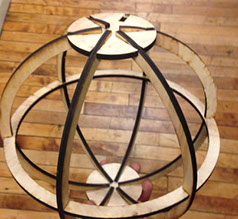
What could we do? He answer immediately. The Death Star of Star Wars and I liked it. So I search for some photographs on the Internet. We need ideas for creating an Sphere.
I liked this very much, because I could understand which parts are needed.
So my first challenge is how to create an Sphere, and search for ideas:
http://fab.cba.mit.edu/classes/863.14/people/sarah_jessop/week-01.html
It was inspired in a previous work at instructables.com
http://www.instructables.com/id/Press-fit-Construction-Kit/
So there are two types of joints in this project:
So I started my first design.
Then I found another version of Sphere more similar that I wanted
In my continuous research I found http://www.123dapp.com/make that allows anyone to create a press kit
So I installed 123dapp and search for an already created Death Star. I loaded it and show me following:
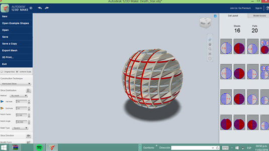
I switched Construction Technique from Interlocked Slices to Radial Slices and get a closer image to what I expected
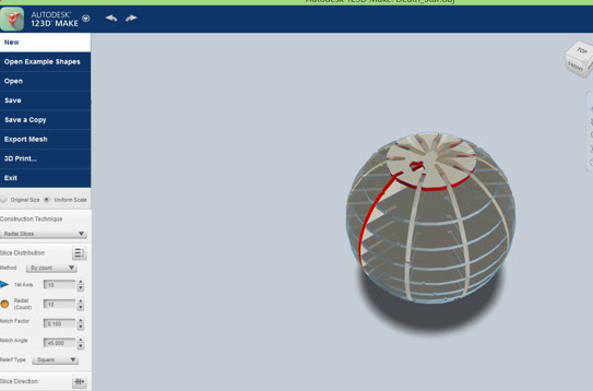
This is a great tool and also show me the slices I need internally. But it also show me that for a principant the Sphere was going to be very difficult.
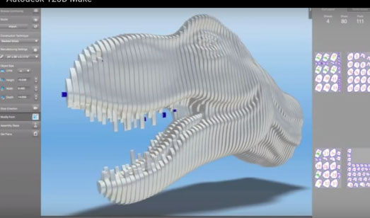
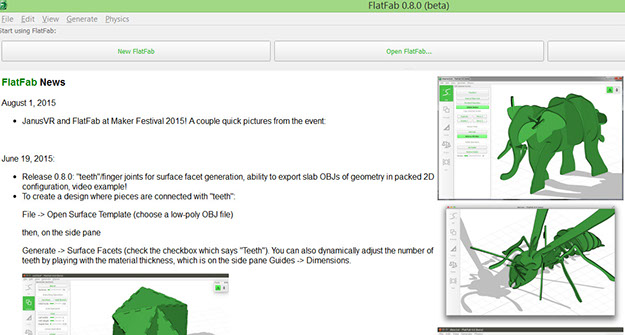
I continue making some research and found another great tool : Flatlab.com
It is in beta state but gave me some ideas to get 3D forms starting 2D forms
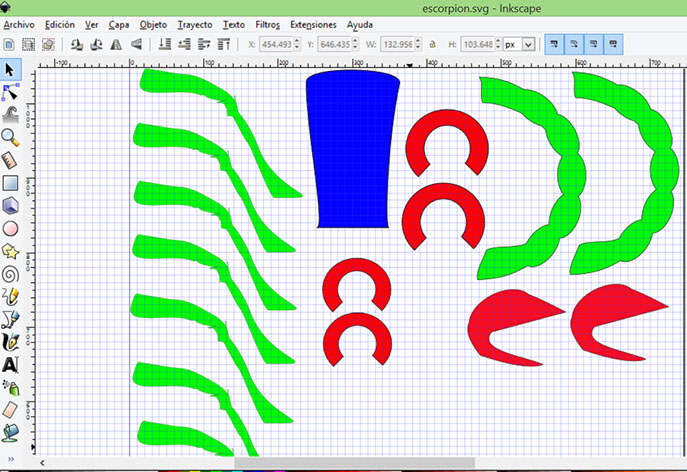
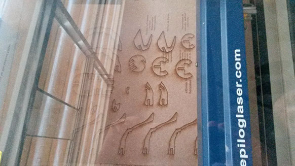
I decided that i was going to create an Scorpion. Just because someone found an Scorpion in the outdoors of the Fablab and now i some undertood how to create an insect or similar.

I used the ruler of I nkscape in order to find the dimensions and proportions of the Scorpion.
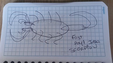
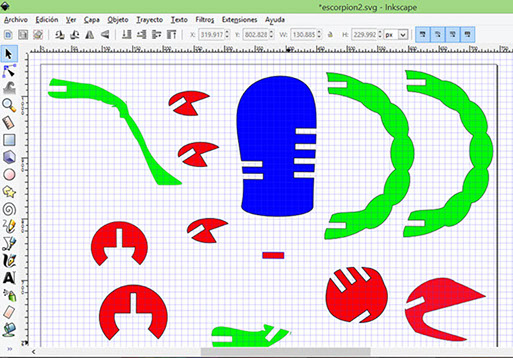
Scorpion v1 and Scorpion v2
I found Inkscape very usefull and easy to use. there are many tutorials on the internet. Drawing the parts and creating clones was not a problem.
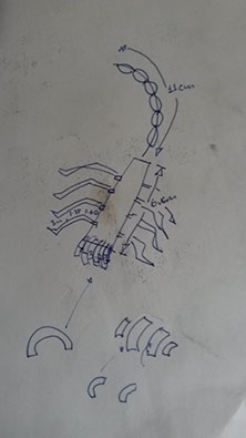
Understanding how to make the best notches was new for me. So i decided to make some tests based on my previous research. I was going to create an small square with diferent sizes, the calipe show me that the MDF has 3.11 mm width, so i was going to create +- options (0.1mm)
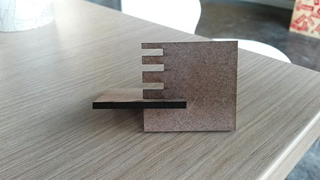
When i got the right size i included the squares in my design
Theni configure the lase cutter with following parameters
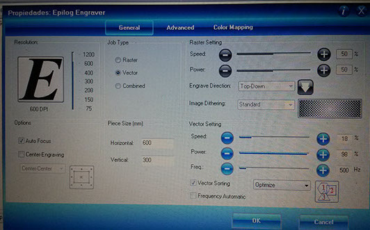
And it started to cut
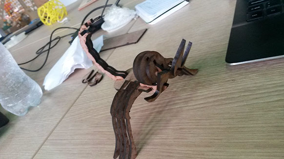
When finished i assembled it. It was done. =)
ASSIGNMENT B; Vinyl Cutting
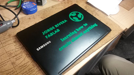
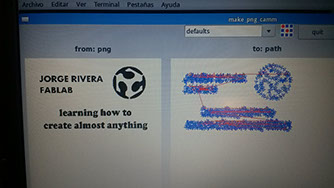
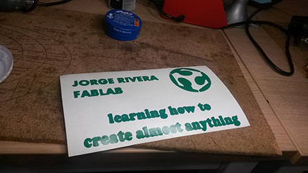
I decided to make an sticker for my laptop. So because of my previous work i decided to use again Inkscape

We need to setup the parameters at the cutter : force : 120, velocity : 2
When it was cutted, it was easy to get out the biggest unused parts.
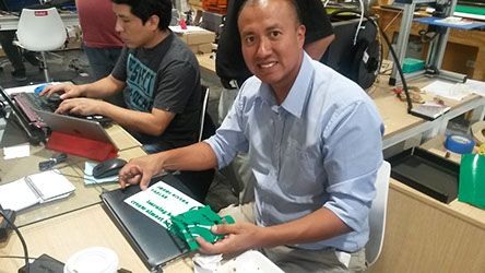
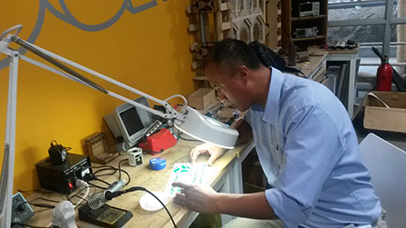
In order to get out the smallest unused parts i needed some glasses and more light.