


FINAL PROJECT
W00 - PROJECT DEVELOPMENT
Task:
complete your final project, tracking your progress:
what tasks have been completed, and what tasks remain?
what has worked? what hasn't?
what questions need to be resolved?
what will happen when?
what have you learned?
documentation during development
demand- vs supply-side time management
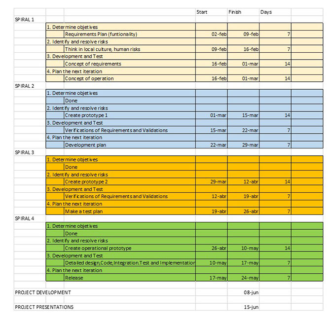
spiral development
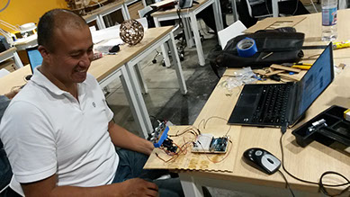
INTRODUCTION : THE FOLLOWER 1000 PROTOTYPE
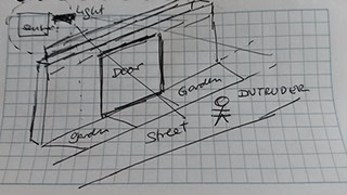
In the last month i bought a house in the field far away 20Kms (Pachacamac) from the city (Lima- Peru). It is not far away but because of the environment (forest) it does not have many services implemented.
So it has many potential areas for improving some specifics needs in that area like:
A) Security environment: There are some episodes of house intruders that could be prevented if proactive detected.
B) Light savements: Because of large spaces of each one houses, implemented some devices based on solar light could reduce light payment.
C) Decoration: It is a natural space so designing devices according to it will be a plus.
So my specific project will be focus in A) point. i think in some kind of mechanism that react based on external movement with light and also movement. (input sensors of movement and distance connected to a microcontroller that could react in output devices (motors and lights)
Having as optional improvements:
- Alert ONLINE to an external mobile phone with configured messages (IoT - Internet of Things approach)
- With a natural look (Molding approach)
Files i used in my personal project:
FILES
Electronic code
Case (box)
http://archive.fabacademy.org/archives/2016/fablabesan2016/students/70/projectfiles/caseplansv6.svg
Planning of Pinouts (ppt)
Standing
This component will be very useful for my project so i will try to use directly as part of my initial prototype of my project.
FABRICATION
Because my skills in electronic are not so solid at this moment in order to facilitate the problem resolution process , i will execute the proof of concept in the following order:
1. Make the connection with an Arduino UNO board
2. Make a simple prototype based on Arduino UNO (INPUT BASED)
3. Simplify the code and make a more complicate prototype (INPUT/OUTPUT BASED)
4. Create my own Fabuino
5. Move the already working prototype (defined in pint 3) on Arduino UNO to my Fabuino
6. Recreate the final prototype to Fabuino with additional parts
Project Management
I like the idea of spiral project management. Because of my background i used to work at the traditional project management style without thinking in recreating the prototype again and again to get better results. By the way, this is the 3rd version of my web page
Project Management Style and Activities
COMPONENTS
Input : 2 ultrasound sensors
Output : 2 piezos, 4 leds, 2 servo motors
Electronic : Fabuino connected with input/output dev
Programming : Arduino IDE
Prototyping Case : Wood cutted with laser
Prototyping Case final : Acrilic cutted with laser
ELECTRONIC DESIGN
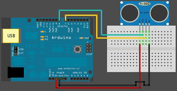
STEP 1: Make the connection with an Arduino UNO board
Programming code
/*
HC-SR04 Ping distance sensor:
VCC to arduino 5v
GND to arduino GND
Echo to Arduino pin 7
Trig to Arduino pin 8
*/
#define echoPin 7 // Echo Pin
#define trigPin 8 // Trigger Pin
#define LEDPin 13 // Onboard LED
int maximumRange = 200; // Maximum range needed
int minimumRange = 0; // Minimum range needed
long duration, distance; // Duration used to calculate distance
void setup() {
Serial.begin (9600);
pinMode(trigPin, OUTPUT);
pinMode(echoPin, INPUT);
pinMode(LEDPin, OUTPUT); // Use LED indicator (if required)
}
void loop() {
/* The following trigPin/echoPin cycle is used to determine the
distance of the nearest object by bouncing soundwaves off of it. */
digitalWrite(trigPin, LOW);
delayMicroseconds(2);
digitalWrite(trigPin, HIGH);
delayMicroseconds(10);
digitalWrite(trigPin, LOW);
duration = pulseIn(echoPin, HIGH);
//Calculate the distance (in cm) based on the speed of sound.
distance = duration/58.2;
if (distance >= maximumRange || distance <= minimumRange){
/* Send a negative number to computer and Turn LED ON
to indicate "out of range" */
Serial.println("-1");
digitalWrite(LEDPin, HIGH);
}
else {
/* Send the distance to the computer using Serial protocol, and
turn LED OFF to indicate successful reading. */
Serial.println(distance);
digitalWrite(LEDPin, LOW);
}
//Delay 50ms before next reading.
delay(50);
}
Video of Step 1 : Make the connection with an Arduino UNO board
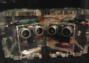
STEP 2: Make a simple prototype based on Arduino UNO
I completely know that the first step was just copying and hoping to work, now i will create something more specific to my needs.
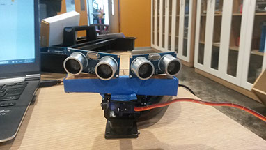
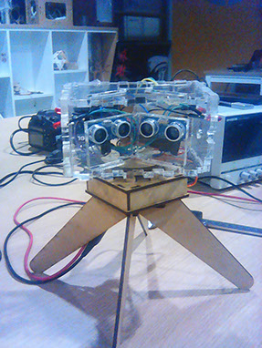
So i joint 2 SR04 with an angle of 120 degrees and with some carton and paper made an ugly box to support both of them. Also i use a support in order to include a servo motor and add algorith for following my hand.
Video of Step 1 : Make a simple prototype based on Arduino UNO
STEP 3: Simplify the code and make a more complicate prototype (INPUT/OUTPUT BASED)
#define trigPin1 8
#define echoPin1 7
#define led1 12
#define alarm 3
long duration, distance, UltraSensor;
float sinVal;
int toneVal;
void setup()
{
Serial.begin (9600);
pinMode(trigPin1, OUTPUT);
pinMode(echoPin1, INPUT);
pinMode(led1,OUTPUT);
pinMode(alarm,OUTPUT);
}
void loop() {
SonarSensor(trigPin1, echoPin1);
UltraSensor = distance;
Serial.println(UltraSensor);
if (UltraSensor < 10)
{
digitalWrite(led1, HIGH);
for (int x=0; x<180; x++) {
// convert degrees to radians then obtain sin value
sinVal = (sin(x*(3.1412/180)));
// generate a frequency from the sin value
toneVal = 2000+(int(sinVal*1000));
tone(alarm, toneVal);
}
delay(100);
}
else
{
digitalWrite(led1, LOW);
noTone(alarm);
}
}
void SonarSensor(int trigPin,int echoPin)
{
digitalWrite(trigPin, LOW);
delayMicroseconds(2);
digitalWrite(trigPin, HIGH);
delayMicroseconds(10);
digitalWrite(trigPin, LOW);
duration = pulseIn(echoPin, HIGH);
distance = (duration/2) / 29.1;
delay(100);
}
This prototype now include INPUT (Ultrasound sensor), OUTPUT (LED and PIEZO)
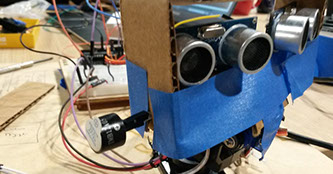
Notice the Leds on the front
Notice the piezo in the side
4. Create my own Fabuino
Please refer to Chapter of Electronic Design
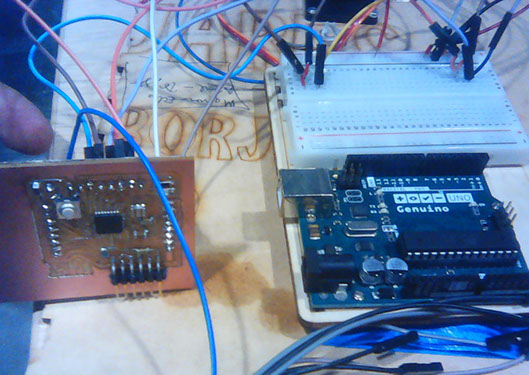
5. Move the already working prototype (defined in point 3) on Arduino UNO to my Fabuino
Now the challenge to move my already working prototype to my own Fabuino
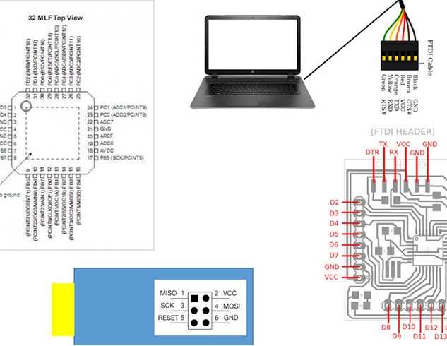
St first i planned in powerpoint how to use the new Fabuino and how to move the pinout
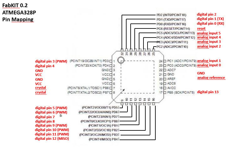
Also analyze the pinout differences and define the input and output components
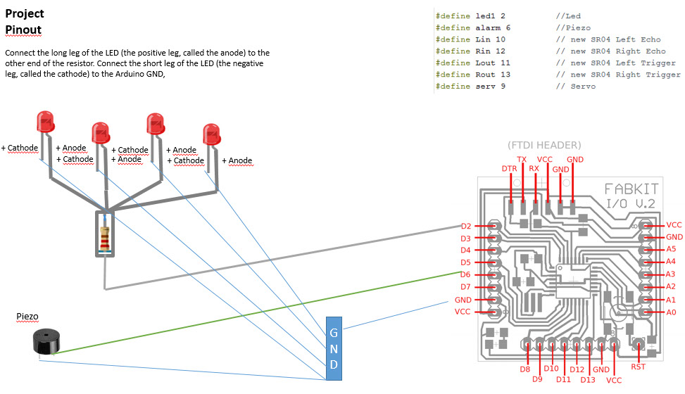
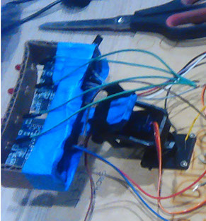
At last move the cables from one board to another
6. Recreate the final prototype to Fabuino with better looking parts
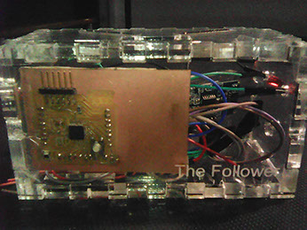
I finally generate a better box for including the electronic component, however it has a better look, it increment the weight of the whole prototype. This is an issue i should review in the next future.
Finally i uploaded the code that i generate for controlling the input and output devices
/*************************************************************************************************
**************************************************************************************************
Motion Follow
Created by Calvin Kielas-Jensen
Modified by Jorge Rivera@FabLab 2016
Using an Arduino UNO
- Leds (4)
- Ultrasound sensor (2)
- Piezo (1)
- Servo (2) - axis x and z
This script allows two ultrasonic range sensors to follow movement while mounted on the top of 2
servos in axis x and z. The distance threshold is 20 cm. To the origional of Calvin Kielas-Jensen, i have added
Leds,Piezo, 1 servo and planning to include an ESP8266 for communication with ThingsSpeak.
Anyone is welcome to use and modify this code as long as I am given credit. Thank you for
respecting the open source movement!
**************************************************************************************************
*************************************************************************************************/
#include <Servo.h>
Servo myservo;
// ** OLD const int Lin = 10, Rin = 12, Lout = 11, Rout = 13, serv = 9; //setting sensor pins and servo pin
// Define variables, pins
// establish variables for duration
// and the distance result in inches
// Define pins of sensors and actuors
#define trigPin1 8 //(old SR04)
#define echoPin1 7 //(old SR04)
#define led1 2 //Led
#define alarm 6 //Piezo
#define Lin 12 // new SR04 Left Echo
#define Rin 10 // new SR04 Right Echo
#define Lout 13 // new SR04 Left Trigger
#define Rout 11 // new SR04 Right Trigger
#define serv 9 // Servo
//Variables definition
long Rduration, Lduration, Rinches, Linches; //Use for SR04 new
long duration, distance, UltraSensor; //Use for SR04 old
int threshold = 15 ; //Sensor threshold in inches
int angle = 0; //Initial angle
int toneVal; //For alarm
float sinVal; //For alarm
boolean debug = true; //Serial communication for debuging. Set to true for serial communication.
void setup() {
// initialize serial communication:
if (debug)
{
Serial.begin(9600);
}
myservo.attach(9); //attach servo to pin 9
pinMode(trigPin1, OUTPUT);
pinMode(echoPin1, INPUT);
pinMode(led1, OUTPUT);
pinMode(alarm, OUTPUT);
}
void loop()
{
//Most of the sensor code has been taken from David Mellis's PING sensor code
//I modified it for a 4 pin sensor as oppsed to the 3 pin sensor
// Give a short LOW pulse beforehand to ensure a clean HIGH pulse:
pinMode(Rout, OUTPUT);
digitalWrite(Rout, LOW);
delayMicroseconds(2);
digitalWrite(Rout, HIGH);
delayMicroseconds(5);
digitalWrite(Rout, LOW);
Rduration = pulseIn(Rin, HIGH);
pinMode(Lout, OUTPUT);
digitalWrite(Lout, LOW);
delayMicroseconds(2);
digitalWrite(Lout, HIGH);
delayMicroseconds(5);
digitalWrite(Lout, LOW);
Lduration = pulseIn(Lin, HIGH);
// convert the time into a distance
Rinches = microsecondsToInches(Rduration);
Linches = microsecondsToInches(Lduration);
if (Rinches < 3 || Linches < 3)
{ digitalWrite(led1, HIGH);
for (int x = 0; x < 180; x++)
{
// convert degrees to radians then obtain sin value
sinVal = (sin(x * (3.1412 / 180)));
// generate a frequency from the sin value
toneVal = 2000 + (int(sinVal * 1000));
tone(alarm, toneVal);
}
delay(100);
}
else
{ digitalWrite(led1, LOW);
noTone(alarm);
}
if (debug)
{
Serial.print("Left: ");
Serial.print(Linches);
Serial.println(" in");
Serial.print("Right: ");
Serial.print(Rinches);
Serial.println(" in");
}
follow();
}
long microsecondsToInches(long microseconds)
{
// According to Parallax's datasheet for the PING))), there are
// 73.746 microseconds per inch (i.e. sound travels at 1130 feet per
// second). This gives the distance travelled by the ping, outbound
// and return, so we divide by 2 to get the distance of the obstacle.
// See: http://www.parallax.com/dl/docs/prod/acc/28015-PING-v1.3.pdf
return microseconds / 74 / 2;
}
void follow()
{
if (Linches <= threshold || Rinches <= threshold)
{
if (Linches + 2 < Rinches)
{
angle = angle - 2;
}
if (Rinches + 2 < Linches)
{
angle = angle + 2;
}
}
if (angle > 160)
{
angle = 160;
}
if (angle < 0)
{
angle = 0;
}
myservo.write(angle);
}
