


W7- COMPUTER CONTROLLED MACHINING
Mission & initial concepts
Assignment
- make something big
Link to Digital Joints
Link to Wall Curtain sample
Link to Frame/Panel definition
Files i used in this assignment:
Link to Inventor files SIDE
http://archive.fabacademy.org/archives/2016/fablabesan2016/students/70/projectfiles/w7/lado.dxf
http://archive.fabacademy.org/archives/2016/fablabesan2016/students/70/projectfiles/w7/ladov2.dxf
Link to Inventor files BASE
http://archive.fabacademy.org/archives/2016/fablabesan2016/students/70/projectfiles/w7/base.dxf
http://archive.fabacademy.org/archives/2016/fablabesan2016/students/70/projectfiles/w7/cara44.dxf
Link to Inventor files (Validation)
http://archive.fabacademy.org/archives/2016/fablabesan2016/students/70/projectfiles/w7/drilltest.sbp
Concepts and Inspiration
At this time of the year i am in the process of buying a new house for me and my kid. That will change dramatically my style of life but give us some personal benefits.
The house is in the field and it is made of non traditional elements. it has a lot of wood inside.
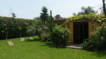
This is an old house with a lot of green areas... but, very dark inside because of the small windows.
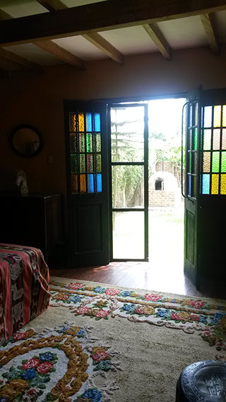
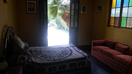
This was an opportunity for changing the doors and the walls. I like the idea of changing for something that is :
- modular
- based on wood
- available to include other components like glass for example
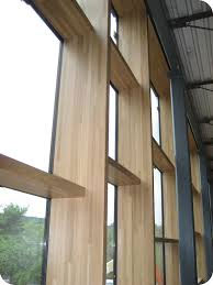
Curtain Wall (the concept)
A curtain wall system is an outer covering of a building in which the outer walls are non-structural, but merely keep the weather out and the occupants in. As the curtain wall is non-structural it can be made of a lightweight material, reducing construction costs. When glass is used as the curtain wall, a great advantage is that natural light can penetrate deeper within the building. The curtain wall façade does not carry any dead load weight from the building other than its own dead load weight. The wall transfers horizontal wind loads that are incident upon it to the main building structure through connections at floors or columns of the building. A curtain wall is designed to resist air and water infiltration, sway induced by wind and seismic forces acting on the building, and its own dead load weight forces.
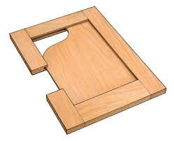
Frame and Panel
Frame and panel construction, also called rail and stile, is a woodworking technique often used in the making of doors, wainscoting, and other decorative features for cabinets, furniture, and homes. The basic idea is to capture a 'floating' panel within a sturdy frame, as opposed to techniques used in making a slab solid wood cabinet door or drawer front, the door is constructed of several solid wood pieces running in a vertical or horizontal direction [1] with exposed endgrains. Usually, the panel is not glued to the frame but is left to 'float' within it so that seasonal movement of the wood comprising the panel does not distort the frame.
Frame and panel construction at its most basic consists of five members: the panel and the four members which make up the frame. The vertical members of the frame are called stiles while the horizontal members are known as rails. A basic frame and panel item consists of a top rail, a bottom rail, two stiles, and a panel. This is a common method of constructing cabinet doors and these are often referred to as a five piece door.
Initial drafts and Designs
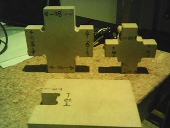
I tried many options as showed in the pictures. In my research i found also the "chidori system" concept that use low number of pieces (3) in order to create structures. So based on it i got my final ideas.
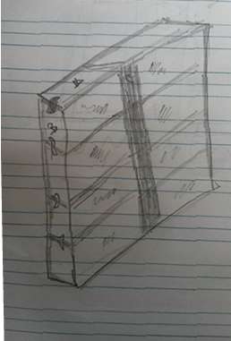
Finally i decided that i wanted to construct some modular mecanism of 2 or 3 type of components that allows me to construct curtain walls of wood with optional panels.
If success i will use it in order to remodel my future house.
Technology
Inkscape:
https://inkscape.org
Inkscape is an open-source vector graphics editor similar to Adobe Illustrator, Corel Draw, Freehand, or Xara X. What sets Inkscape apart is its use of Scalable Vector Graphics (SVG), an open XML-based W3C standard, as the native format.
Comment : Inkscape is a great tool to create the shapes using vectors. But there is a problem when you need exact measures. There is no good features to create in a fast and easy way. After some design, i decided to seach for another tool
Inventor (Autodesk
http://www.autodesk.com/products/inventor/overview
Autodesk Inventor, developed by U.S. based software company Autodesk, is a computer-aided design application for creating 3D digital prototypes used in the design, visualization and simulation of products. It uses ShapeManager, their proprietary geometric modeling kernel.
Autodesk Inventor competes directly with SolidWorks and Solid Edge.
At first Inventor was no easy to understand but our coach Gonzalo Siu give me some examples of practices and commands, based on that i start understand how to design in CAD approach and also parametric design
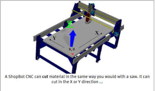
The Shopbot
http://www.shopbottools.com/mproducts/whatscnc.htm
A ShopBot is an amazing do-all tool for precisely cutting, carving, drilling or machining all kinds of things from all kinds of materials. With a ShopBot, you use the included software to design your parts on your personal computer, then, like a robot, the computer controls the cutter to precisely cut your parts. In the past, tools like ShopBots were strictly industrial tools and were referred to in factories as CNC (for Computer Numeric Control) tools. Now, the types of tools that create things by cutting material away or building up material in layers to create an object are called digital fabrication tools, and ShopBot's innovations have made them affordable for individuals and small shops.
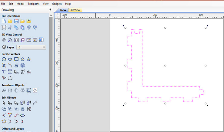
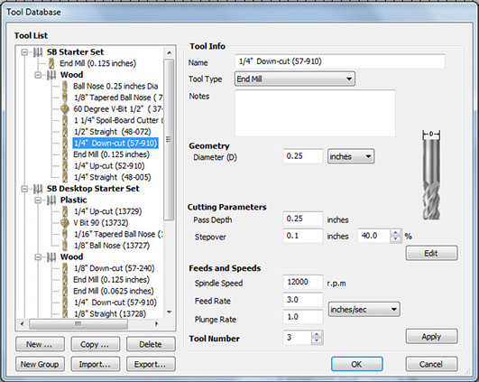
Vcarve
http://www.vectric.com/products/vcarve.htm
VCarve Pro and VCarve Desktop provide a powerful but intuitive software solution for cutting parts on a CNC Router. There are tools for 2D design and calculation of 2D and 2.5D toolpaths and along with the ability to import and toolpath a single 3D model (STL, OBJ etc.). There is also support to import multiple Vectric Clip Art 3D models (V3M) to create 3D assemblies.
The software can import 2D designs from other programs but also provides a full set of drawing and editing tools. The toolpath options cover all typical 2D routing operations such as Profiling, Pocketing, Auto-Inlays and Drilling as well as 2.5D strategies such as V-Carving, Prism carving, Fluting and even a decorative Texturing strategy. For 3D you can Rough and Finish the model and there are options to project 2D and 2.5D toolpaths onto the 3D surface. Each toolpath includes appropriate options to customize the settings and provide a high level of control for different types of operation. In addition all toolpaths can be previewed to show just how the part will look when it is actually cut, this allows instant feedback to allow toolpaths to be further optimized.
VCarve includes the functionality demanded for complex work while remaining incredibly easy to use and affordably priced. The software is used by cabinet makers, wood workers, sign makers, prop makers, plastic fabricators, hobbyists and in many other applications.
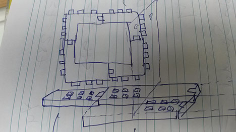
Planning
At first i had to design the master pieces of my multiuse window. My idea was to create the minimu number of parts in order to create a wall of wood. Here are my initial thoughts
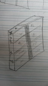
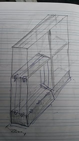
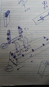
The draws show finally that in concept there should be only 2 parts in order to create a wall
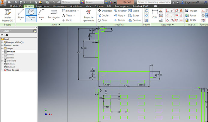
Designing
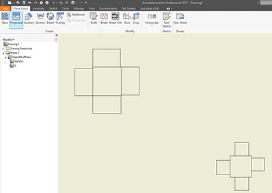
I used Inventor for designing the pieces. In order to create my design i needed two kind of pieces:
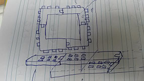
- The validation pieces : To validate the connection between the parts
- The connection pieces: SIDE and BASE
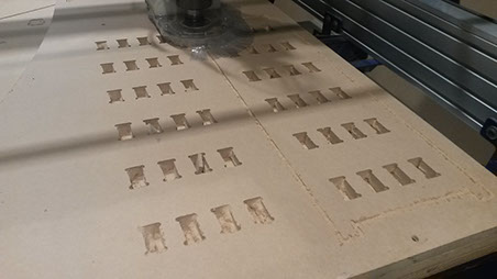
Notice that i created a tool with different sizes of holes so i could test which one get the best fit
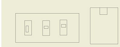
VALIDATION PIECES: These parts are for validation, so i can test the joints
CONNECTION PIECES: As told before for emsambling there are 2 types of pieces : BASE and SIDE
This is the base piece
This is the side piece
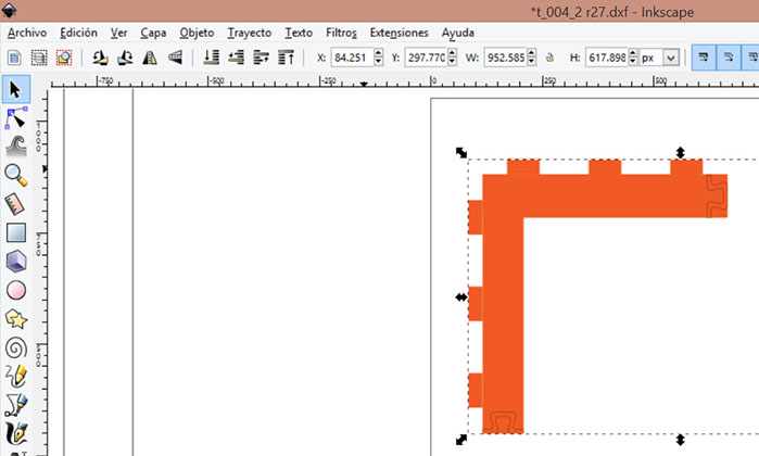
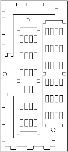
After the creation of the design pieces, i needed to import the files (DXF) into the software vCarve in order to be processed
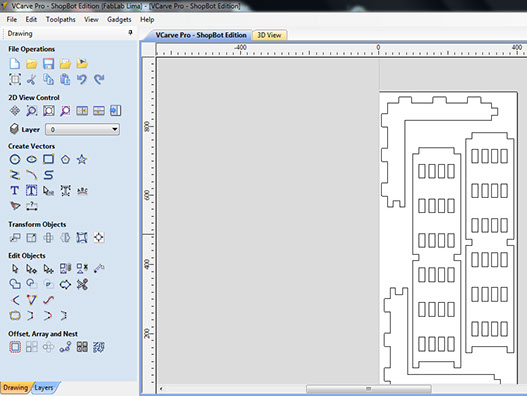
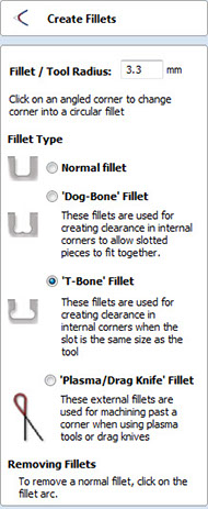
Also in order to have a good conectivity between the parts, i need to create filets as shown in the right graphic
In the vCarve tool based on the action it need to be done, i selected the options before executing.
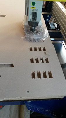
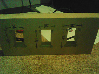
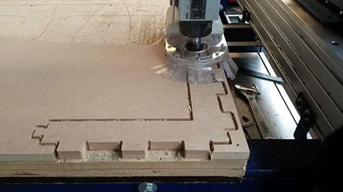
Process of creation of the CONNECTION PIECES after several tests with sample of VALIDATION PIECES in order to get the best joints that fits.
Finally i got the pieces for emsambling the final structure however when i tried to do it i realize that there was an additional need for supporting of the structure and because of the weight it does not support to be stable.
In order to not be late with the next assigntment i continue.
