


W8 - EMBEDDED PROGRAMMING
Mission & initial concepts
Assignment
- Read a microcontroller data sheet
- Program your board to do something, with as many different programming languages and programming environments as possible
- Extra credit: experiment with other architectures
Link to some resources i liked
FabKit (Fabuino) 0.2
http://fab.cba.mit.edu/content/projects/fabkit/
ATMega328P Info
http://www.digikey.com/product-detail/en/ATMEGA328P-AU/ATMEGA328P-AU-ND
ATMega328P Datasheet
Arduino UNO
Files i used in this assignment
(from Fab Academy):
Board
http://archive.fabacademy.org/archives/2016/fablabesan2016/students/70/projectfiles/w8/fabkit02.brd
Schematic
http://archive.fabacademy.org/archives/2016/fablabesan2016/students/70/projectfiles/w8/fabkit02.sch
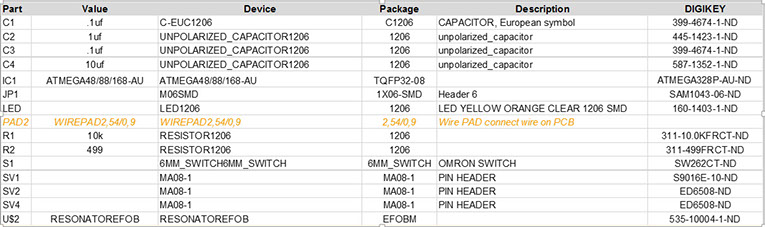
BOM
This is the relation of components, you can download from:
Programmed code
Starting the assignment
My mentor told me that Fabuino (or FabKit) is an open source option of Arduino, it uses processor ATMEGA328P and researching at this moment how to make a Fabkit will be the better way to understand a datasheet and aldo programm the processor.
Procedure
Because i will try to recreate a clone of Arduino i have to understand both processors, the one in the Arduino ONE and the one that is included as part of FabKit 0.2
So reviewing documentation the first info is that
FabKit 0.2 uses ATMEGA328P
Arduino uses ATMEGA328P.. the same! But it has a different look.
So back to the pinout section on the datasheet, i found following information:
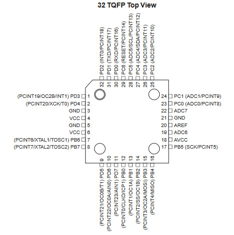
The image looks pretty much like the processor i receive in FabLab.
It has 32 pins, some are marked with
ACC o AVCC - Power
GND - Ground
And other options that i do not kwow at this time.
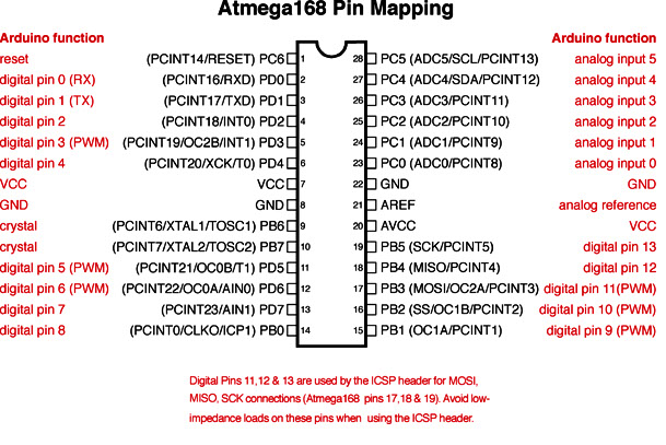
In the other hand i found the pinout of the Arduino UNO, so i understand that the same processors can have different presentations
Some processors share the same or similar structures, thats the reason why i am using the ATMEGA 168 instead of ATMEGA368P
Also there is some good additional information. It shows the relationship between the pinout and the functionality as an Arduino or Fabuino approach.
Best Practice
It is time to document my own version of this graphic. I really like it, it help me a lot to understand which PIN has which function and also allow me to have a better programming.
At this time i dont know the funtion of:
- ADC7
- ADC6
- AVCC
I will solve it later, for now it is better than good.

FabKit 0.2
Back to the fabkit and because my inttention is not just making it but programming some small action, like with Arduino.
Files
Here are the latest Eagle board and schematic files for 0.2 version. DO NOT use 0.3 and 0.4 versions, after some milling process my perception is that are not stable.
Board
http://fab.cba.mit.edu/content/projects/fabkit/fabkit02.brd
Schematic
http://fab.cba.mit.edu/content/projects/fabkit/fabkit02.sch
I prefer to use a tool in order to make the holes
The resonator
Is NOT optional. It is a must. Use the 8Mhz one
BOM
This is the relation of components, you can download from:
http://fabacademy.org/archives/2015/doc/projects/fabkit/fabkit-bom.xlsx
(yes i know, it is the version 0.3 or 0.4, but it works)
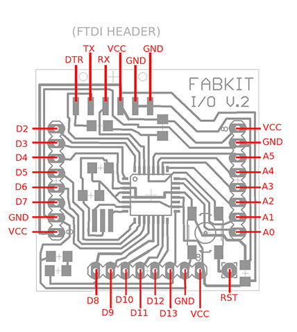
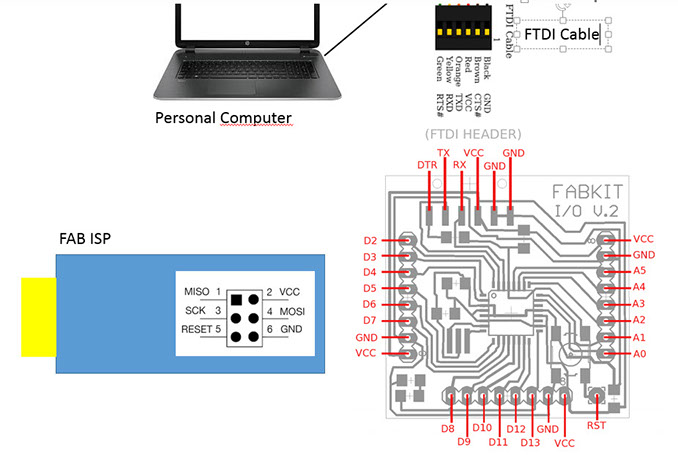
Connectivity
In order to have a a better understanding, i make my own diagram of connections and cables
Programming
In order to burn the bootloader. DO not use Windows, it does not recognize usb ports, instead of that, use Linux.
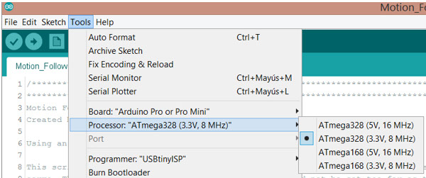
After you have burned it, you can manage via IDE in Windows. Because you are using the 8Mhzs resonator, use following options in IDE Arduino.
Tools - Board : Arduino Pro or Pro Mini
Tools Processor : ATMega328 (3.3,8Mhz)
Tools Port : Check the USB (not the serial) you are using
Programmer : USBTiny ISP
Then click : Tools - Burn Bootloader
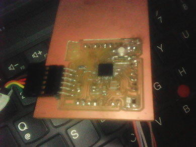
This is my final work, it takes me sometime but it is finished.
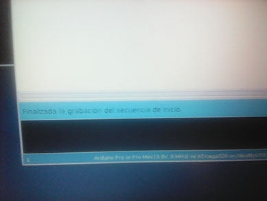
The message in spanish said that the sequence of start has finished.
(Burn bootloader)
Finally i uploaded the code that i generate for controlling the input and output devices
/*************************************************************************************************
**************************************************************************************************
Motion Follow
Created by Calvin Kielas-Jensen
Modified by Jorge Rivera@FabLab 2016
Using an Arduino UNO
- Leds (4)
- Ultrasound sensor (2)
- Piezo (1)
- Servo (2) - axis x and z
This script allows two ultrasonic range sensors to follow movement while mounted on the top of 2
servos in axis x and z. The distance threshold is 20 cm. To the origional of Calvin Kielas-Jensen, i have added
Leds,Piezo, 1 servo and planning to include an ESP8266 for communication with ThingsSpeak.
Anyone is welcome to use and modify this code as long as I am given credit. Thank you for
respecting the open source movement!
**************************************************************************************************
*************************************************************************************************/
#include <Servo.h>
Servo myservo;
// ** OLD const int Lin = 10, Rin = 12, Lout = 11, Rout = 13, serv = 9; //setting sensor pins and servo pin
// Define variables, pins
// establish variables for duration
// and the distance result in inches
// Define pins of sensors and actuors
#define trigPin1 8 //(old SR04)
#define echoPin1 7 //(old SR04)
#define led1 2 //Led
#define alarm 6 //Piezo
#define Lin 12 // new SR04 Left Echo
#define Rin 10 // new SR04 Right Echo
#define Lout 13 // new SR04 Left Trigger
#define Rout 11 // new SR04 Right Trigger
#define serv 9 // Servo
//Variables definition
long Rduration, Lduration, Rinches, Linches; //Use for SR04 new
long duration, distance, UltraSensor; //Use for SR04 old
int threshold = 15 ; //Sensor threshold in inches
int angle = 0; //Initial angle
int toneVal; //For alarm
float sinVal; //For alarm
boolean debug = true; //Serial communication for debuging. Set to true for serial communication.
void setup() {
// initialize serial communication:
if (debug)
{
Serial.begin(9600);
}
myservo.attach(9); //attach servo to pin 9
pinMode(trigPin1, OUTPUT);
pinMode(echoPin1, INPUT);
pinMode(led1, OUTPUT);
pinMode(alarm, OUTPUT);
}
void loop()
{
//Most of the sensor code has been taken from David Mellis's PING sensor code
//I modified it for a 4 pin sensor as oppsed to the 3 pin sensor
// Give a short LOW pulse beforehand to ensure a clean HIGH pulse:
pinMode(Rout, OUTPUT);
digitalWrite(Rout, LOW);
delayMicroseconds(2);
digitalWrite(Rout, HIGH);
delayMicroseconds(5);
digitalWrite(Rout, LOW);
Rduration = pulseIn(Rin, HIGH);
pinMode(Lout, OUTPUT);
digitalWrite(Lout, LOW);
delayMicroseconds(2);
digitalWrite(Lout, HIGH);
delayMicroseconds(5);
digitalWrite(Lout, LOW);
Lduration = pulseIn(Lin, HIGH);
// convert the time into a distance
Rinches = microsecondsToInches(Rduration);
Linches = microsecondsToInches(Lduration);
if (Rinches < 3 || Linches < 3)
{ digitalWrite(led1, HIGH);
for (int x = 0; x < 180; x++)
{
// convert degrees to radians then obtain sin value
sinVal = (sin(x * (3.1412 / 180)));
// generate a frequency from the sin value
toneVal = 2000 + (int(sinVal * 1000));
tone(alarm, toneVal);
}
delay(100);
}
else
{ digitalWrite(led1, LOW);
noTone(alarm);
}
if (debug)
{
Serial.print("Left: ");
Serial.print(Linches);
Serial.println(" in");
Serial.print("Right: ");
Serial.print(Rinches);
Serial.println(" in");
}
follow();
}
long microsecondsToInches(long microseconds)
{
// According to Parallax's datasheet for the PING))), there are
// 73.746 microseconds per inch (i.e. sound travels at 1130 feet per
// second). This gives the distance travelled by the ping, outbound
// and return, so we divide by 2 to get the distance of the obstacle.
// See: http://www.parallax.com/dl/docs/prod/acc/28015-PING-v1.3.pdf
return microseconds / 74 / 2;
}
void follow()
{
if (Linches <= threshold || Rinches <= threshold)
{
if (Linches + 2 < Rinches)
{
angle = angle - 2;
}
if (Rinches + 2 < Linches)
{
angle = angle + 2;
}
}
if (angle > 160)
{
angle = 160;
}
if (angle < 0)
{
angle = 0;
}
myservo.write(angle);
}
I use this video for showing how the code works. Inside the box is my fabkit.
