


W6 - ELECTRONIC DESIGN
Mission & initial concepts
Assignment
- Redraw the echo hello-world board,
- Add (at least) a button and LED (with current-limiting resistor)
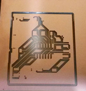
- Check the design rules, and make it
- Extra credit: simulate its operation
Useful Links:
http://academy.cba.mit.edu/classes/electronics_design/index.html
Learning Electronics
Import Eagle to io.circuits
http://blog.circuits.io/post/43564427971/take-your-eagle-designs-to-the-cloud
How to import libraries of Eagle into circuits.io
https://123d.circuits.io/eagle/import
Tutorial : Schematic con Eagle
https://www.youtube.com/watch?v=1AXwjZoyNno
Tutorial : We need a clock - Crystak or Resonator
https://www.sparkfun.com/tutorials/95
Files i used in this assignment:
Link to EAGLE schematic and board (v8)
Link to EAGLE schematic and board (v9)
Link to EAGLE preparation (ppt file)
Concepts and Best Practices Learned
I am completely new in electronics so i decided to started from the basics. Making some research i found following page:
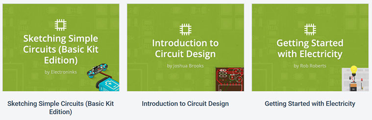
In these tutorials i learned following concepts:
- Voltage
- Current
- Resistance
- Ohm’s law
- Series vs parallel
- Basic circuit components & their function
- Basic circuit design
Eagle - The software of CADSOFT

EAGLE PCB Design Software is the tool of choice for thousands of engineers worldwide. With 3 modules and a common interface, EAGLE offers a variety of product combinations and allows every user to choose the configuration that meets their individual requirements.
You can download Eagle as Freeware with some limitations.
You can choose your software option. Here is a link of what you can find in the market
Eagle - The software of CADSOFT
123D Circuits.io enables beginners to easily get started with electronics. Instead of blowing up a component, you can now experiment freely in the live simulated virtual breadboard environment together with friends without being afraid of breaking something. 123D Circuits.io even allows you to simulate Arduino code along with your electronics to control it all or to learn about programming and Arduino. Let’s admit it, even pros could make good use of such a tool.
But don’t be fooled in thinking that 123D Circuits.io is just a toy. The underlying engine is still the powerful technology of circuits.io: easy to use circuit board layout tool, one-click PCB manufacturing service, live DRC, multi-layer boards, smart copper pours, large component library, Eagle import, auto 3D enclosure generation, modular design and much more!
We created a number of Instructables to help you get started with 123D Circuits.io and have extensive help pages, even including pointers to learn the basics of electronics.
Best of all is that 123D Circuits is still free for open designs, and affordable plans are available for those wanting more. I hope you are as excited as us about 123D Circuits.io. Head over to 123D.circuits.io and give it a try.
One of the best features you have in circuits.io is that you can simulate, but only if the components are available.
For Fablab it help me to understand but because of the origin of the components (Atmel not supported for simulation) i decided to switch to Eagle.
Circuits.io has a procedure to import libraries of Eagle into it, but without the simulation function
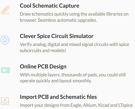
EASYEDA
EasyEDA is a free, zero-install, Web and Cloud-based EDA tool suite, integrating powerful schematic capture, mixed-mode circuit simulator and PCB layout in a seamless cross-platform browser environment, for electronic engineers, educators, students and hobbyists.
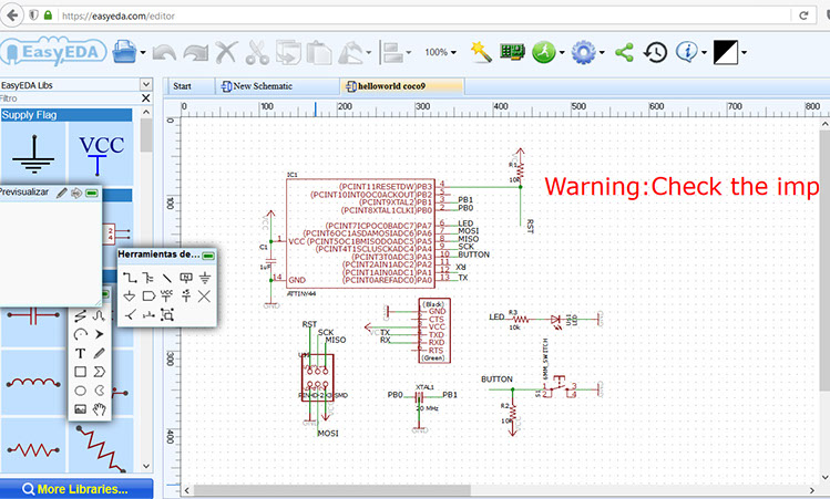
At this moment i am importing my already schematic (done in Eagle) into easyeda.com
I have some problems generating the PCB (design rules) i want to understand how to manage teh in EasyEDA.com
After the import i have receive a WARNING message that tells me that probably there are errors in my schematic.
Procedure
The first steps in order to proceed with the asigment was to understand some electronics basic concepts that i covered helping me with tutorial and courses (concepts)
After that i choose Eagle as the tool for creating my schematic and after that my pbc. But previously i had to understand some about the components and how to include in my design
So as usual i use powerpoint to document at some initial steps

So here i could understand the labels of the components in order to import them into Eagle. In order to have a better understanding i make a list, also in powerpoint.
Please notice that the list is larger that the components in the photograph. That is because i found a list of some previous Fabers that include those components in their proposal
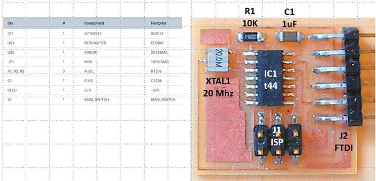
So at this point i moreless understand which components i should use. At this moment i did not know how to connect them and ever and specific which one was the purpose of the "Crystal".
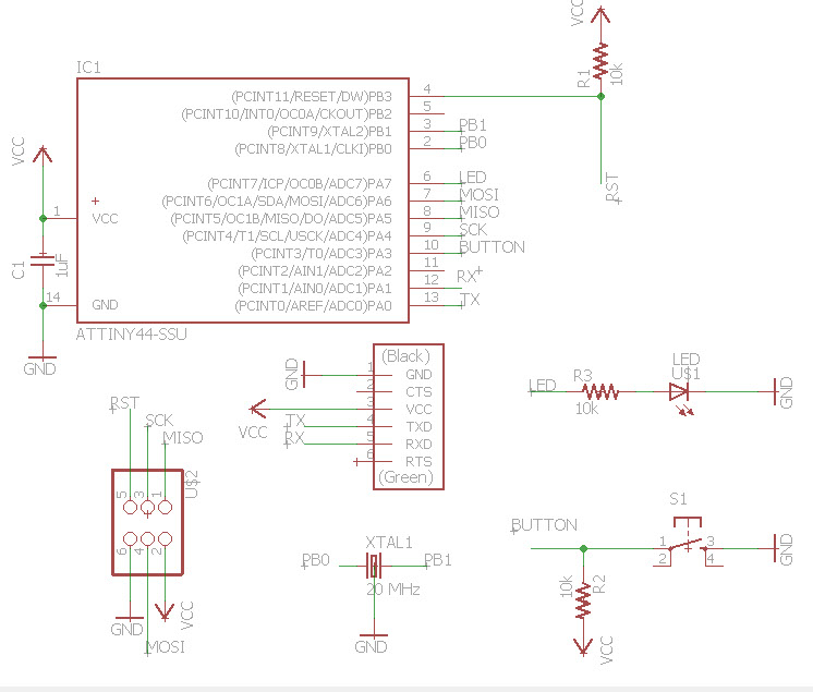
So i research some in the internet and found 2 great tutorial videos.
https://www.youtube.com/watch?v=1AXwjZoyNno
Also found another video to understand the purpose of the Crystal.. now i know that even i could use a Resonator (both give the clock to the microcomputer, a guide to proprerly function)
https://www.sparkfun.com/tutorials/95
After 8 attempts i created my schematic:
The next step is to generate the PBC, i will use the auto route option.
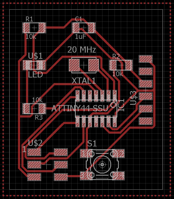
In this version (8) the values of bet classes were:
Width: 16 mil
Drill: 20 mil
Clearance: 10 mil
The drill i was going to use was 1/64 for drilling and 1/32 for cutting
After that generation, i exported as PNG file with monochrome setting and 600 dpi of resolution.
Then i loaded indo the fab modules with following default options, i just change the error to 0.1 pixels
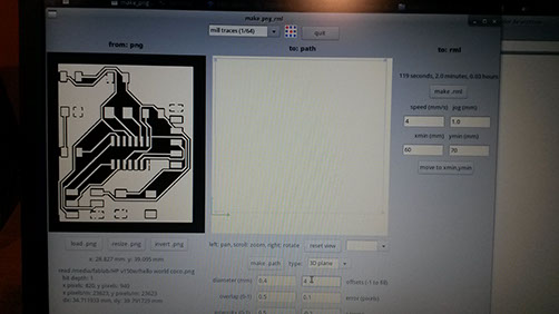
At this moment i dindt realize that i havent a problem with my png.
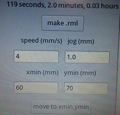
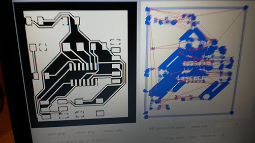
In this step i didnt realize that i was already loosing part of my design.
Please notice upper left corner. The blue lines are not complete just in the black and white png
This is a problem with the net classes options i just didnt solve.
Right now i am working in order to solve it. Because of so many concepts nwe for me i didnt finish on time. I will left the assignment in this point in order to continue with the next one.
