


W13 - OUTPUT DEVICES
Mission & initial concepts
Assignment
assignment
Add an output device to a microcontroller board you've designed and program it to do something
Concepts and Inspiration
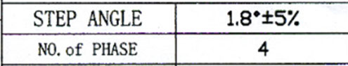
I decided to use Stepper Motor as my output device
Files i used in this assignment
Electronic code
Planning of Pinouts (ppt)
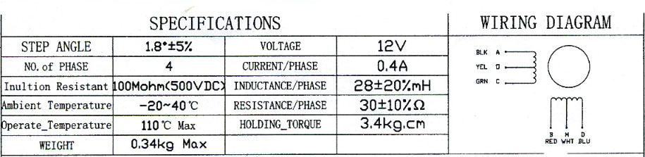
Stepper Motor
http://www.explainthatstuff.com/how-stepper-motors-work.html
The basic construction : I'm going to simplify stepper motors here to illustrate the simple, central idea: the (inside) rotor of a stepper motor turns by small, discrete amounts (steps) because the (outside) stator applies magnetic impulses that pull and push it around.
A stepper motor rotor has two back-to-back discs giving alternating left and right magnetic poles.
The rotor : The rotor itself is made from two discs, a little like gears, one of which is a magnetic north pole (red) and the other is a south pole (blue). When we put the two discs back to back, we get north and south pole teeth alternating around the edge. If you find that hard to picture, imagine your left hand is a magnetic north pole and is colored red, while your right hand is a magnetic south pole and colored blue. If you put one hand on top of the other so the fingers of one hand alternate with the fingers of the other, then look down, you'll see alternating north and south pole "teeth" (the fingers) around the edge. That's effectively what we have in the rotor of a stepper motor.
A stepper motor's rotor is made from two discs placed together so we get a series of alternating north and south poles. I've simulated the idea by coloring my hands and putting them on top of one another so the fingers alternate when viewed from above.
The stator: Around the edge of the rotor, we have the stator: in this example, four electromagnets that can be switched on and off individually. Generally the electromagnets in a stepper motor work in pairs, with each opposing pair of magnets switching on together to make a north pole at the same time, followed by the magnets at right angles, which also work together. I prefer to draw it a slightly different way, which I think is simpler and easier to understand. Exactly what switches on when depends on how many rotor teeth (steps) there are and how many electromagnet coils surround them: the geometry and alignment of a stepper motor has to be just right to make the
Best complementary video
https://www.youtube.com/watch?v=t-3VnLadIbc

Phases
In a motor, a "phase" usually means one or two opposing electromagnets that operate alternately (out of sync with one another or out of phase, if you prefer).
The motor I've illustrated up above has two phases (two pairs of electromagnets, so four electromagnets in total, arranged at 90 degrees). In a three-phase stepper motor, you might have three electromagnets arranged at an angle of 120 degrees (so three individual electromagnets, although a three-phase motor could also have three pairs arranged 60 degrees apart). A four-phase motor has eight electromagnets arranged in four pairs, with each one separated from the next by 45 degrees.
1 phase = 1 pair of electromagnets
4 phases = 4 pairs = 8 electromagnets, each one separated by 45 degrees
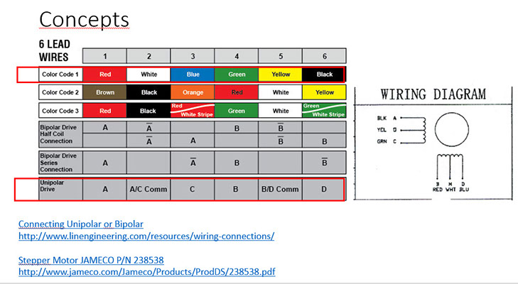
http://www.jameco.com/Jameco/Products/ProdDS/238538.pdf
Coils
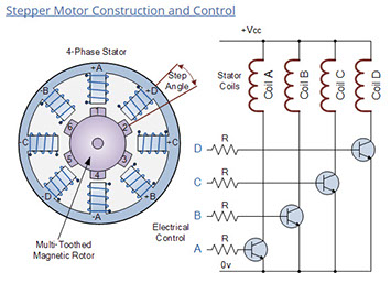
In our simple example of a variable reluctance stepper motor above, the motor consists of a central rotor surrounded by four electromagnetic field coils labelled A, B, C and D. All the coils with the same letter are connected together so that energising, say coils marked A will cause the magnetic rotor to align itself with that set of coils.
By applying power to each set of coils in turn the rotor can be made to rotate or "step" from one position to the next by an angle determined by its step angle construction, and by energising the coils in sequence the rotor will produce a rotary motion.
The stepper motor driver controls both the step angle and speed of the motor by energising the field coils in a set sequence for example, “ADCB, ADCB, ADCB, A…” etc, the rotor will rotate in one direction (forward) and by reversing the pulse sequence to “ABCD, ABCD, ABCD, A…” etc, the rotor will rotate in the opposite direction (reverse).
So in our simple example above, the stepper motor has four coils, making it a 4-phase motor, with the number of poles on the stator being eight (2 x 4) which are spaced at 45 degree intervals. The number of teeth on the rotor is 50 which are spaced 7.2 degrees apart.
Then there are 200 (50 teeth x 4 coils) possible positions or “steps” for the rotor to complete one full revolution. Therefore, the step angle above is given as: 360o/200 = 1.8o.
Full, Half and Micro steps
Obviously, the more rotor teeth and or stator coils would result in more control and a finer step angle. Also by connecting the electrical coils of the motor in different configurations, Full, Half and micro-step angles are possible. However, to achieve micro-stepping, the stepper motor must be driven by a (quasi) sinusoidal current that is expensive to implement.
It is also possible to control the speed of rotation of a stepper motor by altering the time delay between the digital pulses applied to the coils (the frequency), the longer the delay the slower the speed for one complete revolution. By applying a fixed number of pulses to the motor, the motor shaft will rotate through a given angle.
The advantage of using time delayed pulse is that there would be no need for any form of additional feedback because by counting the number of pulses given to the motor the final position of the rotor will be exactly known. This response to a set number of digital input pulses allows the stepper motor to operate in an “Open Loop System” making it both easier and cheaper to control.
For example, lets assume that our stepper motor above has a step angle of 3.6 degs per step. To rotate the motor through an angle of say 216 degrees and then stop again at the require position would only need a total of: 216 degrees/(3.6 degs/step) = 80 pulses applied to the stator coils.
There are many stepper motor controller IC’s available which can control the step speed, speed of rotation and motors direction. One such controller IC is the SAA1027 which has all the necessary counter and code conversion built-in, and can automatically drive the 4 fully controlled bridge outputs to the motor in the correct sequence.
The direction of rotation can also be selected along with single step mode or continuous (stepless) rotation in the selected direction, but this puts some burden on the controller. When using an 8-bit digital controller, 256 microsteps per step are also possible
http://www.electronics-tutorials.ws/io/io_7.html
Procedure
Output devices
The first step in this assignment was to correctly identify the activities of it:
- Selecting the output devices aligned with my final Project : Stepper Motor
- Electronics : Names, polarity and location in the PCB
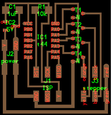
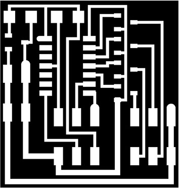
- Generating the PCB
- Soldering the components
- Understanding the operation of Stepper Motor
- Connecting and executing Proof of Concept
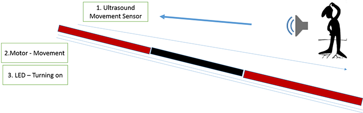
a) Selecting the output devices aligned with my final Project: As previoulsy defined, the project will try to create a preventor of security in houses at field. Some system that proactively react at strangers and give signals that make them to move away.
b) Making electronics : Understanding components, their names , polarity and location in the PCB
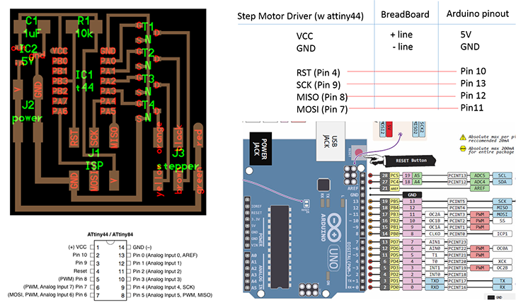
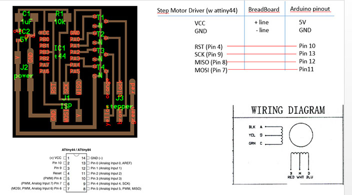
The escenario show the needed connections in order to use Arduino to program the driver (the board that will control the Stepper Motot)
As reference i used the documentation on:
http://academy.cba.mit.edu/classes/output_devices/index.html
c) Planning the connectivity : In order to propoerly connect i prepare my own review of connectivity
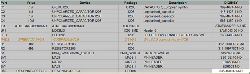
BIll of Materials
Code for programming
int motorPin1 = 13;
int motorPin2 = 12;
int motorPin3 = 11;
int motorPin4 = 10;
int delayTime = 500;
void setup() {
pinMode(motorPin1, OUTPUT);
pinMode(motorPin2, OUTPUT);
pinMode(motorPin3, OUTPUT);
pinMode(motorPin4, OUTPUT);
}
void loop() {
digitalWrite(motorPin1, HIGH);
digitalWrite(motorPin2, LOW);
digitalWrite(motorPin3, LOW);
digitalWrite(motorPin4, LOW);
delay(delayTime);
digitalWrite(motorPin1, LOW);
digitalWrite(motorPin2, HIGH);
digitalWrite(motorPin3, LOW);
digitalWrite(motorPin4, LOW);
delay(delayTime);
digitalWrite(motorPin1, LOW);
digitalWrite(motorPin2, LOW);
digitalWrite(motorPin3, HIGH);
digitalWrite(motorPin4, LOW);
delay(delayTime);
digitalWrite(motorPin1, LOW);
digitalWrite(motorPin2, LOW);
digitalWrite(motorPin3, LOW);
digitalWrite(motorPin4, HIGH);
delay(delayTime);
}
Association of my Stepper driver to my Fabuino (or Arduino)
Scenarios:
- I tested 2 scenarios:
- The first one with the Stepper driver connected to a Fabuino (FabKit)
- The second one with the Stepper driver connected to Arduino
Scenario 1 : Stepper driver connected to a FabKit
Scenario 2 : Stepper driver connected to an Arduino
