


W10 - MACHINE DESIGN
The information below is extracted from the grupal work
In this assignment my colaboration was related the research of the working requirements of the stepper motors.
Machine Design
For the automatization of the machine we will use the gestalt boards for controlling the stepper motors. Two boards will be used for controlling the 4 stepper motors of the base (2 steppers motors each) and the other to will control the motors for the XY frame. It is important to mention that for in order of one gestalt to control 2 stepper motor you have to move a small potentiometer inside the board. It can be done easily if you have an amperimeter of a electrical source that shows the current absorb by the system. For more information of electrical connections and how to make the fabnet, see the following site
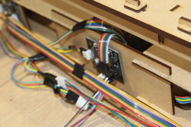
What is significante to show in this section is where are going to be located the gestalt. It was decided to put them at the back of the machine, behind the wall of the base for two main reasons:
1. The cables are hidden in that way
2. The nodes are centralized so the cables are the shortest possible.
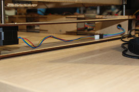
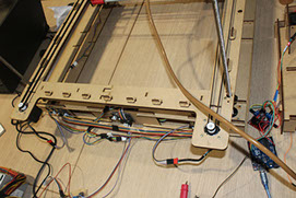
The following images exhibit the node places:
The general configuration of the nodes
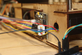
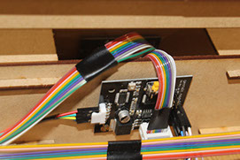
The two base motor stepper board controller and their connections
Connections of the XY controllers
Extensions were needes. We used dupont cables, but the integrarion was pretty simple.
Now comes to real issue for this... the program for the machine. We had some examples to use as guides and, lucky me, I like to program... By comparing the file examples single_node.py and xy_plotter I could understand what functions were important to change and add more code.
Because we need to control 4 nodes, we change the following definitions:
1. initController: we add 2 more axis for the Z axis.
2. initCoordinate: it was change to ['mm','mm','mm','mm']
3. initKinematics: it is veeeeeery importante because stablish how many motors are goint to be controlled. The line of code kinematics.direct(2) was change to kinematics.direct(4).
With this a calibration program was written. To see how it works please check the next video.
The next issue to solve is to read a csv file were the movements of the machine are goint to be. There are to worthy comments about this coordinates:
1. The origin of coordinates is established when the program runs.
2. Because of the CORE XY configuration, the (X,Y) coordinates need to be transform to (A,B) coordinates. For more information please visit the web site
To read csv files with python is actually very, very, veeeeeeeeery simple. We just import the csv library and put the following commands:
f = open('prueba.csv')
csv_f = csv.reader(f)
Now we have a matrix where every row is a command for the machine.
Finally we develop a program that will read a csv file and move around the working bed. .