Group Assignment:
Laser cuttertest part(s), varying cutting settings and slot dimensions
There are two approaches setting parameters while working the laser machine:
- Working slow with a low intensity :
- Will achieve a clean cut of the material
- The cutting angle will be secondary and imperceptibly
- The working time of the machine will be longer
- The thickness of the laser beam will be minimal
- Working fast with a high intensity:
- Will result a sooty cut
- The cutting angle will be noticeable
- The working time of the machine will be shorter
- The thickness of the laser beam will enlarge
There are two method testing the material tolerance (the thickness of the laser beam):
- Creating a ruler of slots in which the widest slot is wide as the material thickness, and every next slot is a 0.05mm narrower.
- Notes:
- In a machine with two separate engines for the X axis and the Y axis, each axis should be tasted.
- Also there's an importance to the material structure, for example cutting plywood with or against the fibers.

A laser cutter test for a cardboard MTM 1.4mm
- Cutting a 10*10mm square and measuring the outcome total ratio. Dividing the difference to half will give us the laser beam thickness.

Testing the tolerance of different material

The different parameters in each material
Individual Assignments:
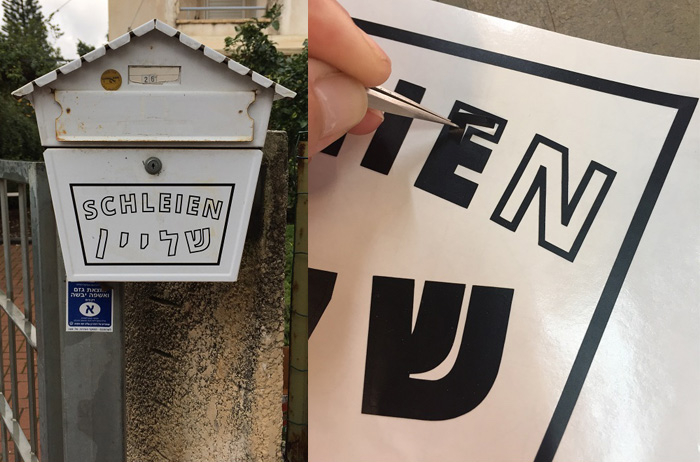
Using the vinylcutter
For this assignment I used ‘silhouette cameo’ vinylcutter to cut vinyl sticker for a mailbox
Creating a new Illustrator project - CAD sticker
- Working Process:
- Type on path

- Convert to shape
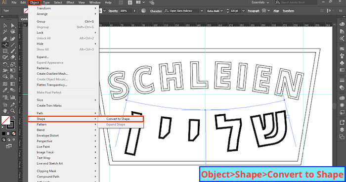
- Create outlines

- Ungroup
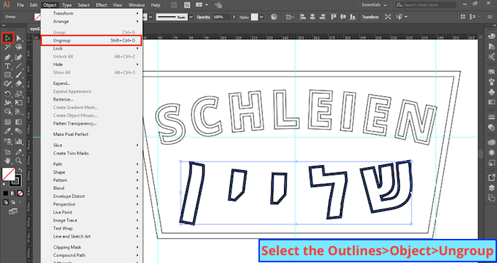
- Outline strock

- Release compound path

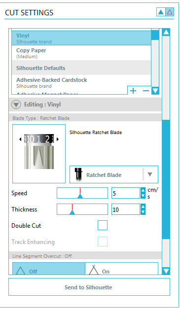
Importing the file and defining the fabrication setting
- There are three parameters needed to be settel:
- Blade depth
- Cutting speed
- Thickness
Creating a Parametric Press-Fit Kit
My goal on this assignment was to experience a new software, as I have a previous background in Grasshopper, I turn to FreeCAD. In order to achieve this I used a press-fit kit existent design, GIK by Neil Gershenfeld and focused on learning
Sketching on FreeCAD a parametric design parts for the press-fit kit, using a constraints system


Spreading the press-fit kit parts on a layout for cutting and exporting the file to the machine software & Setting the machine cutting values


My own designed KIT
For completing the assignment and designing my own kit I worked with Grasshopper. I started sketching by hand for figuring out the set of rules that my kit will include:
- The material thickness
- The laser kerf factor
- The slot depth
- The part length
- The part width
- The number of connectors
- The chamfered edge sizes
Then over grasshopper I’ve built a code from scratch with the definitions of a constructed point (X,Y,Z) and a world XY plane. Every rule that I added relate to those two initial variables. After setting the parameters of a single connector I duplicated it with a polar array.
download 3DM.File download GH.File download ai.File download DXF.File

