For this assignment I chose two kinds of inputs that would promote my final project
- Hall Effect Sensor
- Buttons
Hall Effect Sensor-
Here are some details about the sensor I’ve been using in my design:
Detailed Description-Hall Effect Sensor SOT-23W
Manufacturer-Allegro MicroSystems, LLC
Datasheets-A1324-26
Digi-Key Part Number-620-1402-1-ND
The Hall effect sensor ICs provide a voltage output that is proportional to the applied magnetic field.
About the Hall Effect Sensor board
I wanted to experiment with the hall effect sensor because of the 1st spiral development of my final project, in which I indicate the location of my game unit with the sensor and a magnet.
I based my design on the board given on the lecture page and faced some challenges during the process.
There are some differences between the image of the board and the image of the components. You can see them to the right in the traces over the sensor area as I marked with the orange circle. I started By designing a board according to the second pic assuming I can adjust it later.

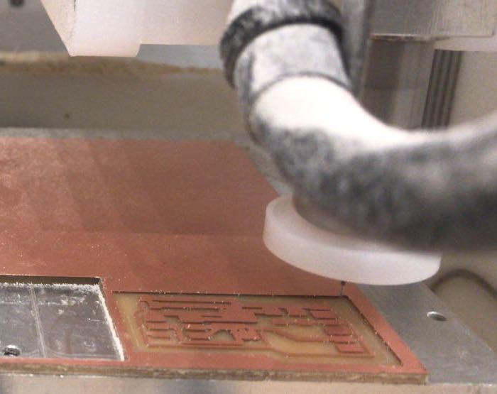
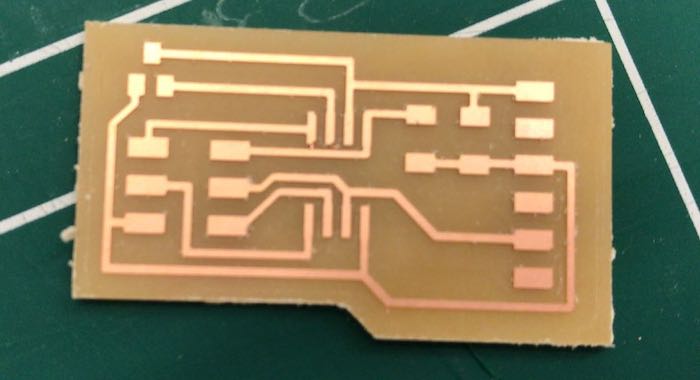
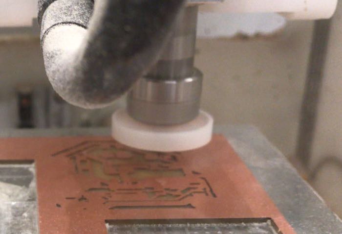
Fabricating my own board
As usual I started designing by adding the components to the schematics and repeated the protocol of naming labeling and linking the components. After finishing editing my scheme I turn to the board window for placing and designing.


The board's BOM:
- 1x ATtiny45
- 1x 2x3 pin header
- 1x FTDI header
- 1x 10kΩ resistor
- 1x 1uf capacitor
- 1x Hall Effect Sensor Single Axis SOT-23W
The board's files:
download SCH download BRD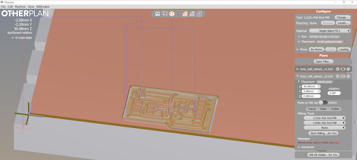
Programing the Board
I repeated the process as described in previous assignments (week 8 & week 10).
I downloaded the files from the lecture page:
Then I located them inside a pre made folder on my computer. I navigate over the terminal to the folder and ran the make -f filename and the make -f filename program-usbtiny commands.
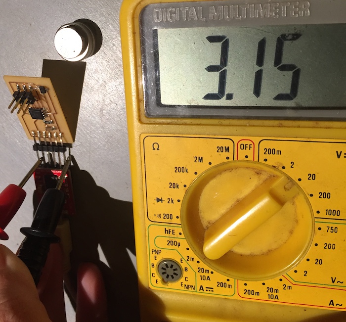
I succeeded with uploading the program, connected the board to my computer through the FTDI cable and turn to check over the serial monitor for voltage changing reads. Then I was facing a problem failing reading the sensor’s signal and couldn’t figuring what went wrong.

I talked to my regional instructor Craig that guide me finding out what was the problem. These were the steps I followed:
- Make up the board with just the FTDI and the Hall effect sensor.
- Use the multimeter in ‘beep mode’ to check that:
- There are no connections between any of the three legs on the sensor.
- The VCC on the FTDI connects to the VCC on the sensor.
- The GND on the FTDI connects to the GND on the sensor.
- That the VCC and GND do not connect to each other.
- Power the board with 5v by plugging in the Arduino (5v to vcc & gnd to gnd).
- Put the multimeter into "V⎓ 20 mode":
- Put the black probe on the gnd line between the FTDI and the sensor.
- Put the red probe on the output of the sensor (PB4 line).
- Take note of the voltage on the screen.
- Have a friend hold a magnet near the sensor, the voltage should change.
***I found out that the sensor was invalid***

Testing the sensor with Arduino
I wanted to succeed with getting an input signal from the hall effect sensor. I used another sensor and checked it directly with Arduino Uno and it worked.
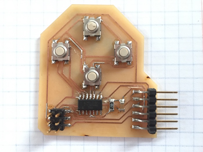
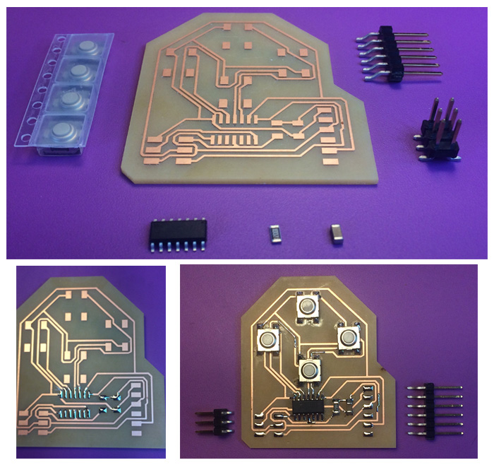
About the 4Buttons board
I’ve planned the 4buttons board thinking about future development steps of my final project, in which the move of the game’s units can be controlled. The board includes 4 buttons each one for different directions (right,left, up & down).
Fabricating my own board
On the beginning I’ve based my design on the hello button board presented in the lecture page and made some adjustments.I’ve changed the microcontroller to ATtiny 44, for achieving more inputs entries. I used the information given on the datasheet for determining which pins to use for each functions. The planning and the design were made through Eagle. Over the schematic I’ve added the components named labeled and linked them. Then over the board window I’ve ordered the components and routed between them.


The autorouter tool:
This time I’ve tried a new tool, the Autorouter, on Eagle. When the unrouted layer is selected in the layout window the unrouted traces over the board can be seen clearly. I entered the route tool menu and define the different variables to fit my neads. After choosing and setting the autorouter tool I got different solutions to my design. None of them gave a 100% result, so I had to finish the design on my own.

The board's BOM:
- 1x ATtiny44
- 1x FTDI header
- 1x 2x3 pin header
- 4x button-6mm switch
- 1x 10kΩ resistor
- 1x 1uf capacitor
The board's files:
download SCH download BRD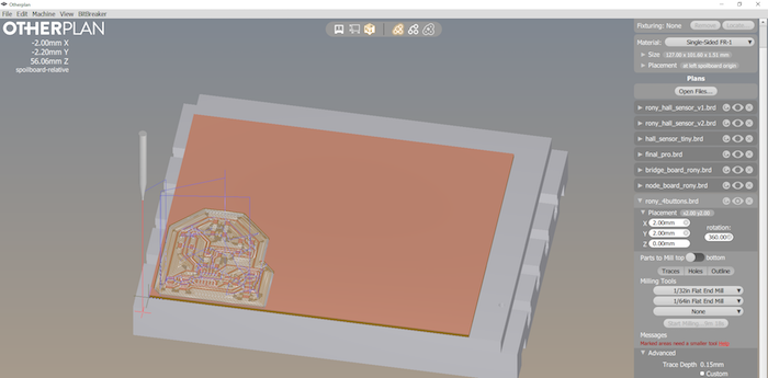
Programing the Board
I started the process with downloading both of the files given on the lecture page:
Then I located them inside a pre made folder on my computer and because the makefille and the C code needed to be adjusted I duplicated the folder. Then I’ve edit the files that they’ll suite for my new designed board. Highlighted in blue are the changes I’ve done to fit the setting to the microcontroller, Attiny 44 that I’ve used.

Over the C code I needed to set the port, direction and pins over the input and output variables. For start because of my little knowledge I used the code to communicate with only one of the buttons, so that the code will change minimally. After I made the changes I continued with the programing process. Over the terminal I navigated to the folder and ran the make -f filename and the make -f filename program-usbtiny commands. Than open the serial monitor over Arduino IDE while connecting the board through the FTDI cable. I’ve pushed the button and got the signals written in the code.

Editing the code
Over the definition area I’ve added all four buttons. Over the setup area I’ve setted the variables R, L, U and D and turn on pull-up for all four buttons.
In this main loop there are set of four
while (1)if the state of pin 0 equals (0)if int R not equals (1) only when R=(1) write ‘R’if the state of pin 0 not equals (0) R=(0)
The meaning of those four conditions is write ‘R’ once only when pin 0 is pushed down.
download c.file download make.file