About my boards
My purpose this week is to operate a small Serial Asynchronous network with using of the RS-232 standard. My small network includes one “master” which is my computer and three “slaves” one bridge board and two nodes boards. In this assignment I based on Edgar R. Aguilar Arenales, a former student in Fab Academy, designs that can be found on this page with more explanation about this week assignment.
About the network
The master, my computer, is the one which gives the instructions. Every board is being programed separately. The bridge connected through the FTDI cable to the computer and the boards connected through a communication cable which includes VCC, GND, TX and RX. Each of my boards has an id so I can send instructions addressing one and not the other. The instructions is being sent to the boards through the network and with the identification the master can tell which slave to take action.

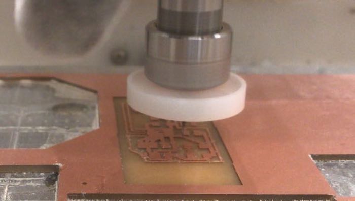
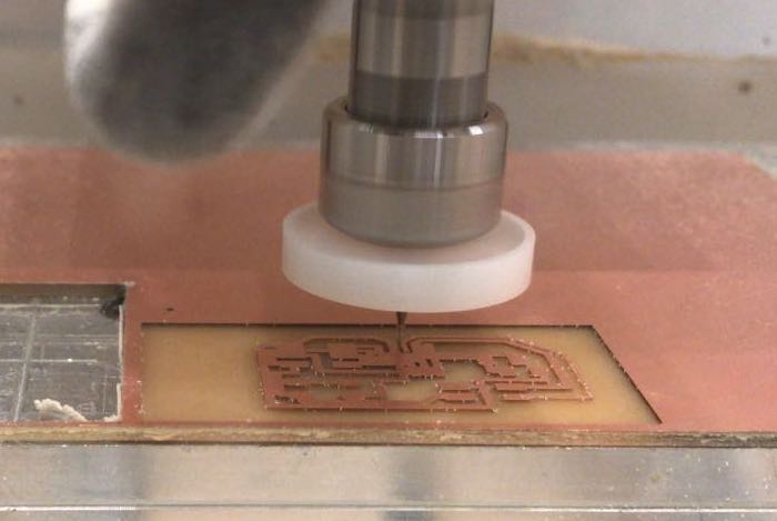
Fabrication of the boards
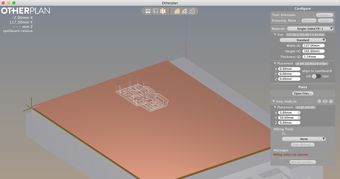
I started designing by adding the components to the schematics and repeated the protocol of naming labeling and linking the components. After finishing editing my scheme I turn to the board window for placing and designing.
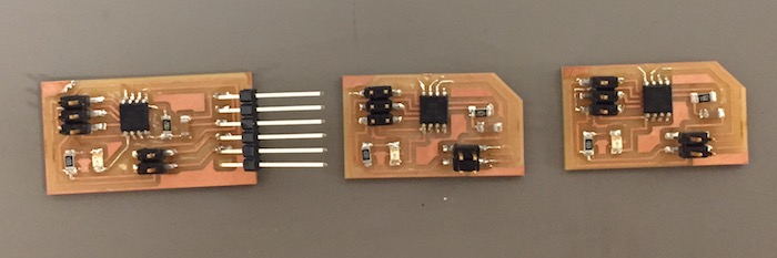
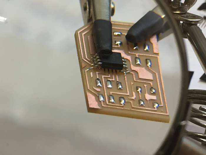
The bridge board


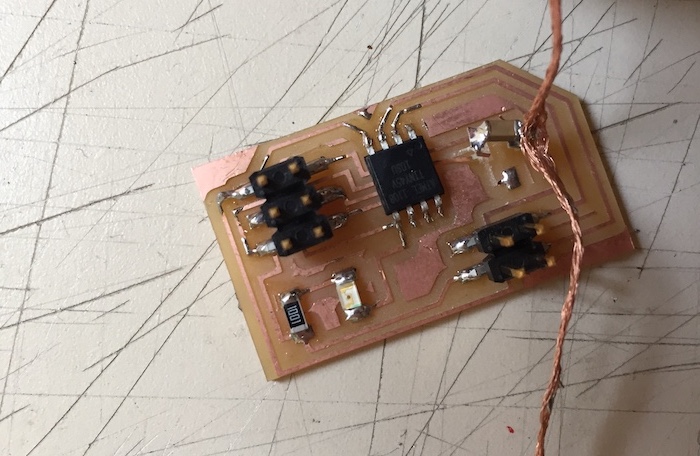
The node board


The bridge board's BOM:
- 1x ATtiny45
- 1x 2x3 pin header
- 1x 1uf capacitor
- 1x LED (Light Emitting Diode)
- 1x 10kΩ resistor
- 1x 1kΩ resistor
- 1x FTDI header
- 1x 2x2 pin header
The node board's BOM:
- 1x ATtiny45
- 1x 2x3 pin header
- 1x 1uf capacitor
- 1x LED (Light Emitting Diode)
- 1x 10kΩ resistors
- 1x 1kΩ resistor
- 1x 2x2 pin header
The boards files:
download bridg sch download bridge brd download node sch download node brd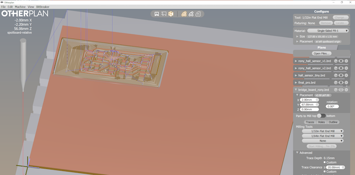
Programing the Boards
I followed the process as describe here with the exception of editing the C code from board to board. Over the C code I found the line #define node_id '0' and changed the indicator ‘0’ in every board to a different number. After finishing with uploading the programs I connected the boards with a communication cable to one another and the bridge board to the computer with a FTDI cable. I’ve opened Arduino IDE checked that the selected port appropriates and opened the serial monitor. Inside’s serial monitor the baud rate to select is 9600. Each time I typed a different number from those I programed the boards with. After pressing Enter every time, all the boards flashes once and the selected board echo back once more.

Editing the code
I’ve changed two variables, the led flash delay and the message's text.
download c.file download make.file