About my board
For this week's assignment I experienced with designing and programing a board which operate a project called Tiny CNC the Mini 3-Axes CNC v0.29 by MakerBlock. I hope this experience will provide me a backround for my final project later development.
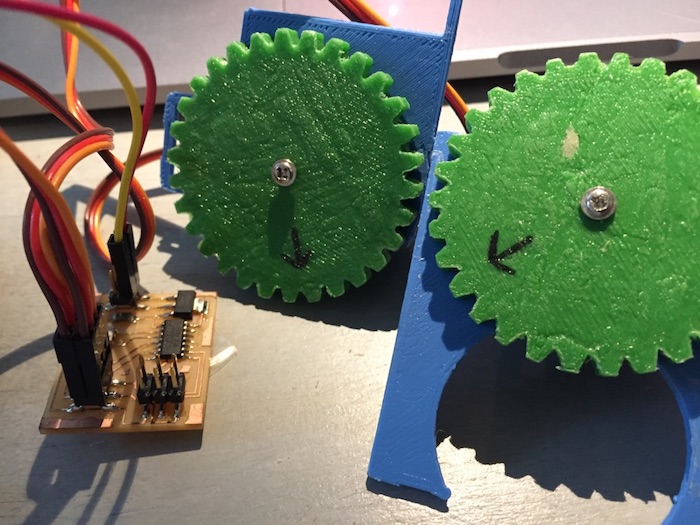
The tiny CNC device with X, Y and Z axes, includes three micro Servo motors and some 3D printable plastic parts you can download from the linked above Thingiverse page. I deal with only the X and Y axes. Handling with programing a microcontroller board to move a point on two axes by rotating the Servos.

Experiencing with Arduino
After assembling the prehead TinyCNC device I followed the instructions I found on this page.
Working process:
- wiring the Servos to the Arduino board.
- downloading these files.
- opening the MiniCNC code (located inside the MiniCNC folder) on Arduino IDE.
- checking my wiring compatible with the code.
- uploading the code to the Arduino board
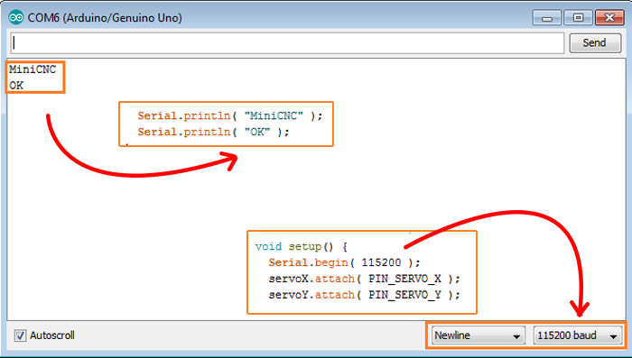
- opening the serial monitor, matching the baund definition to the code and receiving an answer.
- typing a coordinate making the ‘header’ moving on the X axis following by the Y axis.


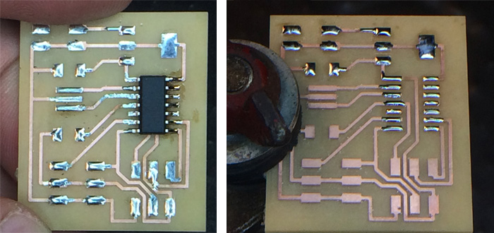
Fabricating my own board
After succeeded with programing an arduino and operating the TinyCNC I turn to designing my own board. I based my design on the Hello Servo board For a better understanding about the structure of the board and the use of the regulator I turn to compare between the microcontroller and the servo motor operating voltage through their datasheet:

working process through Eagle:
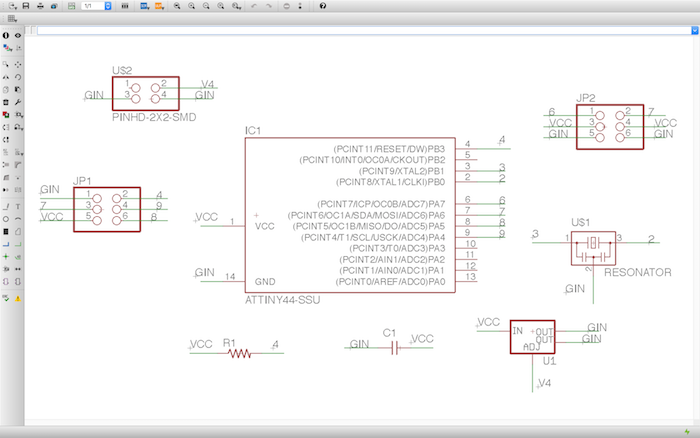
- redesigning the Hello Servo board schematic
- Adding component to the schematic
- Naming, labeling and linking the component
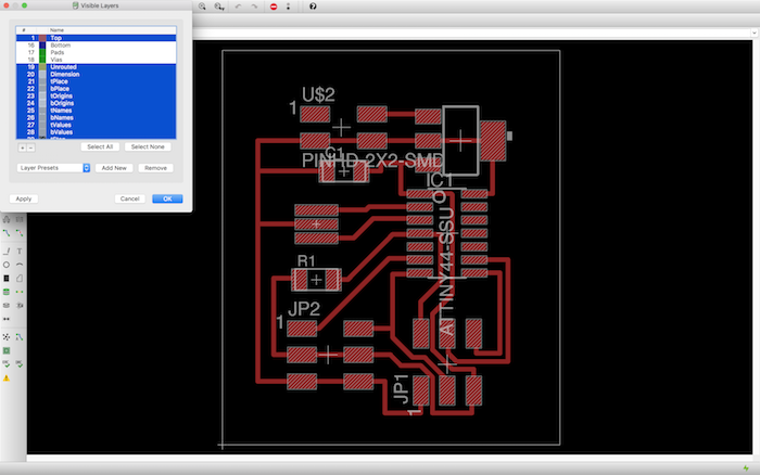
- Placing the components over the brd
- Tracing+Design rules
The board's BOM:
- 1x ATtiny44
- 2x 2x3 pin header
- 1x 20MHz resonator
- 1x 2x2 pin heade
- 1x 10kΩ resistor
- 1x 22uf capacitor
- 1x regulator IC2 5V 1A
The board's files:
download SCH download BRDMilling with Othermill & Stuffing
Setting parameter over Otherplan and the stages to complete:
- The current tool, when changing the tool test for the Z facto
- Material: kind, size and placement
- Plans: File to upload and placement
- Milling tools:
- 1/32in for surface cleaning
- 1/64in for traces milling
- 1/32in for cutout
Otherplan alerts you if there are areas which needs a smaller tool.


Programing the Board
After completing the assignment of week eight, embedded programing, the programing went smoothly. I downloaded the files from the lecture page:
Then I located them inside a pre made folder on my computer. I navigate over the terminal to the folder and ran the make -f filename and the make -f filename program-usbtiny commands. After burning the program on my board I wired both of the servos motors and connected the board to Arduino Uno as my power supply. After completing wiring I supplied power to the Arduino Uno and it worked!!

Editing the code
Over the datasheet of the servo I found explanation about what ‘ms’ stand for. I’ve wanted to create a sketch for the TinyCNC that will draw a square. First I located both X and Y axes over point 0,0 (-90° to the left). Then I moved the X axes all length that the servo unable (90° to the right). After I moved the Y axes the full length (90° to the right). For the third side I moved the Y axes back to point 0 (-90° to the left) and at last the X axes back to point 0 (-90° to the left).
download c.file download make.file
