Make and Program an ISP Programer
This week assignment was to make and program an ISP programer. I don’t have any previous background in electronics there for I turn to my team as well to my local and regional instructors for supports in the electronic challenges. This is the opportunity to thank you all.
I chose two of the given designs:
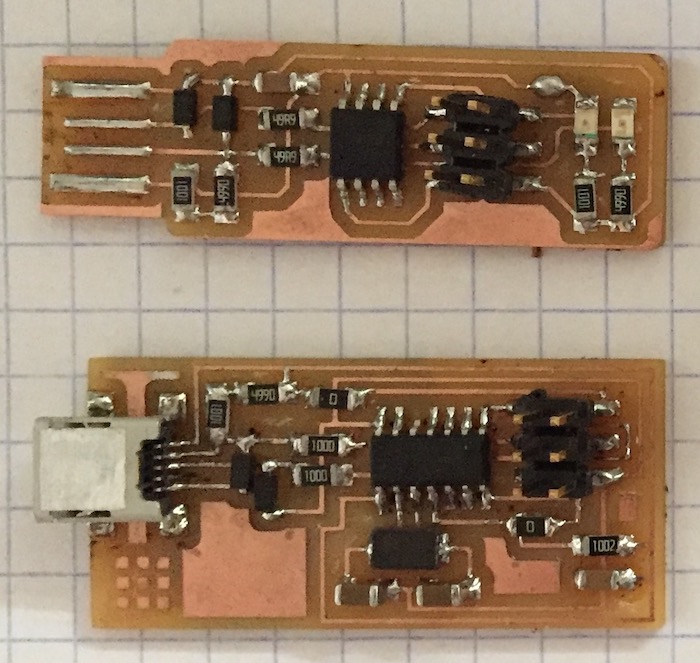
- Brian's FabTinyISP


- David's FabISP

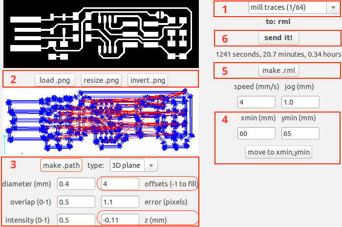
1. Working with the Fabmoduls
- Choosing a milling bit
- Loading a PNG file (resizing or inverting it)
- The milling course:
- Setting the amount of offsets
- Setting the 'Z' depth
- Hitting the 'make .path'
- Setting the begin of milling 'X' & 'Y' coordinates
- Make .rml
- Send it!
***I used an old version of Fab Modules because of a poor networking conection***
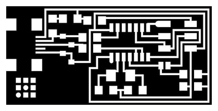
2. Milling with the Roland Modela MDX20 Milling Machine

3. Checking the traces for any short circuits
4. The board's BOM:
- 1x ATtiny45
- 2x 1kΩ resistors
- 2x 499Ω resistors
- 2x 49Ω resistors
- 2x 3.3v zener diodes
- 1x red LED
- 1x green LED
- 1x 100nF capacitor
- 1x 2x3 pin header
5. Soldering

Programing the board
At this stage I focused on Brian’s FabTinyISP board, following the instruction from this tutorial.
Here are the working steps for the programing:- Setting the developing environment
- Programing:
- Downloading and running the firmware
- Updating the firmware
- 'Make flash'
- Identifying the ISP

Downloading and running the firmware

'Make flash'

Identifying the ISP