Objectives:
- read a microcontroller data sheet
- program your board to do something, with as many different programming languages and programming environments as possible Intro, Design, Programming Arduino Programming C, Downloads
Intro
To complete this week i had to build an ATtiny44 board because during week 6 i developed an ATxMega board instead of an ATtiny one.
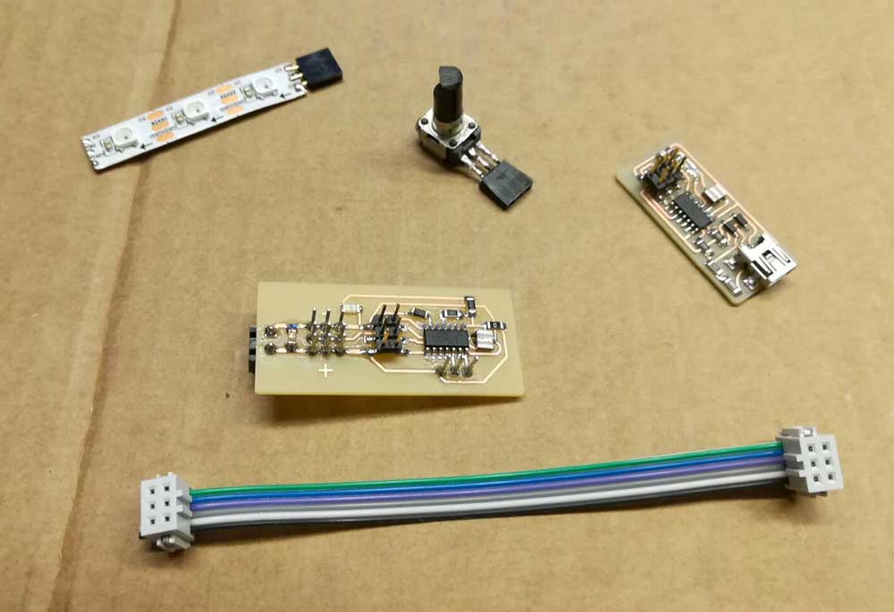
In our lab we have a delta printer with some Neopixel LED strips but they have never been connected so i made a board for them.
- Neopixel: https://www.adafruit.com/products/1461
- WS2812 Datasheet: https://cdn-shop.adafruit.com/datasheets/WS2812.pdf
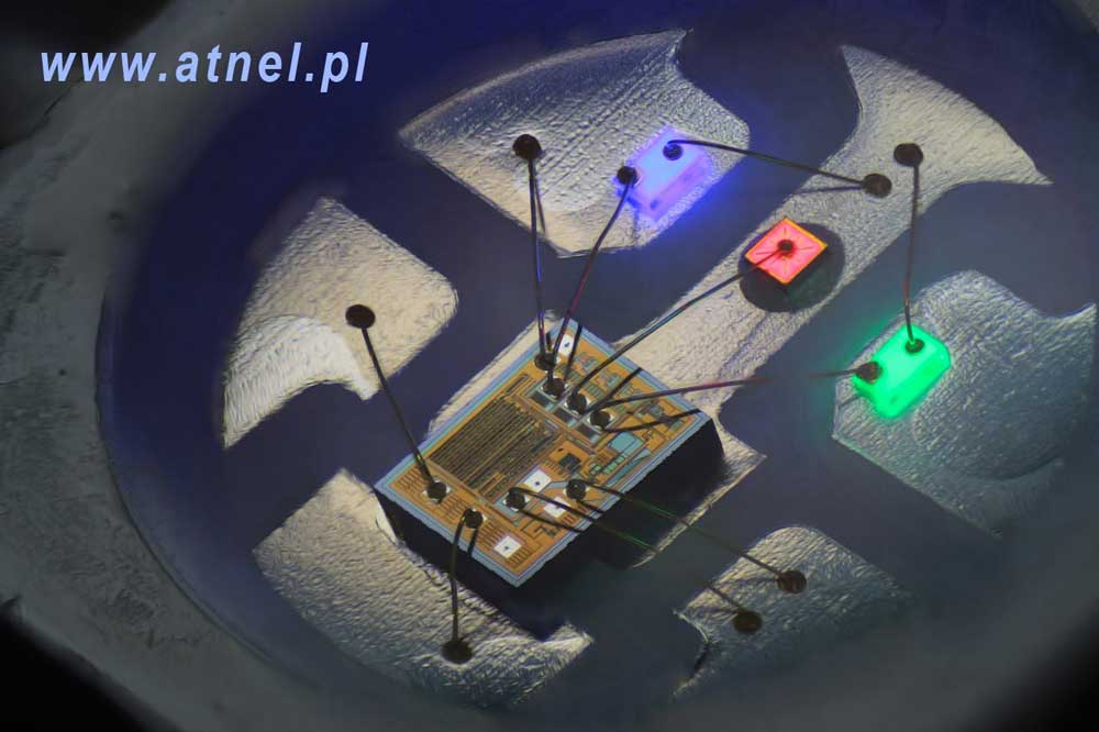
Neopixel are not normal RGB LEDs but inside they have an integrated circuit, WS2812, the latter take care of choosing the color of the LED.
Every LED have an input and an output pin, they are serialized connecting the output of the first to the input of the next and so on.
Design
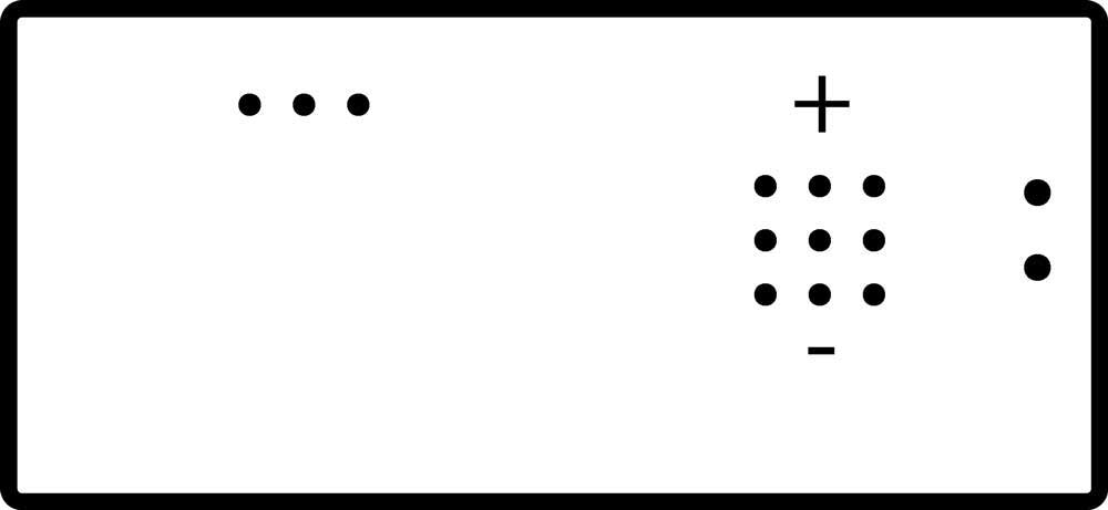
The board have 3 output header ( for the 3 strips on the 3d printer ) all connected to the same PWM output pin of the ATtiny ( pin #6 named PA7 ) and an analog pin to connect a potentiometer which will regulate the brightness or the color of the strips.
I designed the board with EAGLE, created the gcode with the mods.cba.mit.edu and etched/cutted the board with a Roland SRM-20 cnc.
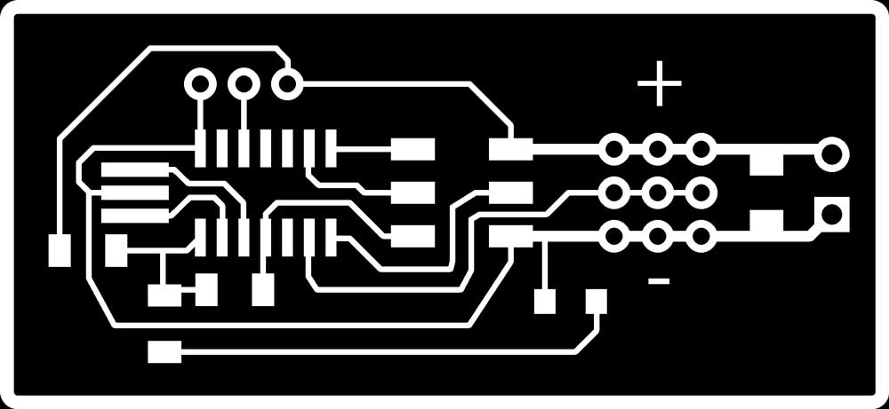
After soldering the board i realized that i forgot to place a resistor between the PA7 pin and led output so i used a cutter to separate the bus and i soldered a resistor.
Programming with Arduino
To test if everything was working i connected the ATtiny44 board to the FabOptimus ISP programmer i made during week 4 and loaded the arduino bootloader into the board.
Before loading the bootloader i “installed” the ATtiny boards.txt through the Arduino IDE’s Board Manager. After i downloaded and installed the FastLED library http://fastled.io/.
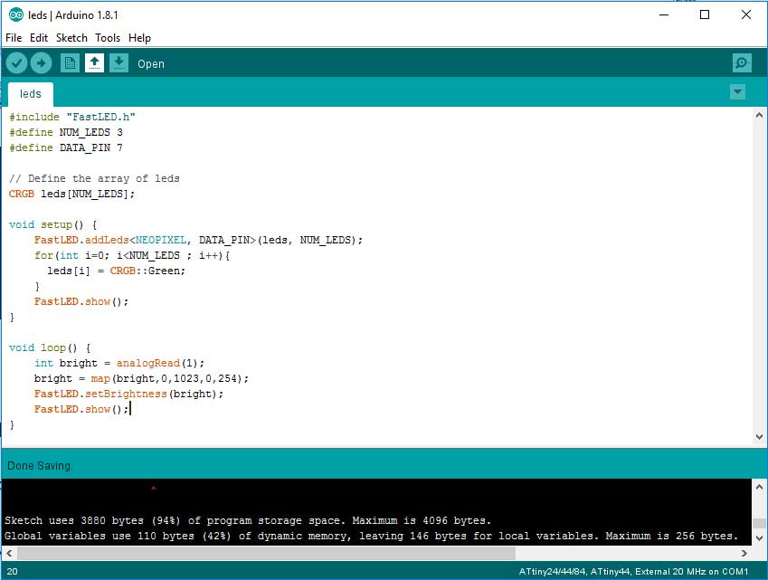
I created a simple sketch to light every led at a fixed RGB color ( green ) and change the luminosity through the potentiometer. To test the board i used a spare 3 LED Neopixel strip.
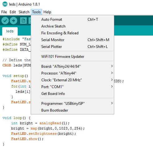
Before uploading the code i had to select from the Arduino IDE’s “tool” dropdown menu the following settings:
- Board: ATtiny 24/44/84
- Processor: ATtiny44
- Clock: External 20MHz
- Programmer: USBtinyISP
As you can see from the image below the sketch + the bootloader take 94% of the ATtiny44 space ( 4Kb total ) which is a lot!!
Programming with C
From the previous weeks i had the avrdude and gcc environment already setupped.
I found the WS2812 library here https://github.com/cpldcpu/light_ws2812
To convert the Arduino code to C code i had first to understand how the ATtiny’s ADC is handled.
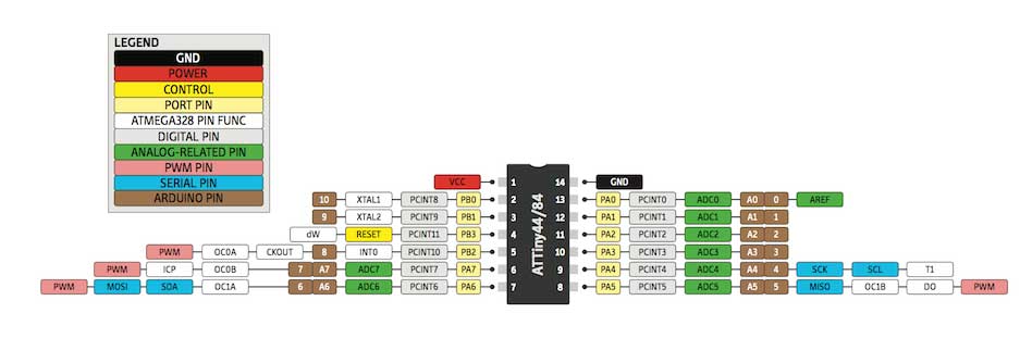
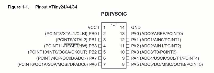
All the I/O pins of the ATtiny44 have multiple functions ( you can see them in the image above ) and they are “grouped” into ports.
Specifically the tiny44 have PORT A and PORT B each port have 3 registers: DDR, PORT and PIN. They are 8 bit registers ( attiny44 is 8bit architecture ) and each bit correspond to a pin of the attiny.
- DDR is read/write type and handle the direction of the pin ( 0 mean input , 1 mean output ).
-
PORT is read/write type:
- If the DDR of the pin is an Output, writing 1 to PORT sets the pin HIGH and writing 0 sets the pin LOW. Reading the DDR returns the state of the pin.
- If the DDR of the pin is an Input PORT turn on or off ( 1/0 ) internal pull-ups resistors. Reading the DDR tell whether the pull-ups are on or off. - PIN is read only, it’s used to read the input value of the pin.
To use the ADC we have to configure 2 registers:
ADMUX ADC Multiplexer Selection Register (8 bit register)
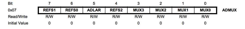
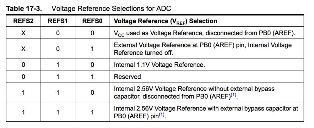
REFS0, REFS1 and REFS2 are used to select the reference voltage, the table below shows the available combinations.
In my case i used the internal 2.56V reference voltage.
ADLAR - ADC Left Adjust Result is a bit used to Left or Right adjust the ADC output. Write one to left adjust or zero to right adjust.
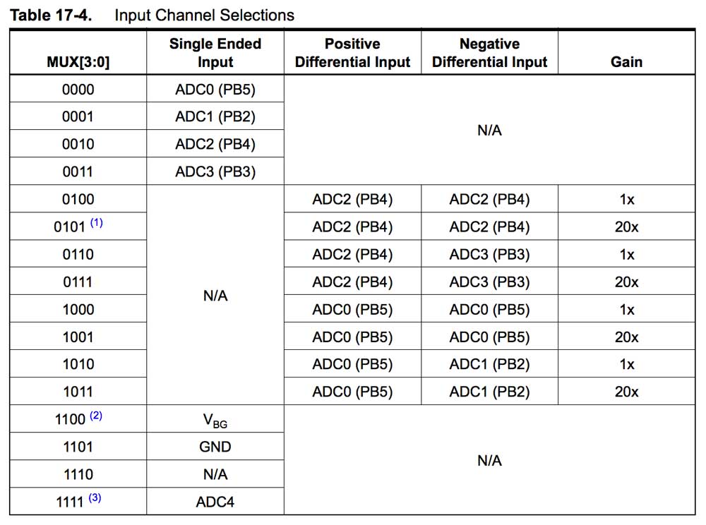
MUX[3:0] - Analog Channel and Gain Selection Bits are used to select the pin we want to read the analog input and the gain.
ADCSRA ADC Control and Status Register A (8 bit register)
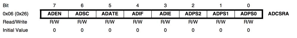
- ADEN - ADC Enable is a read/write register and it’s used to turn on and off the ADC. By reading the register we can understand if the adc is on or off.
- ADSC - ADC Start Conversion it’s used to tell the ADC to start converting. By writing 1 to the register it stay at 1 all the conversion long then go back to zero when the conversion is completed.
- ADATE - ADC Auto Trigger Enable its used to let the ADC sample using an external input clock. The ADC sample every time the clock signal goes high. To select the srouce you have to write the bit ADTS in the register ADCSRB.
- ADIF - ADC Interrupt Flag The register goes to 1 when the conversion is completed.
- ADIE – ADC Interrupt Enable is used to enable the ADC interrupt by setting the bit to 1.
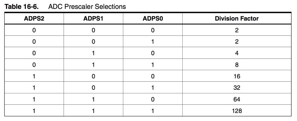
- ADPS2:0 – ADC Prescaler Select Bits it's used to set the ADC clock frequency, the datasheet recommends a sampling frequency between 50 and 200 kHz. The more you sample fast, the less accuracy you have. In my case i've an external clock of 20Mhz but i’d rather having more accuracy than having speed so i used a division factor of 128. ( 20000 / 128 = 156kHz ) -> (1 << ADPS2) | (1 << ADPS1) | (1 << ADPS0).
Delta_lights.c
Here’s the resulting code:
#include < util/delay.h >
#include < avr/io.h >
#include < avr/interrupt.h >
#include "light_ws2812.h"
#define NUM_LEDS 6 // Total strip LED number
struct cRGB led[NUM_LEDS];
int brightness = 0; // Variable to hold the brightness
uint8_t ADCLow;     // ADCL variable
uint16_t ADCFull;   // ADCL + ADCH variable
int main(void)
{
  int i = 0;
  ADMUX |= (0 << REFS0); // set the voltage reference
  ADMUX |= (0 << REFS1); //
  ADMUX |= (0 << ADLAR); // left adjust the result
  ADMUX |= (0 << MUX3) | (0 << MUX2) | (0 << MUX1) | (1 << MUX0); // select the ADC pin ADC1 PB2
  ADCSRA |= (1 << ADEN); // Enable ADC
  ADCSRA |= (1 << ADPS2) | (1 << ADPS1) | (1 << ADPS0); // prescaler to 128
  while(1)
  {
    ADCSRA |= (1 << ADSC); // Start the conversion
    while (ADCSRA & (1 << ADSC)); // Wait till the conversion is done
    ADCLow = ADCL; // get the ADCL 8 bits
    ADCFull = (ADCH<<8 | ADCLow) / 4;
    /* 16 bit variable, shift the ADCH to the 9th and 10th position and append the 8 bit ADCL
     I divided the 10 bit -> 0-1024 by 4 to get 0-256 which is the range of the RGB led  */
    for(i=0; i<NUM_LEDS;i++){        // Write to each led the current brightness
      led[i].r=0;
      led[i].g= ADCFull;
      led[i].b=0;
      ws2812_setleds(led,NUM_LEDS);
    }
  }
}
I edited the Make file i found inside the ws2812 library to fit my processor, clock speed and programmer.
F_CPU = 20000000
DEVICE = attiny44

CC = avr-gcc

LIB       = light_ws2812
PROJECT  = Delta_lights
DEP     = ws2812_config.h Light_WS2812/light_ws2812.h

CFLAGS = -g2 -I. -ILight_WS2812 -mmcu=$(DEVICE) -DF_CPU=$(F_CPU)
CFLAGS+= -Os -ffunction-sections -fdata-sections -fpack-struct -fno-move-loop-invariants -fno-tree-scev-cprop -fno-inline-small-functions
CFLAGS+= -Wall -Wno-pointer-to-int-cast

LDFLAGS = -Wl,--relax,--section-start=.text=0,-Map=main.map

hex:  $(PROJECT)

$(LIB): $(DEP)
  @echo Building Library
  @$(CC) $(CFLAGS) -o Objects/$@.o -c Light_WS2812/$@.c

$(PROJECT): $(LIB)
  @echo Building $@
  @$(CC) $(CFLAGS) -o Objects/$@.o Examples/$@.c Light_WS2812/$^.c
  @avr-size Objects/$@.o
  @avr-objcopy -j .text  -j .data -O ihex Objects/$@.o $@.hex
  @avr-objdump -d -S Objects/$@.o >Objects/$@.lss

.PHONY: clean

clean:
  rm -f *.hex Objects/*.o Objects/*.lss

program: $(PROJECT).hex
  avrdude -p t44 -P usb -c usbtiny -U flash:w:$(PROJECT).hex
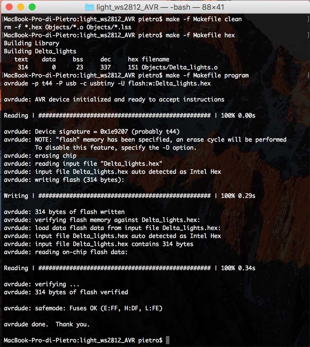
After i ran the following commands from the shell:
make -f Makefile clean      // clean previous builds
make -f Makefile hex         // build the hex file
make -f Makefile program  // flash the hex to the board
Video of the result:
Conclusions
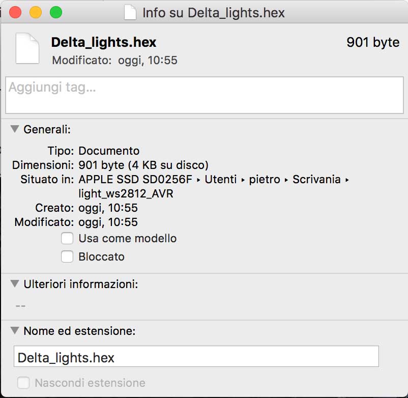
As i showed before the arduino bootloader + led code almost filled the attiny44 memory, the C hex instead only seize 900 byte out of 4kb programmable memory ( 25% ).
Arduino high level libraries provide an easy and fast way to achieve the desired result but in some cases, where memory or speed matter, coding directly in C is the way.