Objectives:
- Test the design rules for your printer(s) (group project) External Link
- Design and 3D print an object (small, few cm) that could not be made subtractively 3D Modelling 3D Printing,
- 3D scan an object (and optionally print it) 3D Scanning 3D Printing,
Intro
The assignment of the week was to test the limits of one of the printers we have in our lab and to scan a small object.
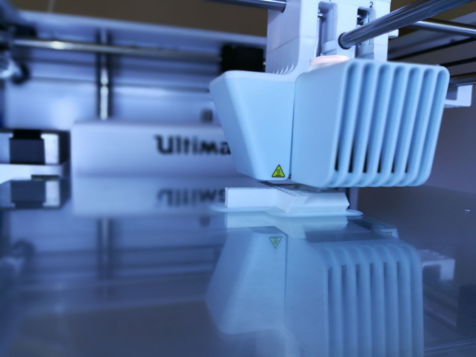
In our lab we tested the Ultimaker 2 3D printer and you can find the group test here
Link
3D Modelling
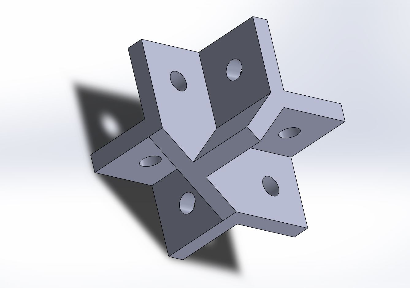
This week our instructor was building a custom 3D printer using Bosch-Rexroth aluminium profiles and he needed something to keep them together. ( Link to the product page ).
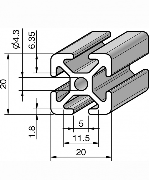
The profiles measure 20x20mm and have four 6mm T-Slots, one on each side. If you insert T-Nuts inside the slots you can screw things to the profile.

To design the part i used Solidworks 2016.
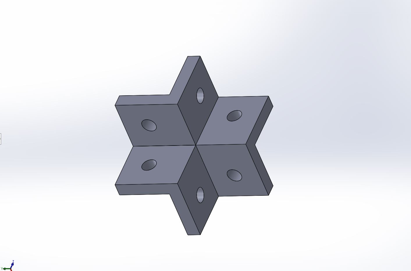
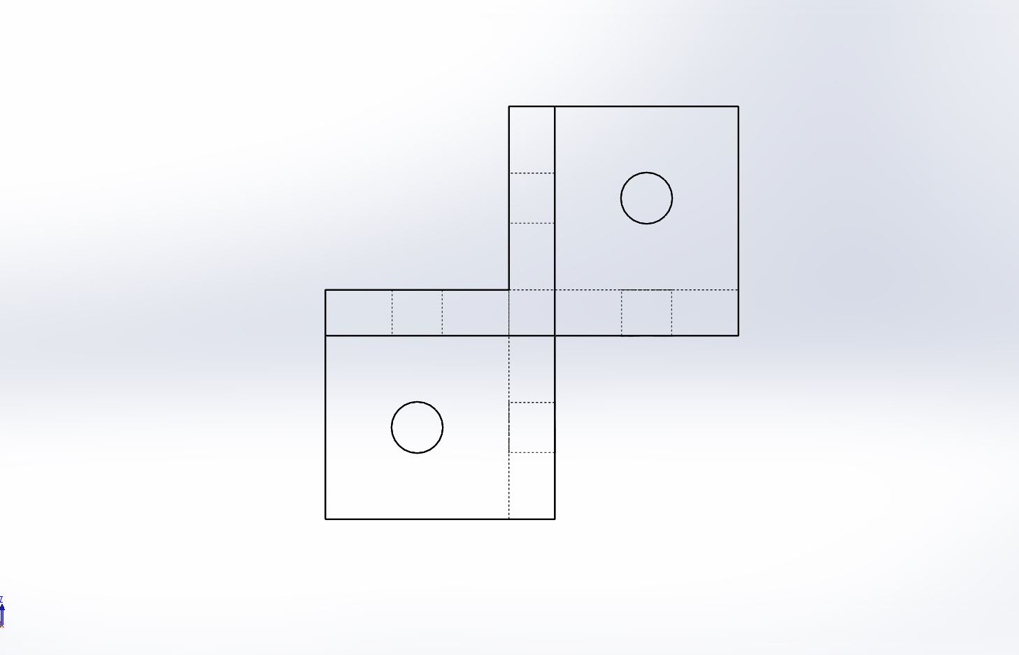
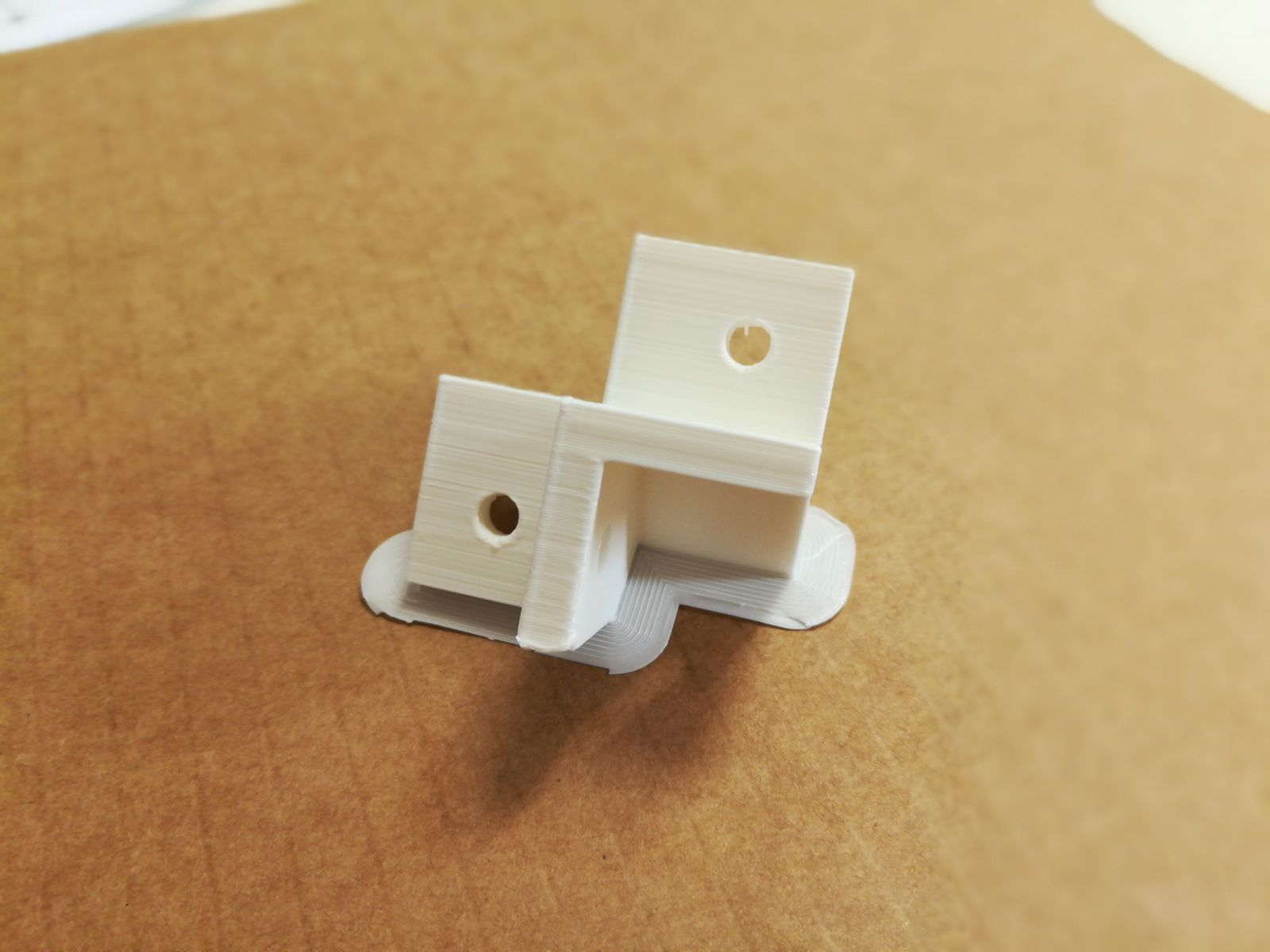
The support i created hold 3 different orthogonal profiles. I designed the touching part to cover entirely the profile side and in the middle it has a 5mm hole so you can screw it.
3D Printing
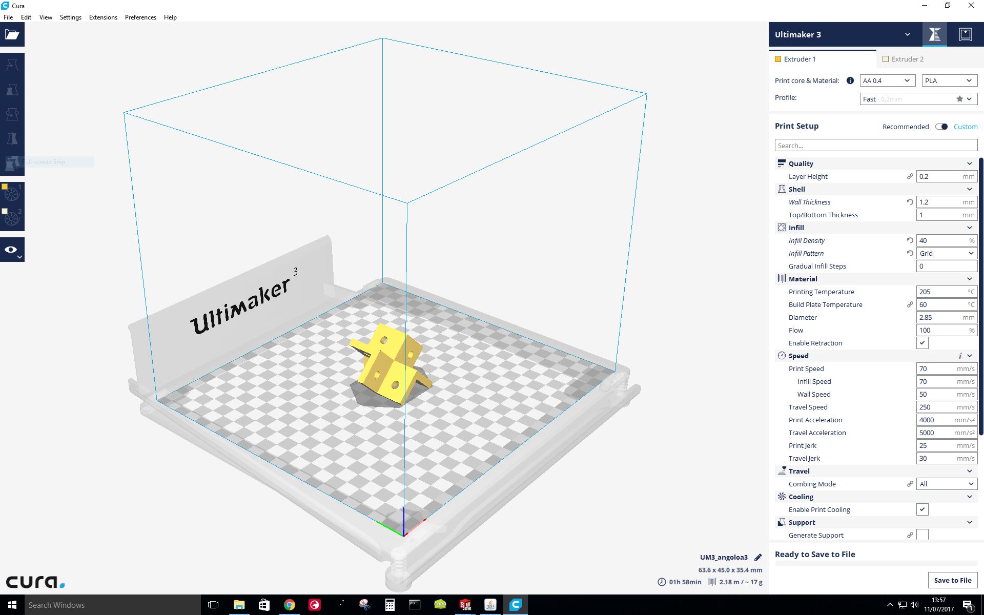
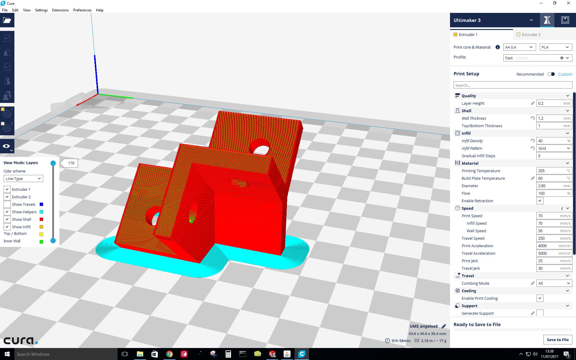
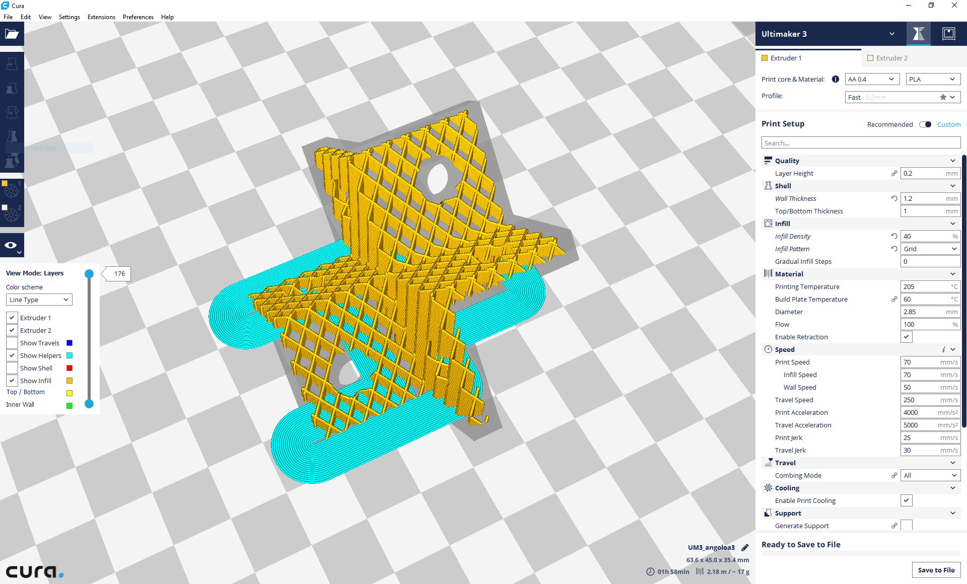
To print the part i used the Ultimaker 3 3D printer and i generated the file using Cura ( Ultimaker Software ). I placed the object so that it doesn’t need supports because the max overhang is 45°. I used layer height of 0.2mm to keep the printing time low and to have a better bonding, on the other hand a 0.1mm layer height would have produced a better finish.
Since it's a structural part i used 1 mm top and bottom solid layers and 1.2mm outer shell in addition i used a really high density infill of 40%.
The print took about 1 hour and 40 mins, the result is very nice, just a bit melty on the highest point of the overhang.
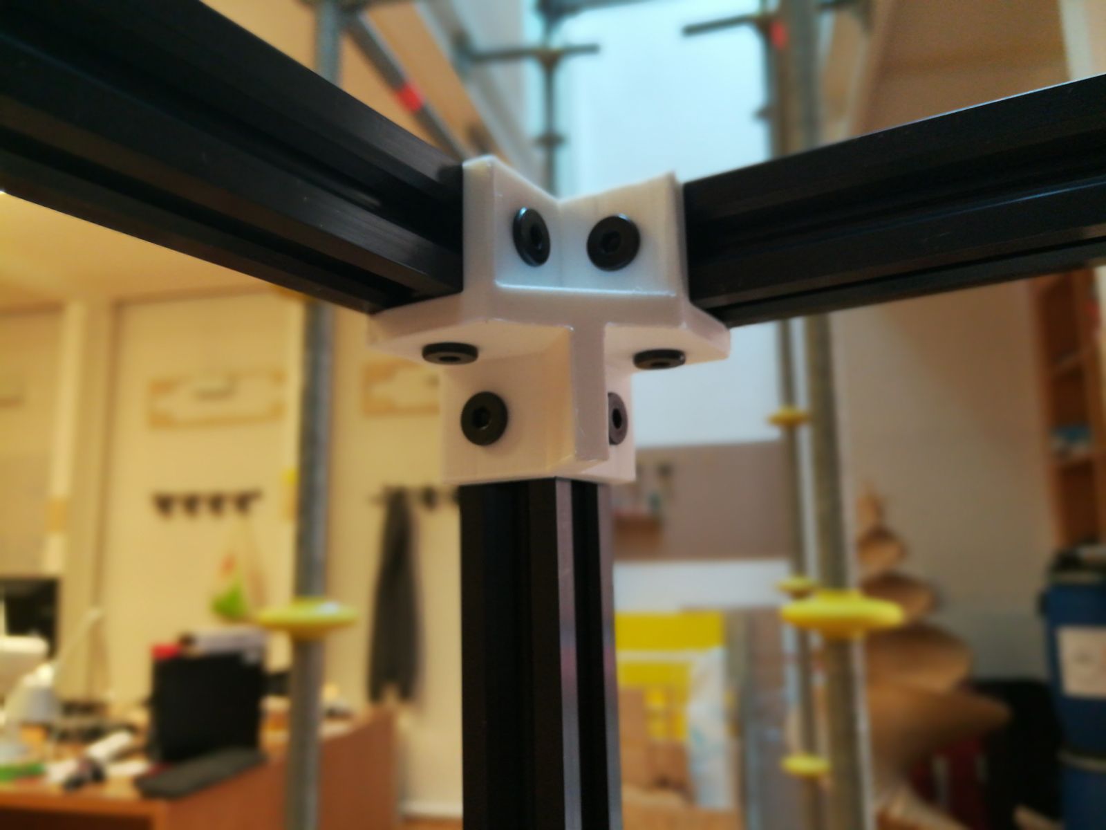
Here you can see the part mounted on the profiles.
At the end i think with a professional 5 axis milling machine you can achieve the same result but definitely not with the 3 axis shopbot we have in our lab.
3D Scanning
The scanner we have is a professional one which use Structured Light meaning it project small light lines onto the object and two cameras capture how the light “bend” on the object.
The name of the scanner is Scan in a Box https://www.scaninabox.com/
We keep the scanner in a dark environment to achieve better results.

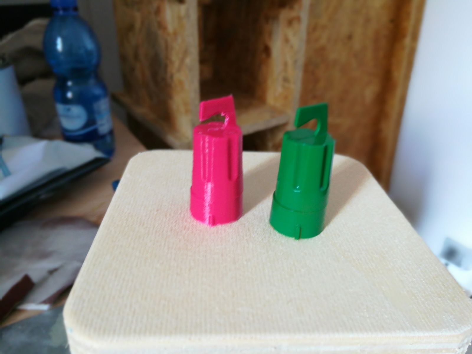
I decided to scan the glue cap but, since it was very dark, i painted it with green spray.
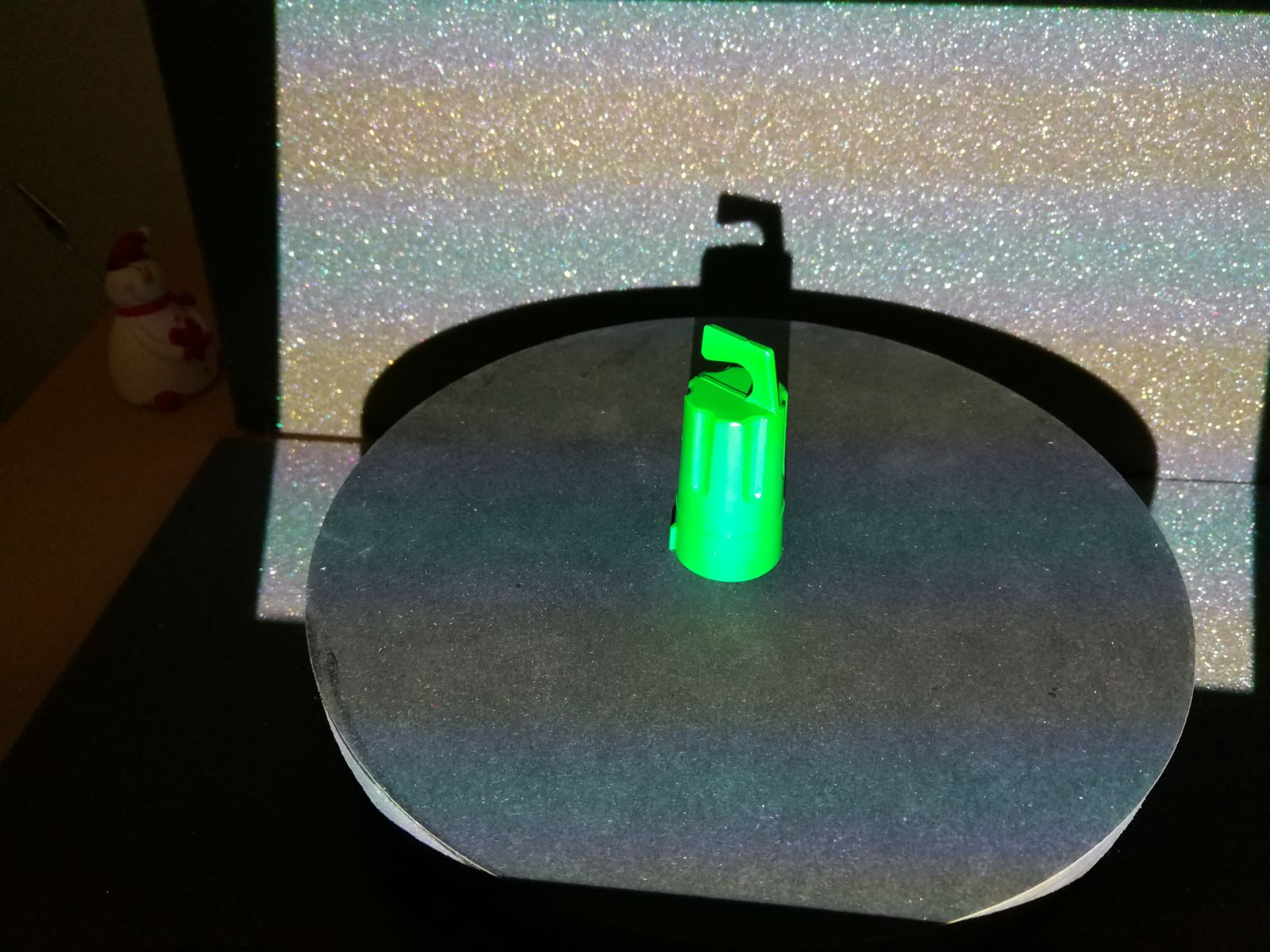
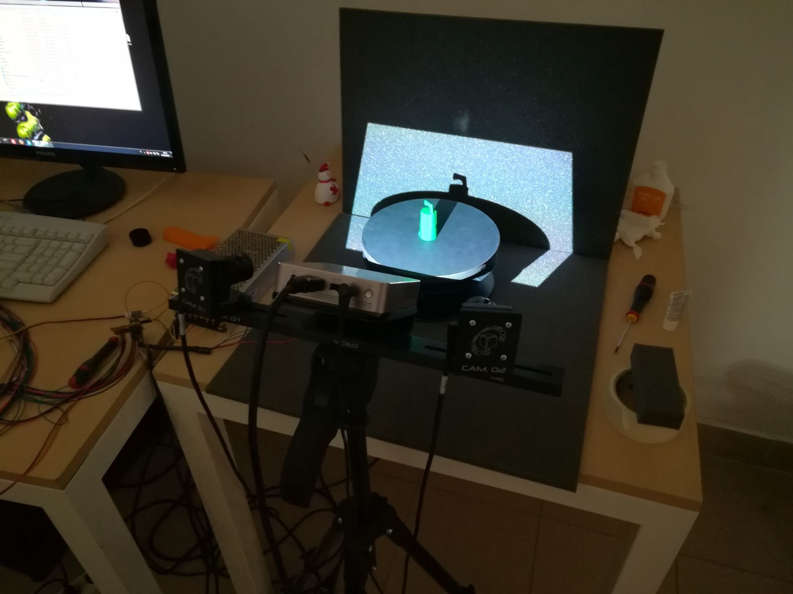
As you can see from the photo above the object is positioned in a rotating platform ( our instructor made ) which rotate by 26° each time you press a button, so you can capture 14 scan each turn.
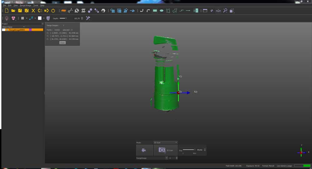
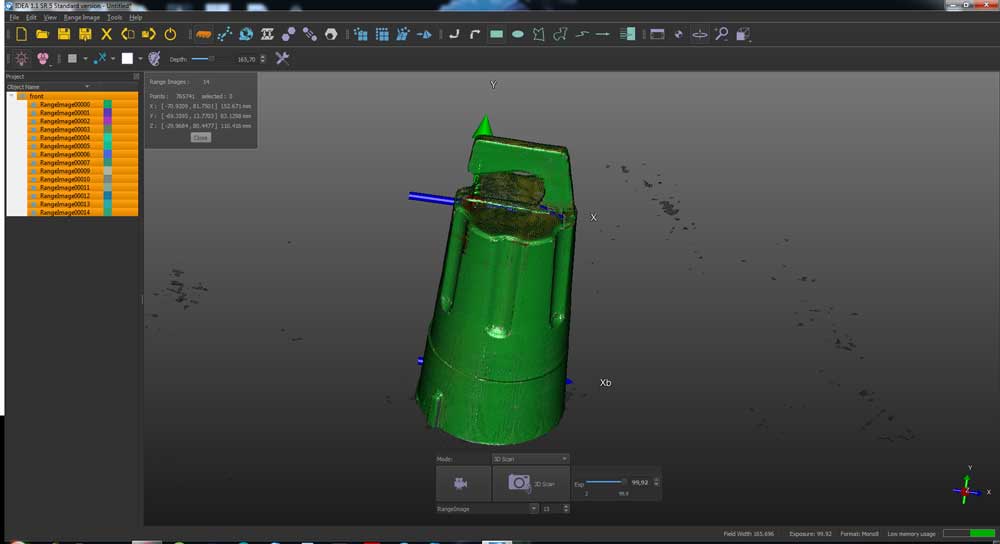
The software used to scan is proprietary from Scan in a Box and its name is IDEA.
The workflow is very simple, you press the SCAN button on the IDEA interface, the scanner takes 5/6 seconds to capture the model then you press the rotating platform button to turn the model.
I repeated this procedure 14 times till the model was fully turned.
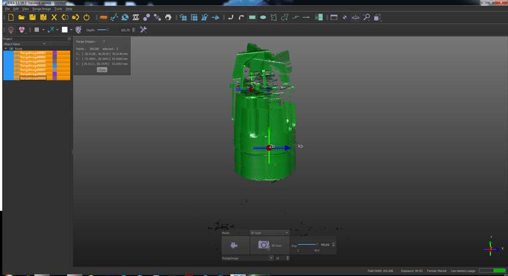
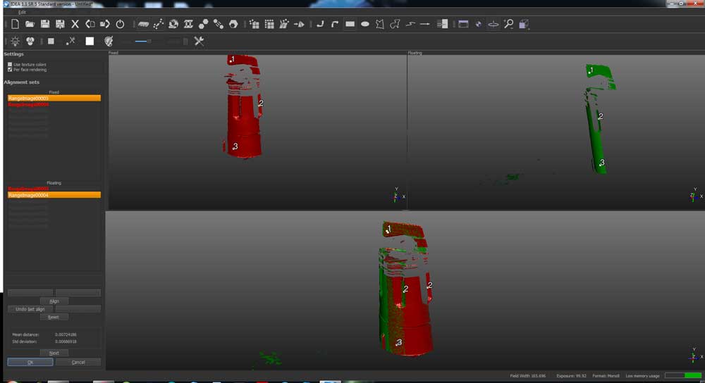
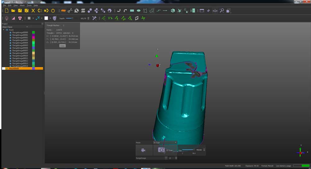
After i aligned the 14 captures by selecting the first one as fixed and “suggesting” three alignment points on each other capture to the software, then it automatically aligned them.
Next i used the mesh repair tool to smooth out the object and gap the holes.
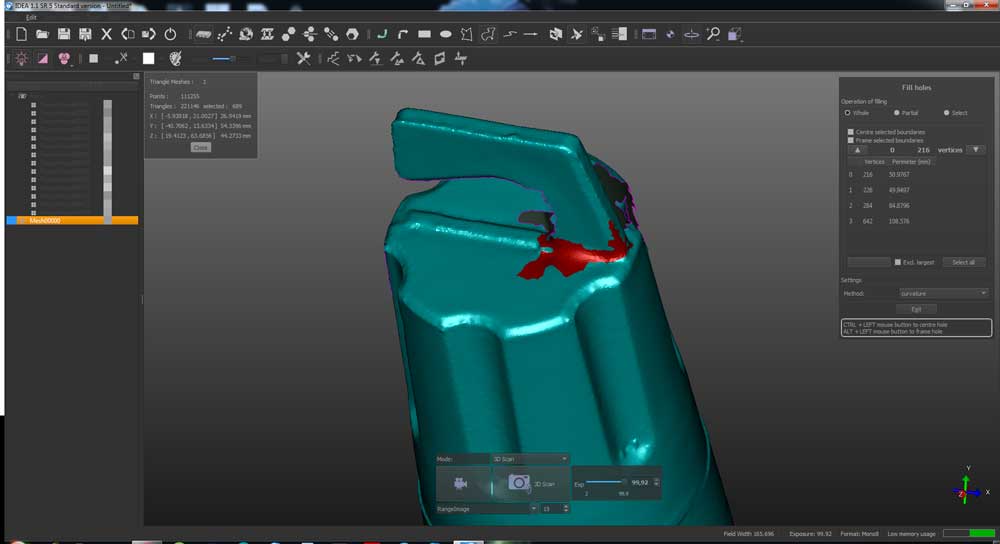
Finally i exported the mesh as STL, below the model.
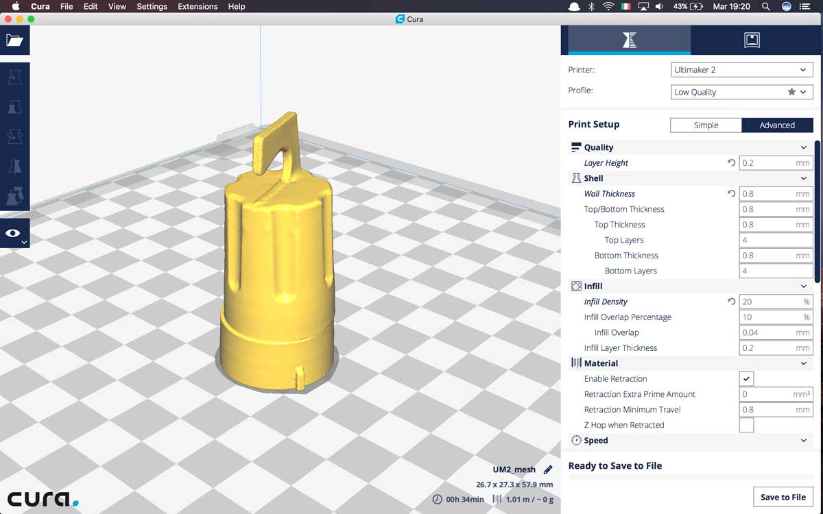
3D Printing
I loaded the mesh on Cura to slice it and print it, i selected 0.2 mm layer height and 20% infill.
I also had to use supports to the bridge on top of the cap.
On the left the printed version and on the right the original one.
It’s impressing how the scanner successfully captured all the small details and how accurate is the dimension.
( I didn't manually scale the model to fit the original ).