Objectives:
- Build a custom electronics for the robot Design, Milling and Soldering, Testing Download
Design, Milling and Soldering
To successfully control the robot i designed a small atmega328p based board.
The board feature an high voltage input ( up to 18v ) regulated down to 5v with a voltage regulator ( 1A max ). The voltage regulator will take care of powering the microcontroller and the two servo motors.
The board also have a power MOSFET which i will use to control the two DC motors that will make the robot roll.
It also have a piezo buzzer output, the ISP header exposed to program the board and the FTDI headers to test the serial connection and connect the bluetooth.

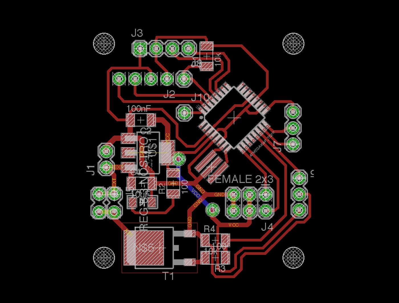
As you can see from the board image i had to use a small jumper ( blue ) to keep the board size small.
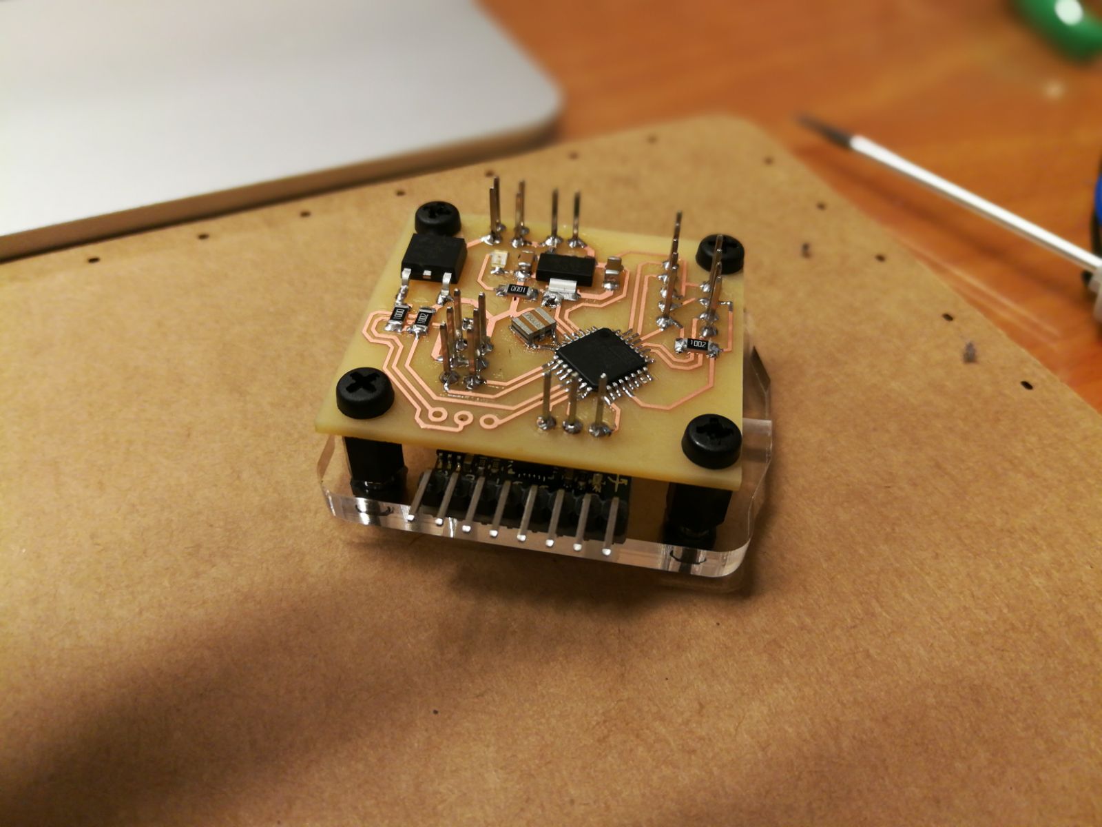
I milled the board using a Roland SRM-20, 1/64 end-mill to cut the etching and 1/32 for the holes and outline.

I cleaned the board with alcohol to remove the milling dust and the grease.
After i soldered the board and tested it using the arduino IDE, since i used the 8 MHz resonator i had to use the Lilypad 8Mhz 328p to compile the sketches.
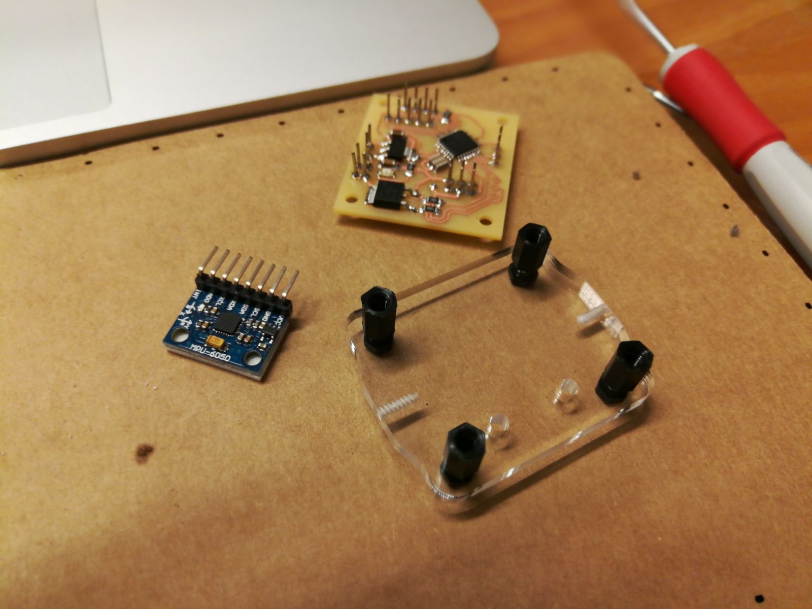
First i tested the serial connection using the Olimex HC-06 bluetooth module, connecting it with my mac and using the “screen” command to test the incoming data like i did on Networking Week -> LINK
After i tested the MOSFET to find the minimum PWM able to make the motors spin.