Objectives:
- Automate your machine
- Document the group project and your individual contribution Intro, The "Net" Explained, Master Code, Slave Code, Electrical Connections
Intro
During this week we had to automate the machine we designed during week 9.
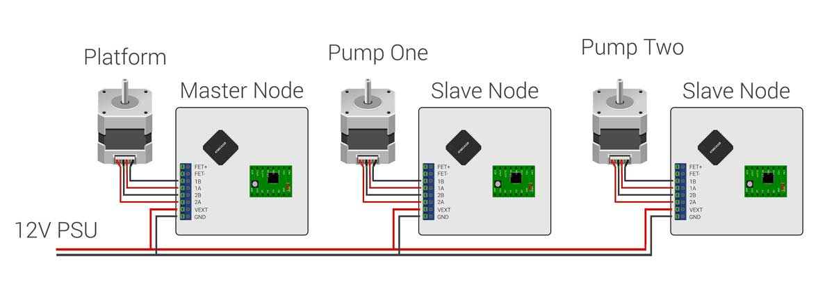
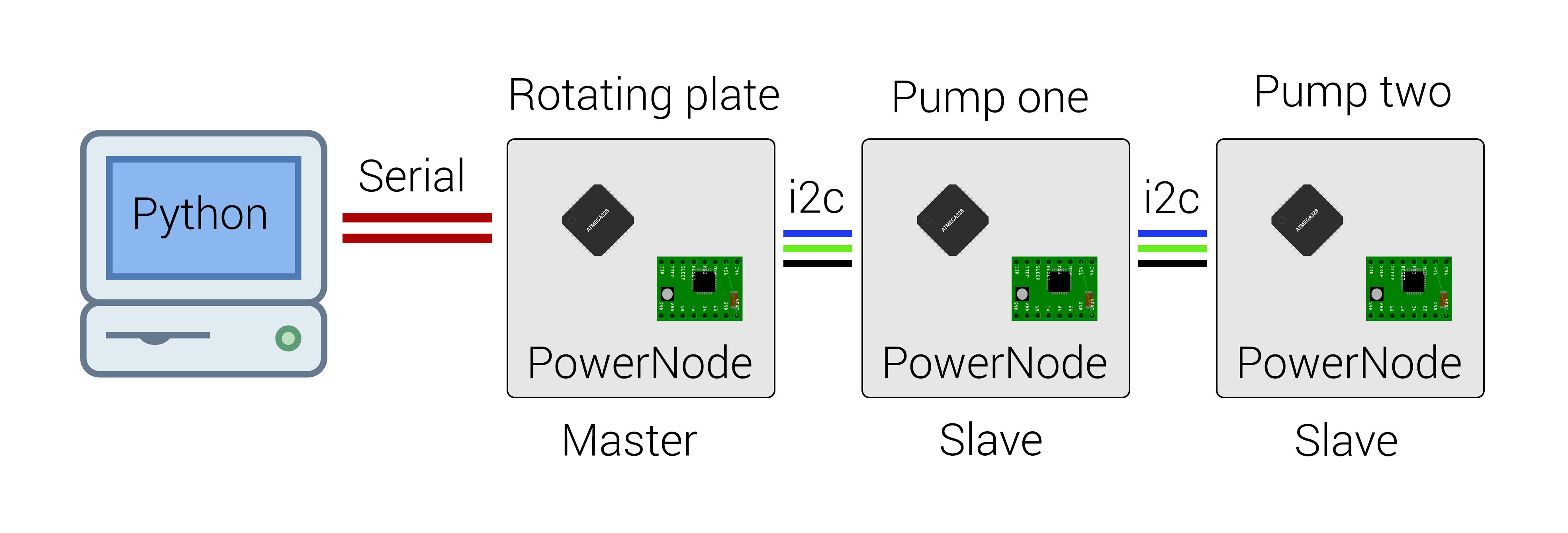
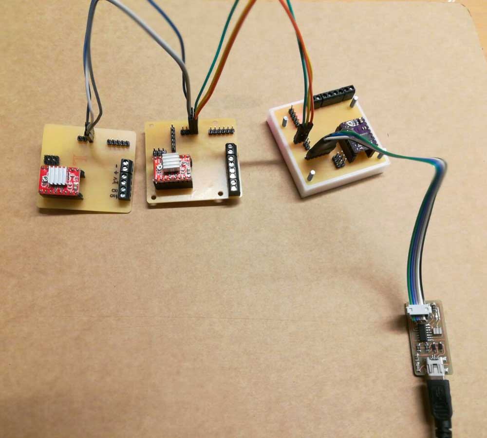
At week 10 ( Output Device ) i designed an input/output board aimed to control machines. The board have an integrated FTDI header and we will use it to communicate serially with the computer. We replicated the same board for each motor we use in our machine because the idea is to send command, via serial, from the computer then the first board/node ( Master ) handle the serial packet, parse it and route the information to the other boards all connected with i2c ( Slaves ).
Group Work Page HERE
GitHub Powernodes Page ( eagle file ) HERE
The "Net" Explained
The computer have a GUI written in python using PyQt4 which my project mate Simone coded from scratch. The GUI let the end user select the percentage of each liquid that will be poured into each test tube.
The machine can handle up to 18 test tubes and we did install two peristaltic pumps so we only have two fluids to chose from but, thanks to the scalable system of nodes we developed, is really easy to add more pumps.
The GUI sent through serial port a packet containing the test tube number, the percentage of the first liquid and the percentage of the second liquid. The first board/node parse the serial package and move the rotating platform to the desired test tube. Next the Master send an i2c request to the pump number one which pour the requested quantity and send back an ACK to the Master; same thing for the second pump. After The test tube is filled with the required combination of liquids the Master send via serial port a symbol acknowledge the python gui about the successful operation. And so on with each tube.
Master Node Code
Here’s the code for the master node, you can find the libraries i wrote for the machine in my github repo. Link
#include < Wire.h >
#include "Platform.h"

#define DRIVER_ENABLE 5
#define DRIVER_STEP 6
#define DRIVER_DIR 7
#define LED 2
#define SERVO_1 9
#define SERVO_2 10
#define THERMISTOR A1

#define MAX_TUBES 18
#define STEPS_PER_TUBE 30

Platform platform(DRIVER_ENABLE,DRIVER_STEP,DRIVER_DIR, MAX_TUBES, STEPS_PER_TUBE);

int tube_number = 0;
int pump_one = 0;
int pump_two;

void setup() {
  Serial.begin(9600);
  Wire.begin();
}

void loop() {
  while (Serial.available() > 0) {
    int tube_number = Serial.parseInt();
    int pump_one = Serial.parseInt();
    int pump_two = Serial.parseInt();
    if (Serial.read() == '\n') {
        platform.goTo(tube_number);
        blink_led(1);
        delay(500);
        Wire.beginTransmission(10);  // transmit to pump number 1
        Wire.write(pump_one);       // send the % to flow
        Wire.endTransmission();     // stop transmitting
        blink_led(2);
        delay(500);
        Wire.beginTransmission(20);  // transmit to pump number 2
        Wire.write(pump_two);       // send the % to flow
        Wire.endTransmission();     // stop transmitting
        blink_led(2);
        delay(500);
        Serial.println(1);          // send the ACK back to the computer
    }
  }
}

void blink_led(int numb) {
  for (int i=0; i < numb ; i++)
  {
      digitalWrite(LED, HIGH);
      delay(200);
      digitalWrite(LED, LOW);
      delay(200);
  }
}
Slave Nodes Code
#include
#include "Pump.h"

#define DRIVER_ENABLE 5
#define DRIVER_STEP 6
#define DRIVER_DIR 7
#define LED 2
#define SERVO_1 9
#define SERVO_2 10
#define THERMISTOR A1

Pump pump(DRIVER_ENABLE,DRIVER_STEP,DRIVER_DIR);

void setup() {
  Wire.begin(8);                // join i2c bus with address #8
  Wire.onReceive(data_from_master);
  Wire.onRequest(data_to_master);
}

void loop() {
  delay(100);
}

void data_from_master(int num_bytes) {
  pump.flow(200);
  Serial.println("bella");
}

void data_to_master () {
  Wire.write(1);
}
Electrical Connections
All the nodes are powered by a 12V power supply. The node has in internal 5V voltage regulator to power the ATmega328p.