Objectives:
- Design and build all the mechanical part of the robot. Sphere Shell, Spare Mechanical Parts, Downloads
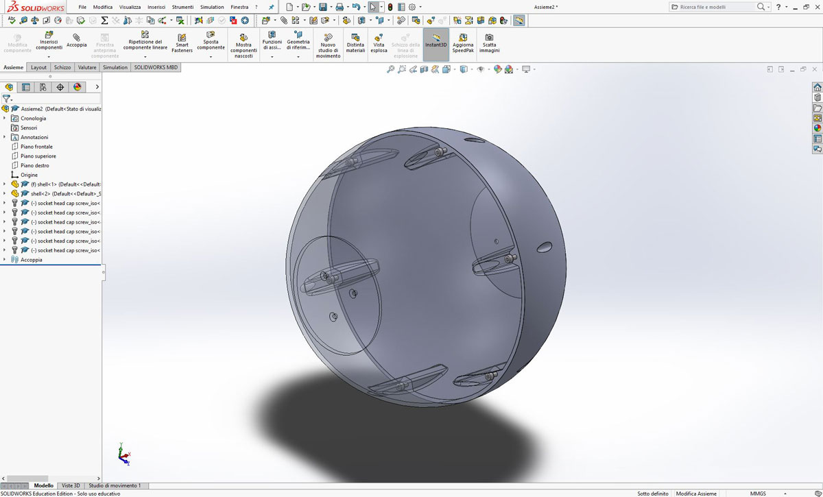
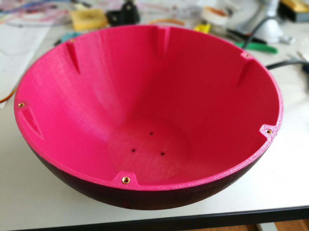
The Shell
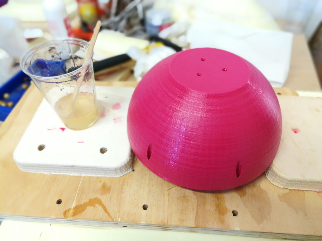
My personal goal was to build the robot as small as possible but to keep the price down and use as much as possible hardware we already have in the lab ( fablabs inventory ) i had to rethink about the dimensions. On the other hand i was limited in size by the 3D printer bed size so i designed the sphere having 200mm diameter which perfectly fit the Ultimaker 2 bed.
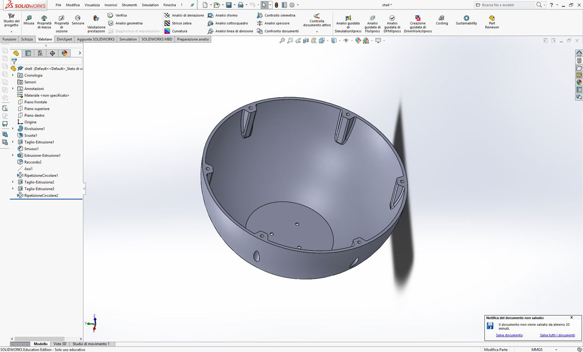
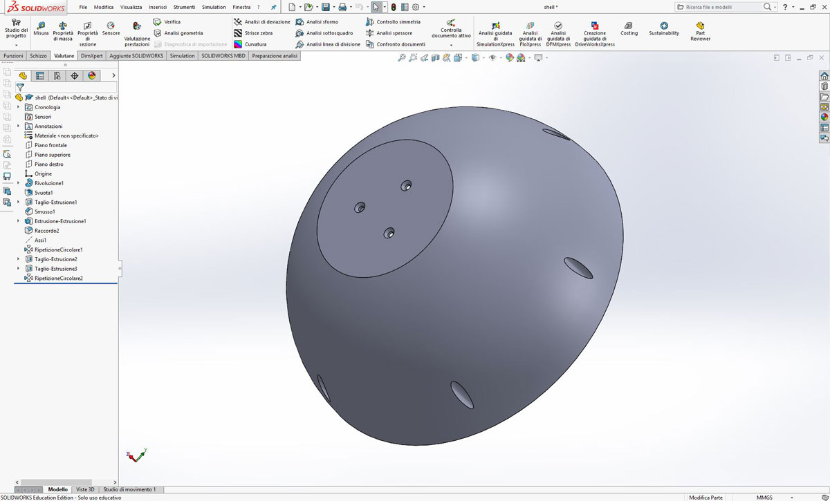
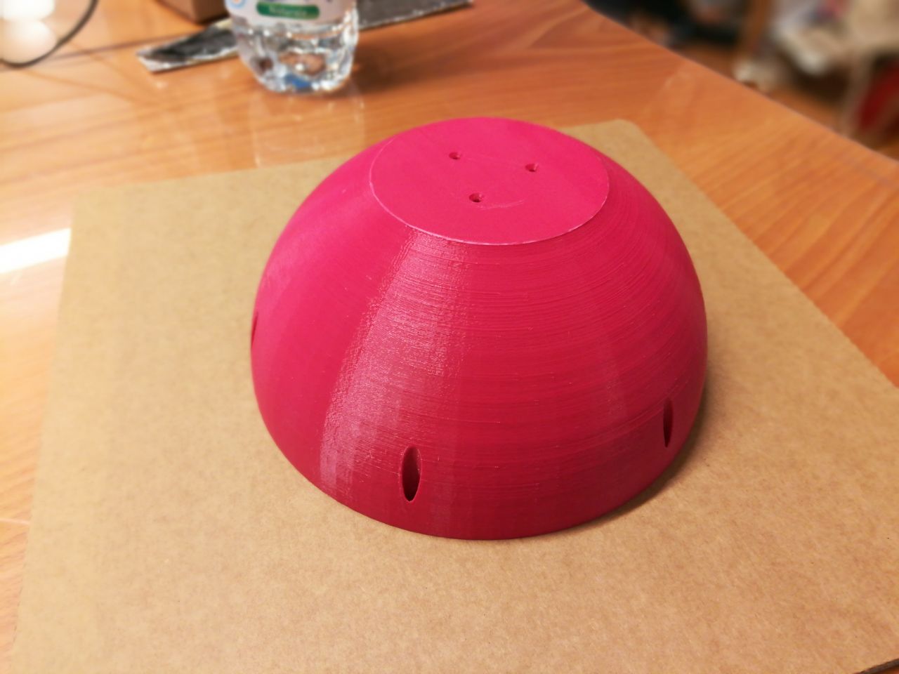
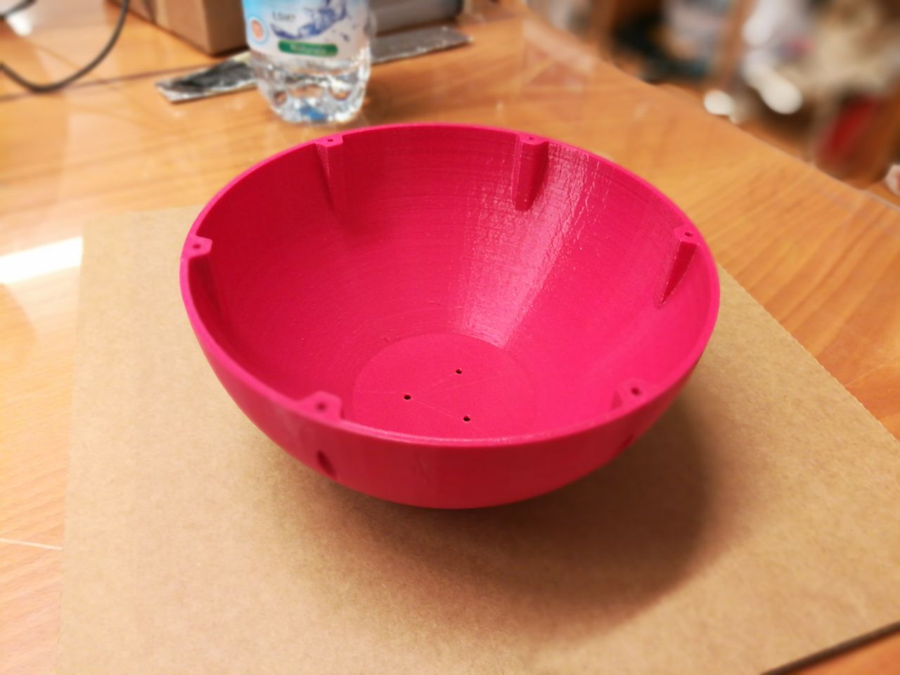
The robot is composed by two half sphere kept together with six screws.
The magenta filament i used is branded 3D Prima and it’s PLA.
I printed the other half sphere with a custom built delta we have in our lab and the filament i used is from an italian company MAKE SHAPE , PLA 1.75mm diameter.
The settings i used are:
- Layer height: 0.25mm
- Infill: 20%
- Print Temperature: 215° C
- HeatBed Temperature: 60° C
After i sanded the ball and i coated it with epoxy resin to give additional strenght.
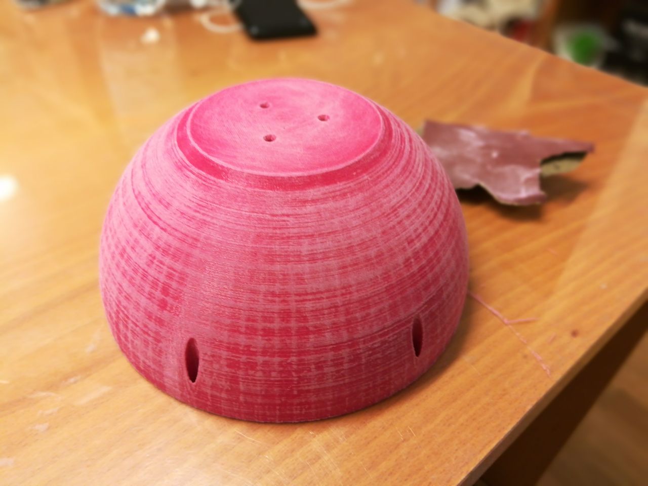
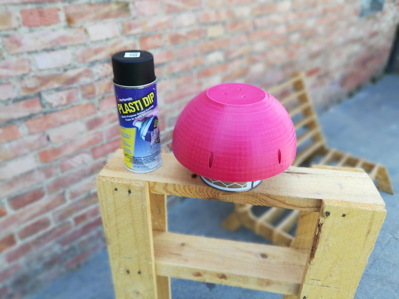
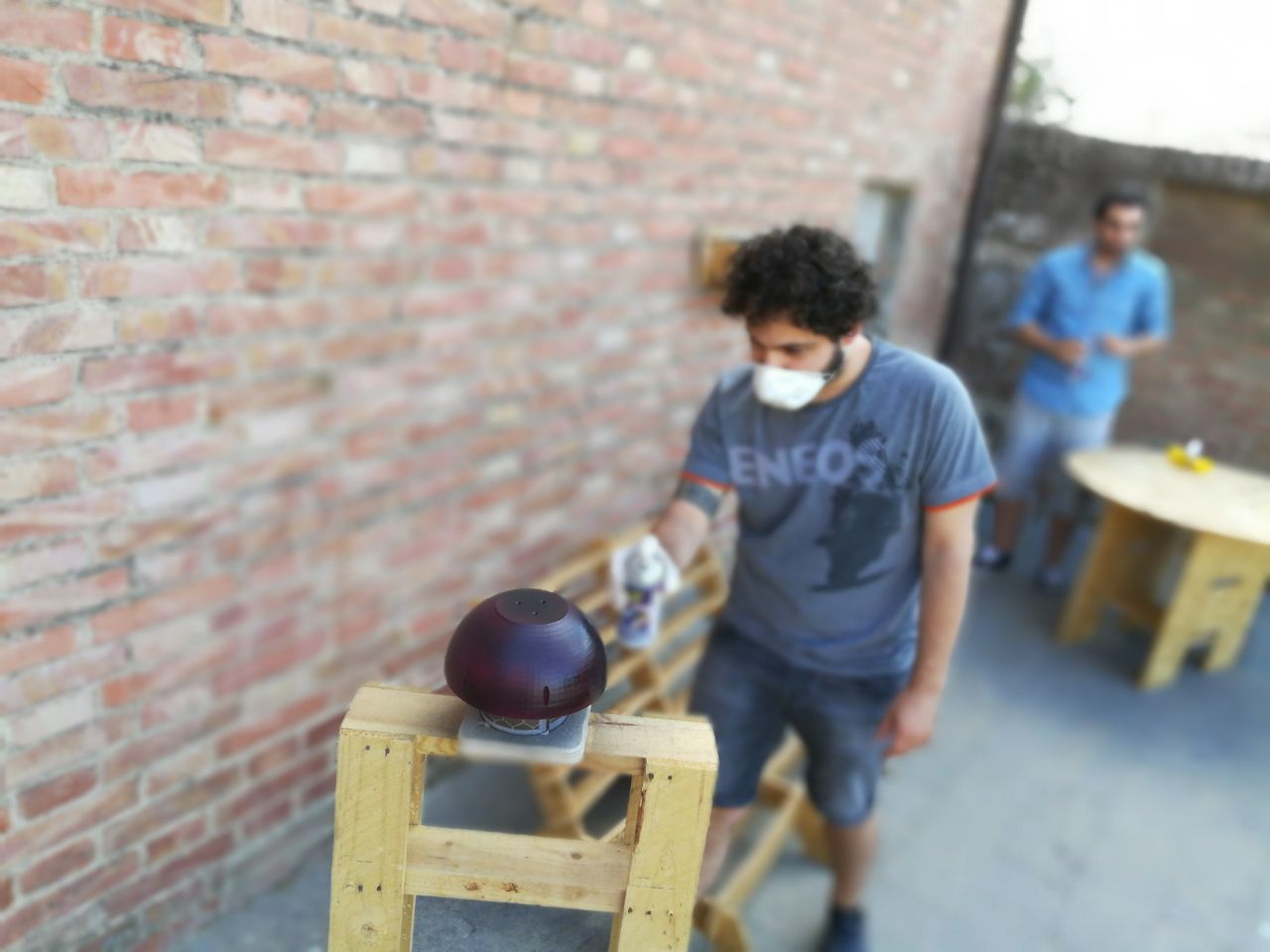
To give some “grip” to the shell i used a special rubber spray called Plasti Dip --> Plasti Dip Website
The last step was to melt inside the plastic M3 threaded inserts. To do so i used the tip of the soldering iron, heated at 160°C, to push the threaded insert inside the plastic holes.
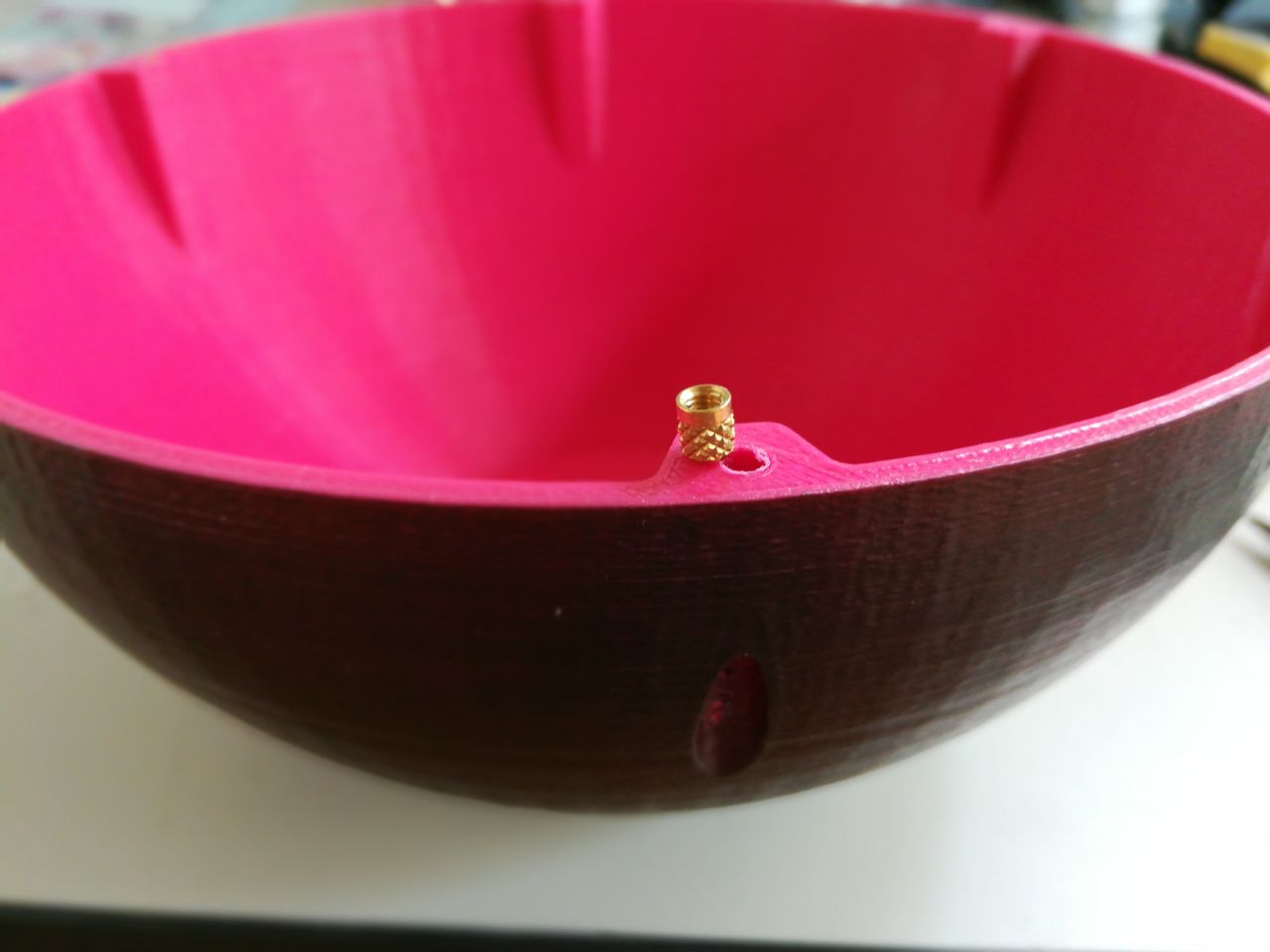
I repeated the same process for the other half of the shell.
Spare mechanical parts
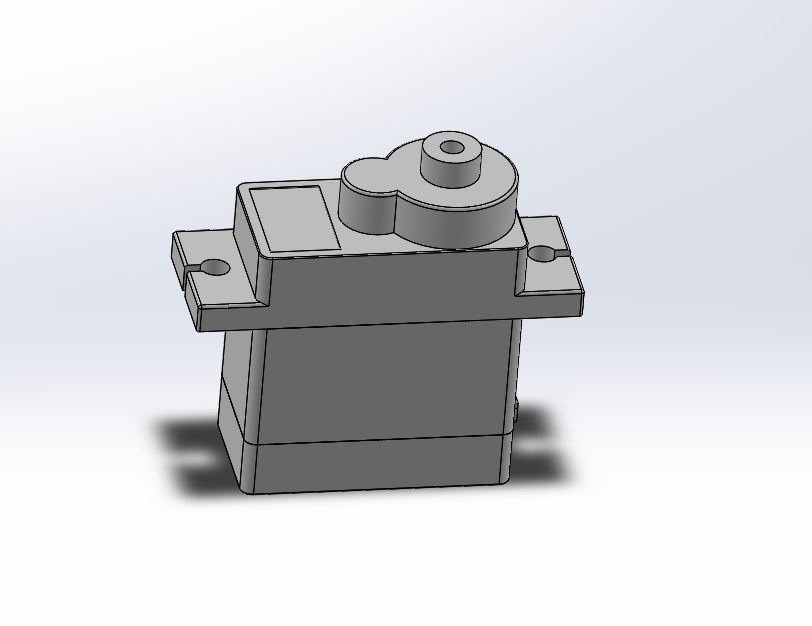
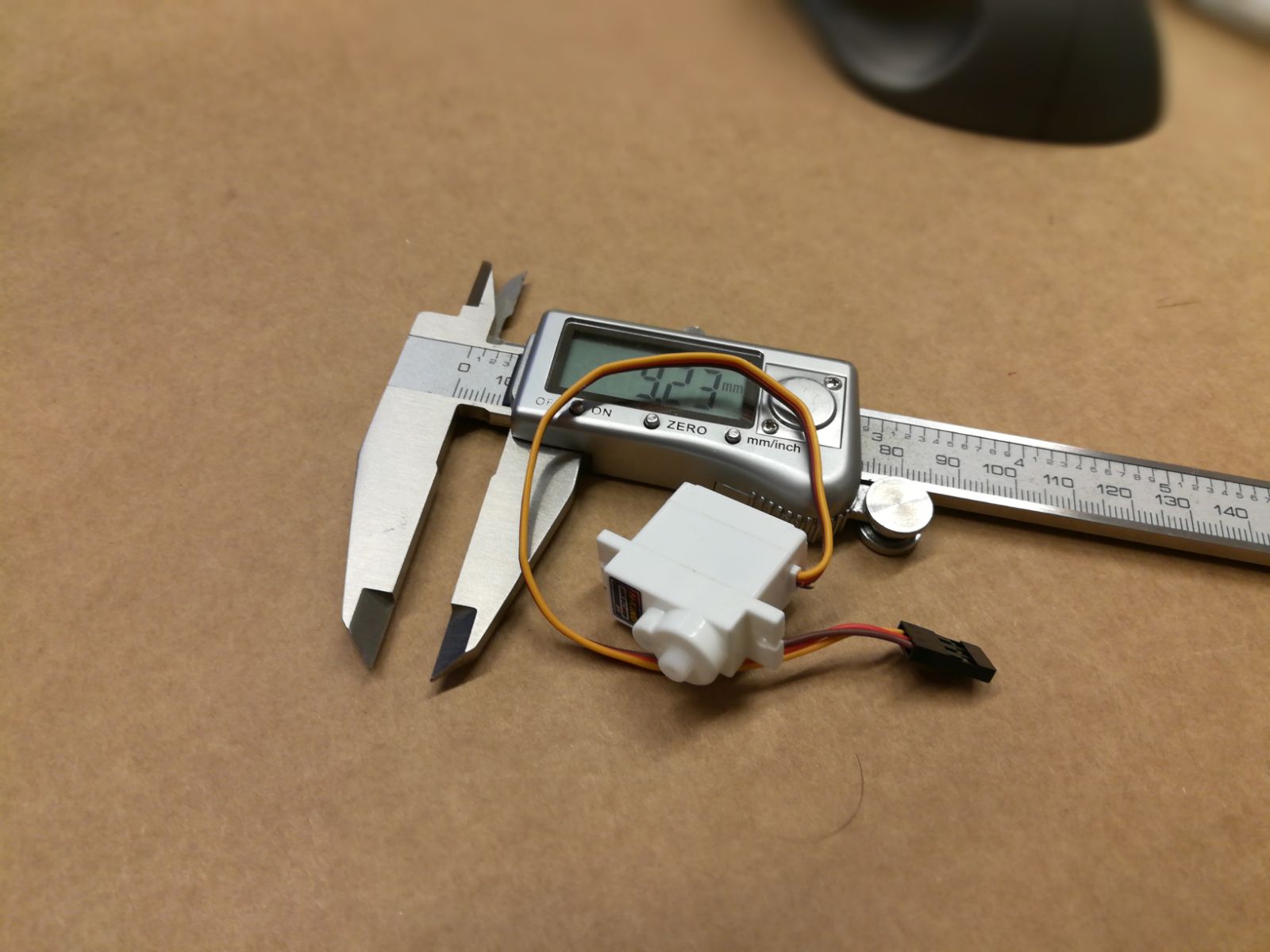
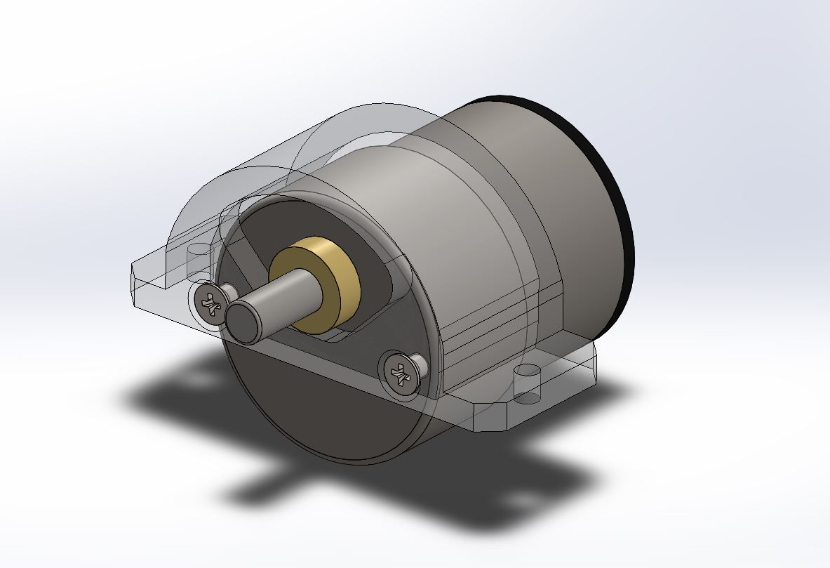
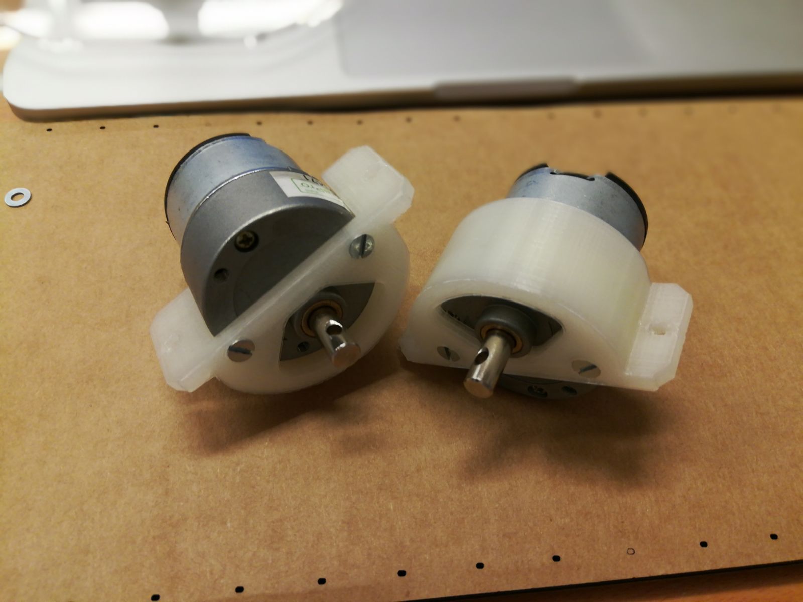
The first step was to design all the commercial parts i used like the Servo motor and the DC motors.
Servo motors are Hobby King HK SCM9.
Product Page
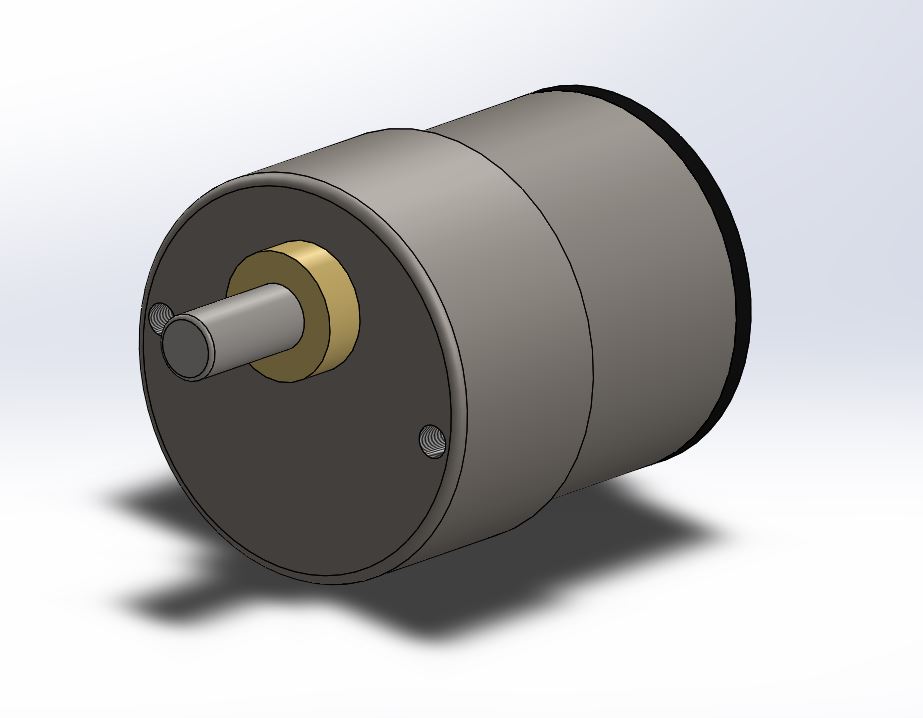
And the DC motors are Jameco 253471 Product Page
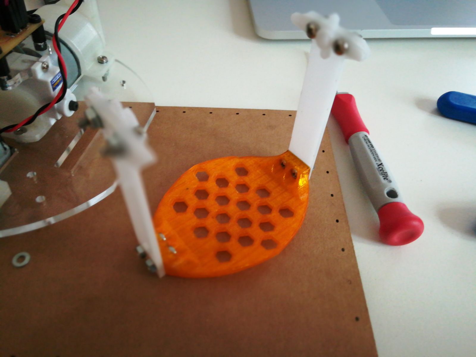
After i designed the pendulum plate that will hold the battery back below the main platform.
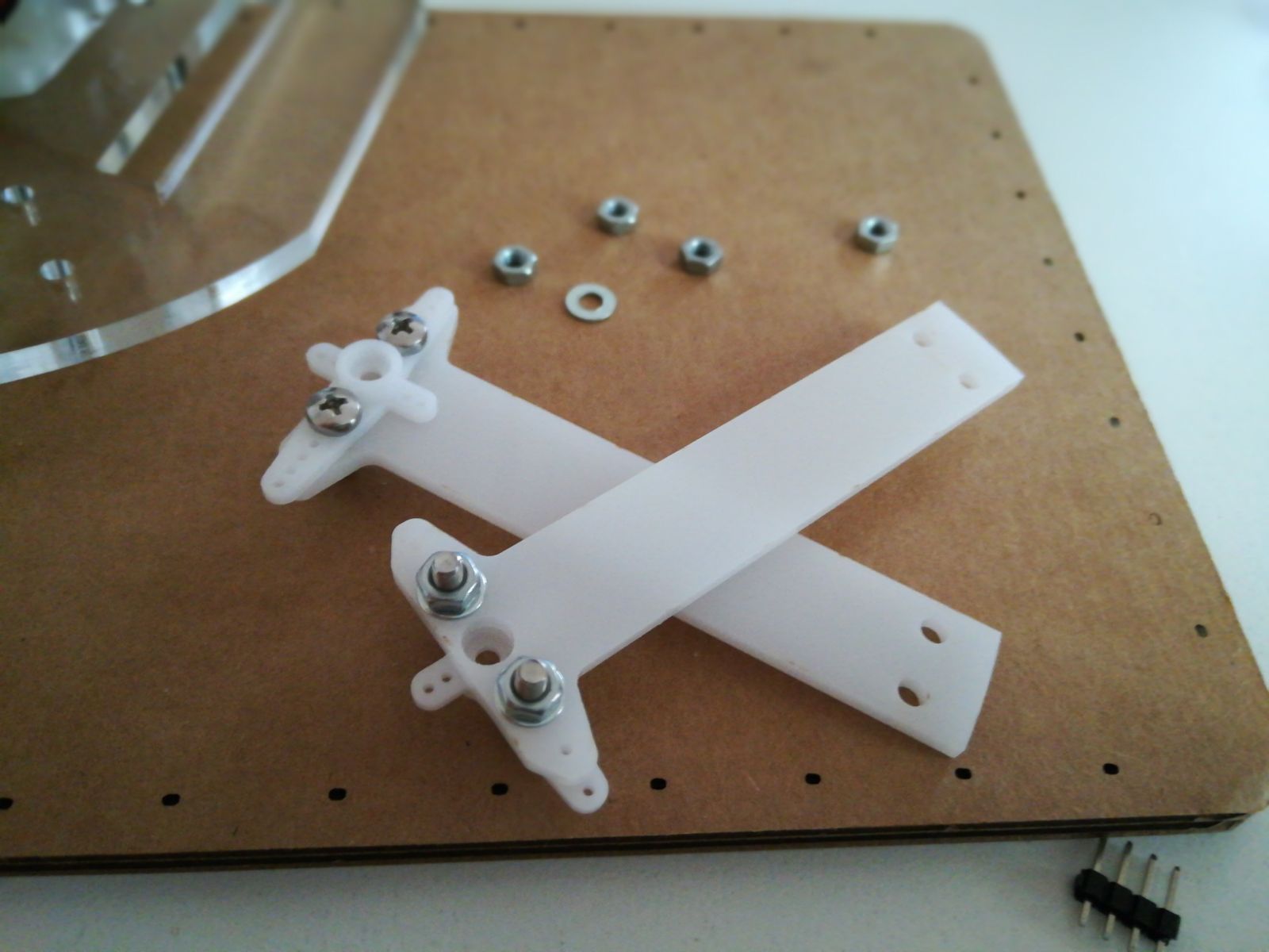
The plate is connected to the servo with two acrylic pieces i cutted using the laser cutter.
At the beginning i tried to glue the acrylic to the servo arms using super glue but just using a small pressure the bond broke so i decided to put 2 screws to hold everything.
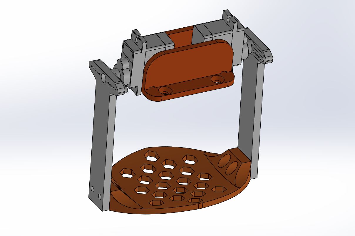
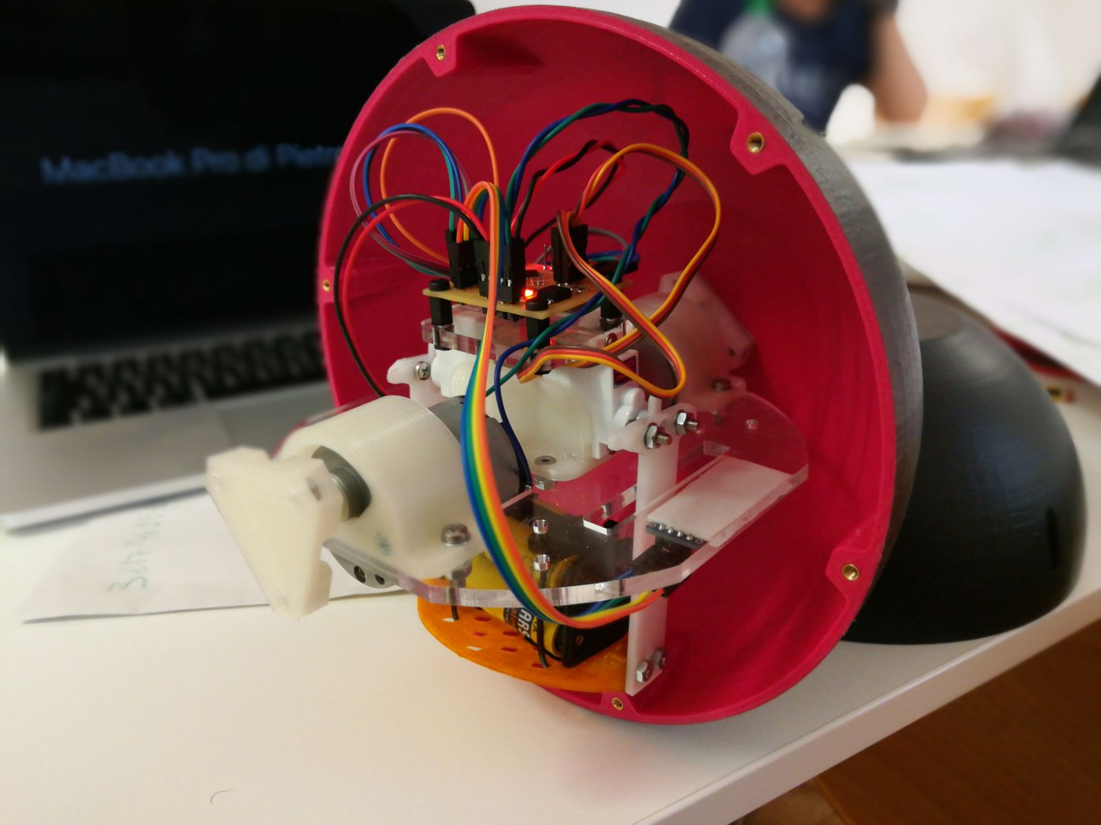
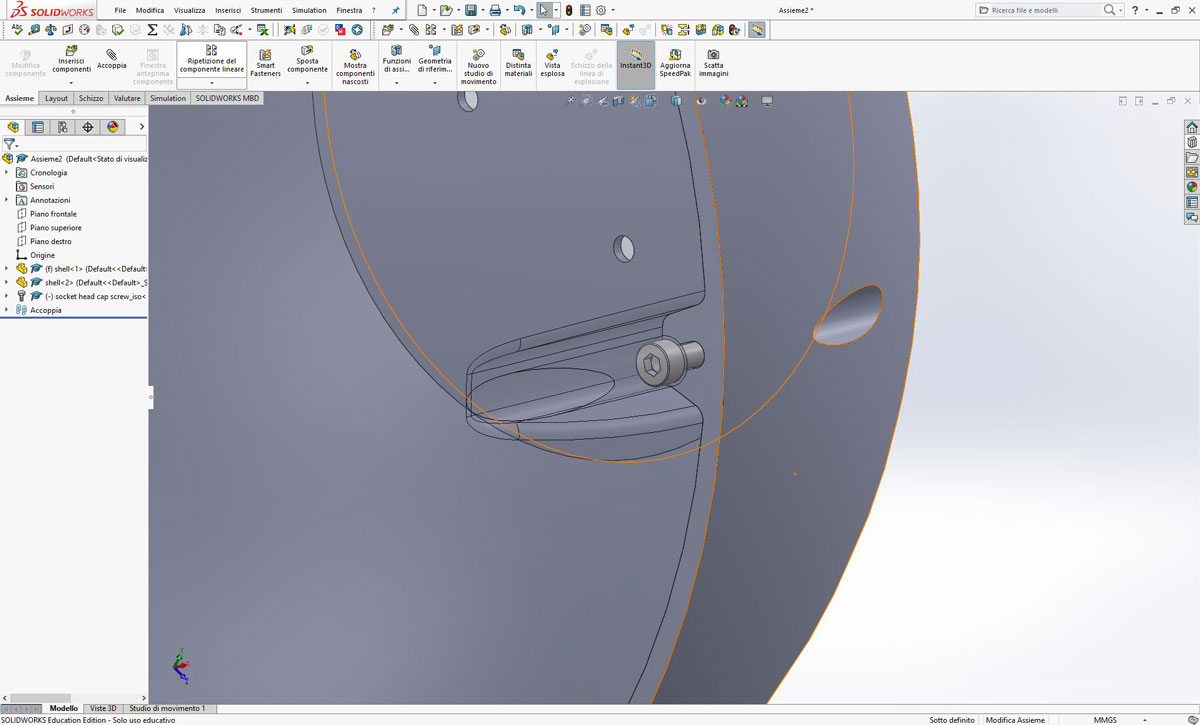
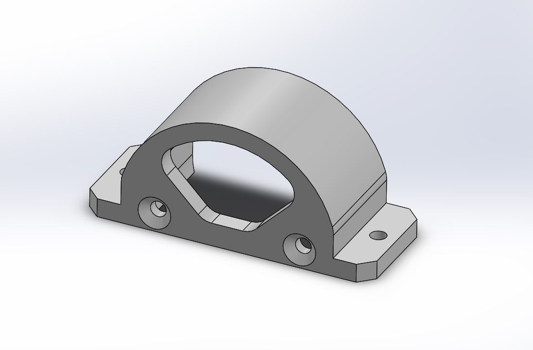
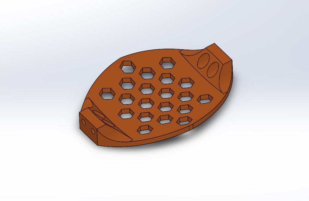
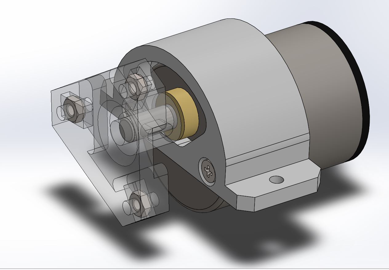
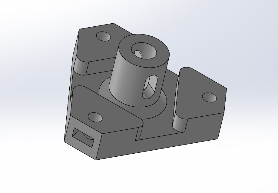
The last part i designed is the piece that connect the motor shaft to the outer shell of the robot. The part have three pockets that hold an hex bolt so i can screw from outside the shell to the part.
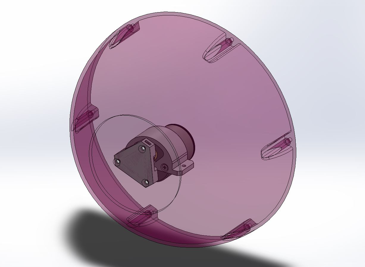
Below all the parts assembled. ( messy cables : [ )