Objectives:
-
Measure something, add a sensor to a microcontroller board that you have designed and read it.
Intro, Theory, Wheatstone bridge, Op-Amp, The board, Downloads
Intro
This week i decided to give a look at resistance temperature detectors (RTDs) which are sensors used to measure temperature. The main advantages over thermocouples are higher accuracy and repeatability. The sensor i'm going to use is a standard PT100 that measure 100 ohm at 0° C, the more the temperature increase the more the resistance increase.
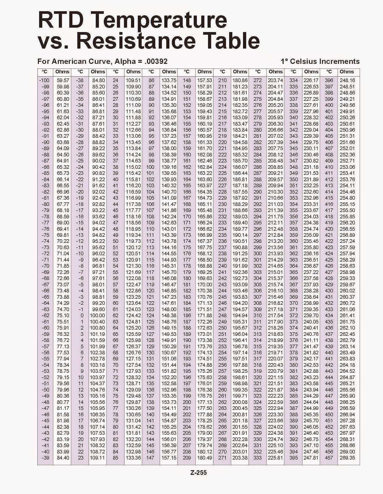
The resistance value can be converted to degree using the following linear formula:
Rt = Ro*(1+alpha*T)Where:
- Rt = is the resistance at the temperature t [ ohm ]
- Ro = resistance at the temperature 0° ( 100 ohm for PT100 ) [ ohm ]
- alpha = is a constant 0,00375 up to 0,003928 ( depends on the sensor ) [ ohm / ohm / C° ]
- T = temperature [ C° ]
Reading the analog signal with a microcontroller
The Atmega328p ADC have a 10 bits resolution that mean, given 5V voltage reference, an accuracy of 4.88 mV ( 5000 mV / 1023 ).
If we read the PT100 using a voltage divider with another 100 ohm resistor the output voltage at 0° will be 2,5V and the output at 400° ( 249,56 ohm ) will be around 3.5 V so in the range [ 0 - 400 ] C° the voltage span is 1000 mV.
This way we use only 20% of the ADC scale and the resolution we can read is really poor: 400 / ( 1023 / 5 ) = 2 C° .
To increase the resolution we have to create a conditioning circuit.
The optimal scenario is to have an output of 0V at 0° C and 5V at 400° C meaning 400 / 1023 = 0,39° C accuracy; way better than the 2°C we had before.
The first step is to convert resistance change into a voltage change. We have to options:
- Voltage divider: the advantage of a voltage divider over the wheatstone bridge is the simplicity of the build. It has a pull-up resistor which can be chosen to minimize the current going to the ADC input. On the other hand it’s very sensitive to thermal change and doesn’t have any error cancellation.
- Wheatstone bridge: is simply two voltage divider, the first is composed by R1 and R3 and the second one by R2 and R4 where R3 is the PT100 sensor. The voltage is measured from the middle point of the two voltage divider. The 3 resistors are sized so that the voltage at the min temperature give a voltage output of 0V, increasing with the increase if the temperature. As you can guess the wheatstone bridge is way more accurate and you can play with the resistors to eliminate the errors.
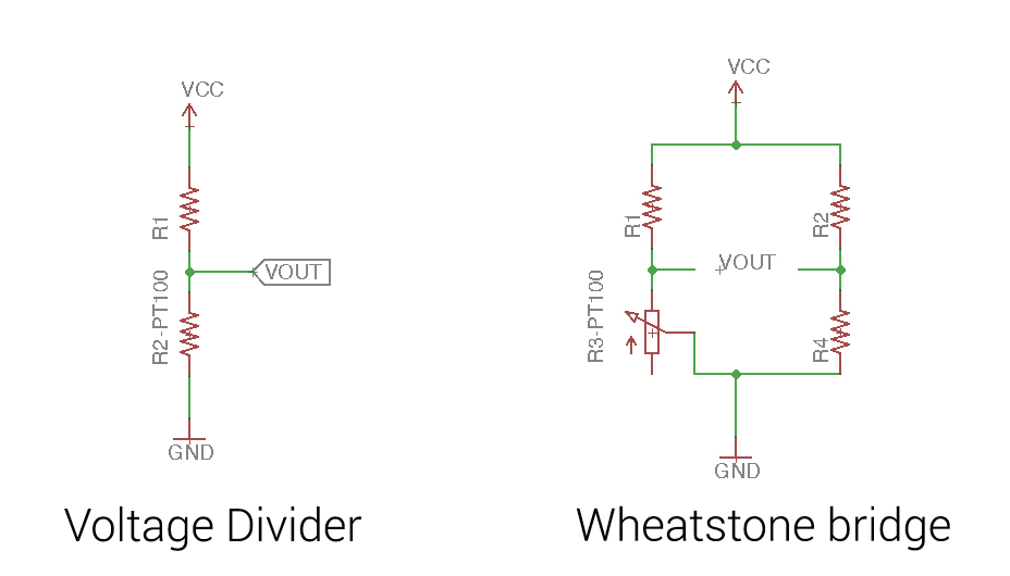 For this sensor i’ll use a wheatstone bridge.
Wheatstone bridge
To balance the bridge at 0° C R4 have to be 100 ohm and i calculated R1 = R2 so that the max current flowing to the sensor is < 3mA.
I = Voltage Ref / ( R1 + Rt ) worst case when Rt is at the min temp ( 0°C -> 100 ohm ).
I = 5v / ( R1 + 100 ) => 1566 ohm very close to the standard 1.49k ohm.
So R1 = R2 = 1.49k ohm.
To check if everything was working as expected i simulated the circuit with National Instruments Multisim. I emulated the PT100 using a 300 ohm potentiometer, when the pot is at 33% ( 100 ohm ) i get a voltage output of 5mV ( close enough to 0 ) and when the pot is at 100% ( 300 ohm ) i get 528mV.
NOTE: 300 ohm = 500°C more than i need.

Fitting the 0-5v range ( op-amp )
Now i’ve got my voltage starting from 0 and going up to 500mV around 450 degree. I need to amplify this range to fit the full 328p ADC scale of 0-5 V. The gain i need to have is around 10x.
Since the signal i have is measured across the two bridge outputs and not from a terminal to ground i can't use a normal non inverting op-amp but i have to use a differential op-amp.

If R1 = R2 and Rf = Rg the differential op-amp gain can be calculated with the following formula:
Vout = Rf / R1 * ( V2 - V1 )
So to have a gain of 10x i chose Rf and Rg to be 10k ohm and R1 and R2 1k ohm.
Next i simulated the circuit using the rail-to-rail AD8605 op-amp, we have in the FabLabs inventory list, and the resistors calculated above.
AD8605 Datasheet
As you can see the range now goes from 50mV to 4.73V.
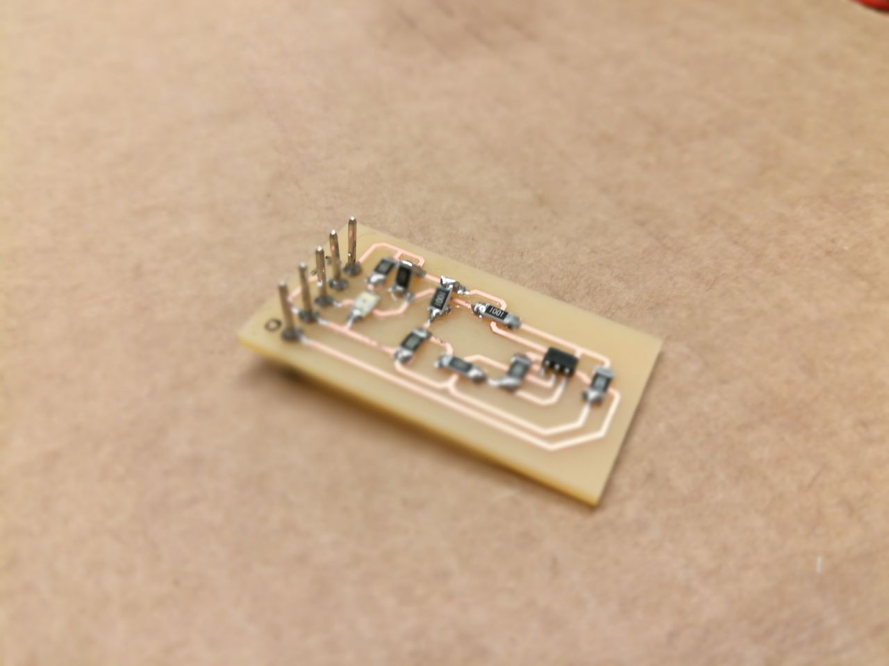
The Board
I used eagle to create the schematic and route the traces. I added a power led.
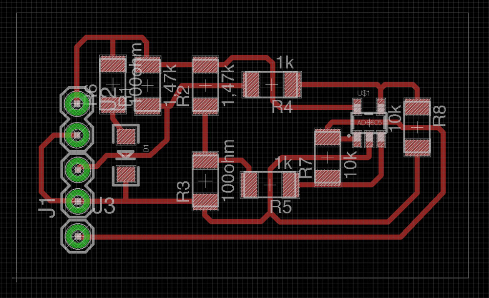
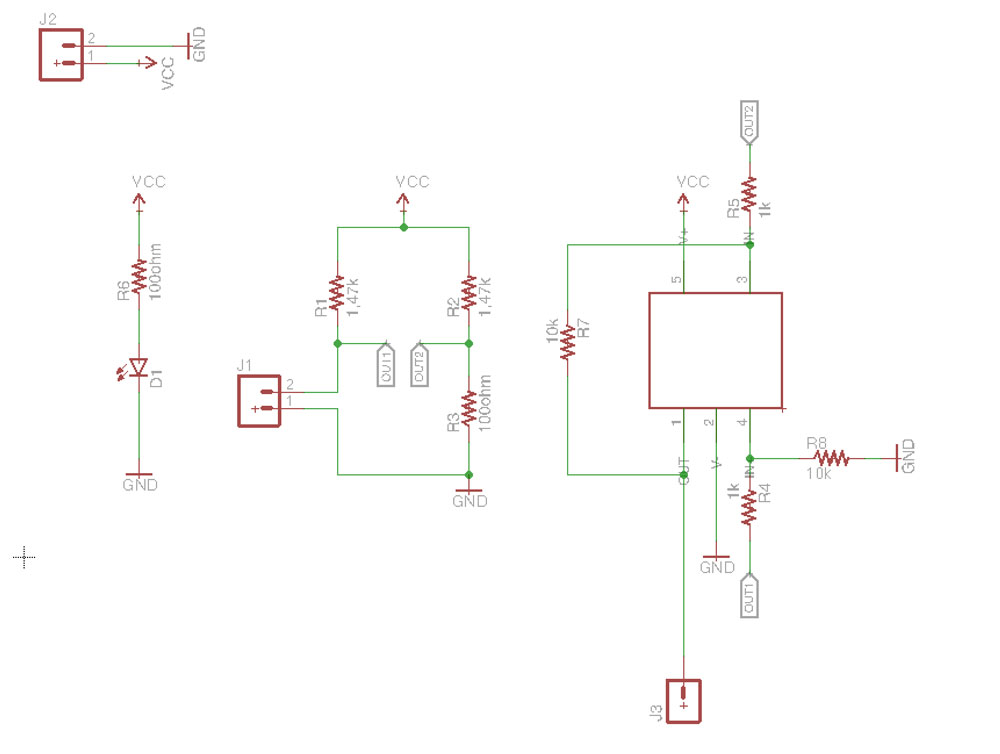
I milled the board using a Roland SRM-20; 1/64 end mill to isolate the traces and 1/32 end mill to cut the holes and the outline.
After i soldered the board, it was very challenging because i had to use the ancient method of the “series pyramid resistors”. :D ( in our lab we dont have the 1.47k ohm resistors so i used 1k + 500 ohm. )
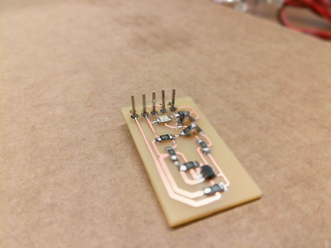
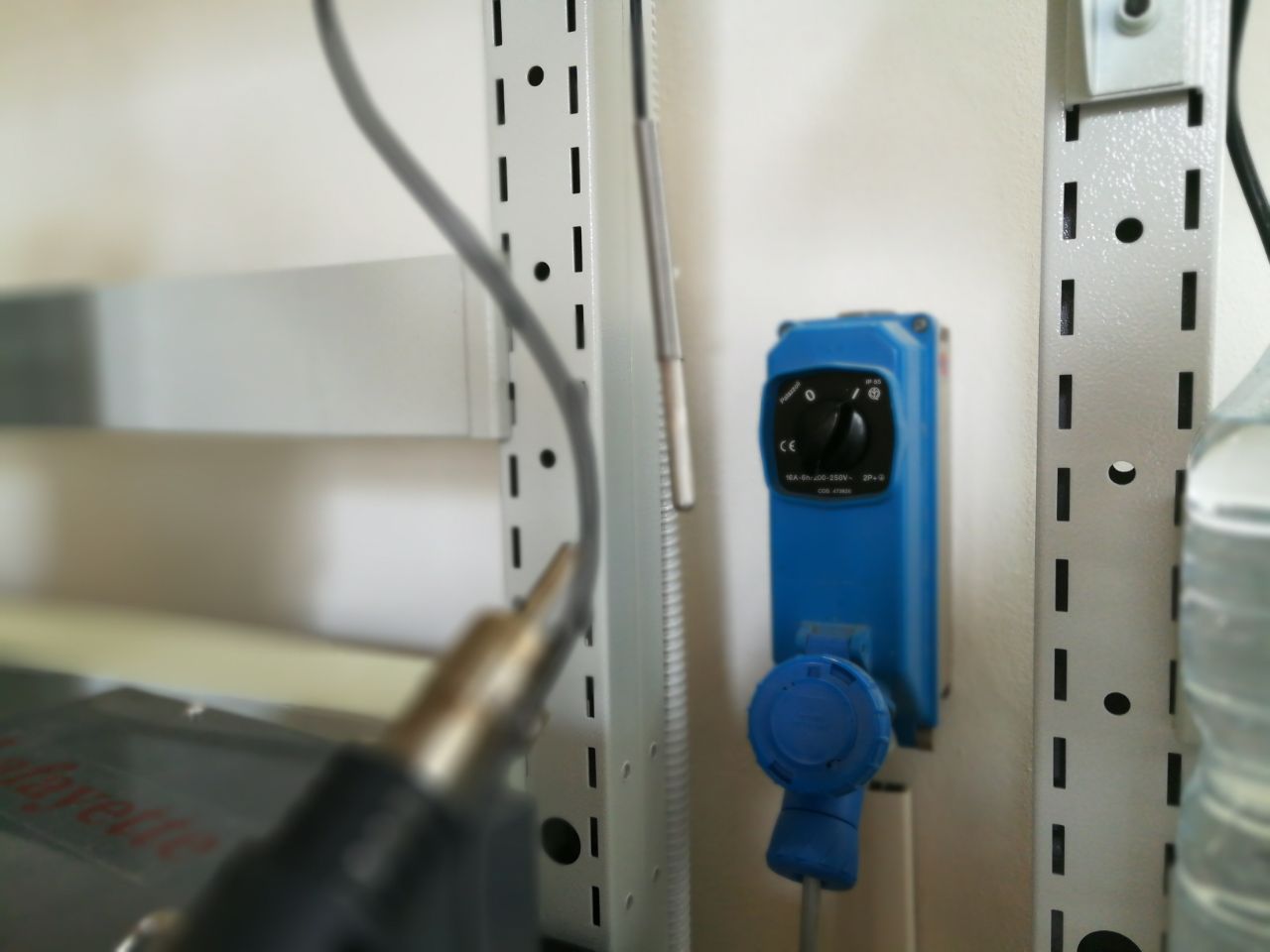
Next i powered the board using a stabilized power supply, setted at 5.00V i connected the PT100 sensor and measured the voltage output using the voltmeter.
The output at 23° C ( ambient temp ) was around 70mV and using an air gun i heated the sensor around 200° C reading an output of 2.3V. The board looks like it’s working but to use it with a microcontroller it have to be calibrated using fixed temps like a container with melting ice for the 0°C and boiling water for the 100°C.