Objectives:
-
Design and build a wired &/or wireless network connecting at least two processors
Intro, Board, Handle, Testing
Intro
This week we had to make two processors communicate and i took the opportunity to create something for my final project.
Since i have to control my robot wirelessly i decided to build a wireless joystick which send the data via bluetooth to the robot.
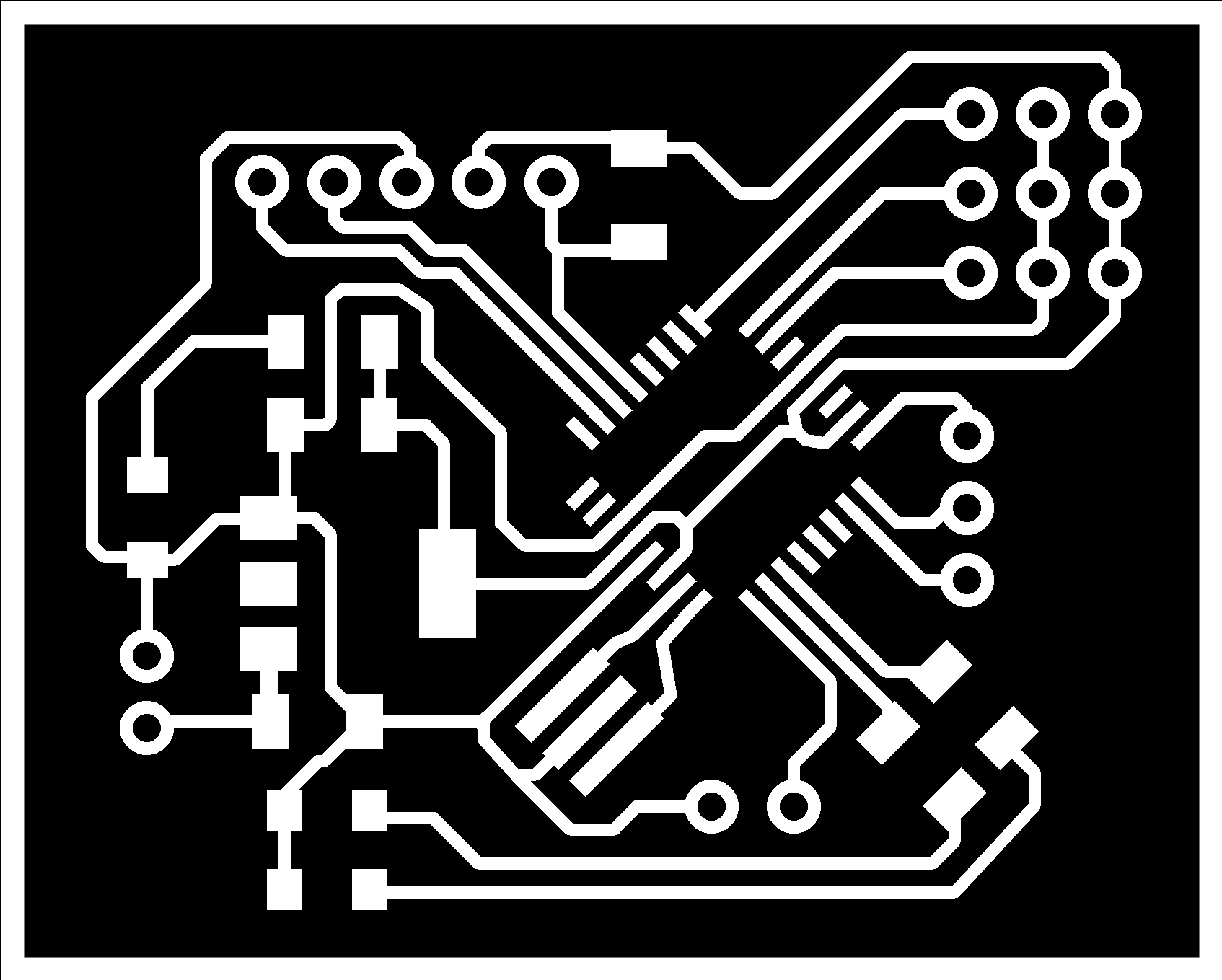
Board
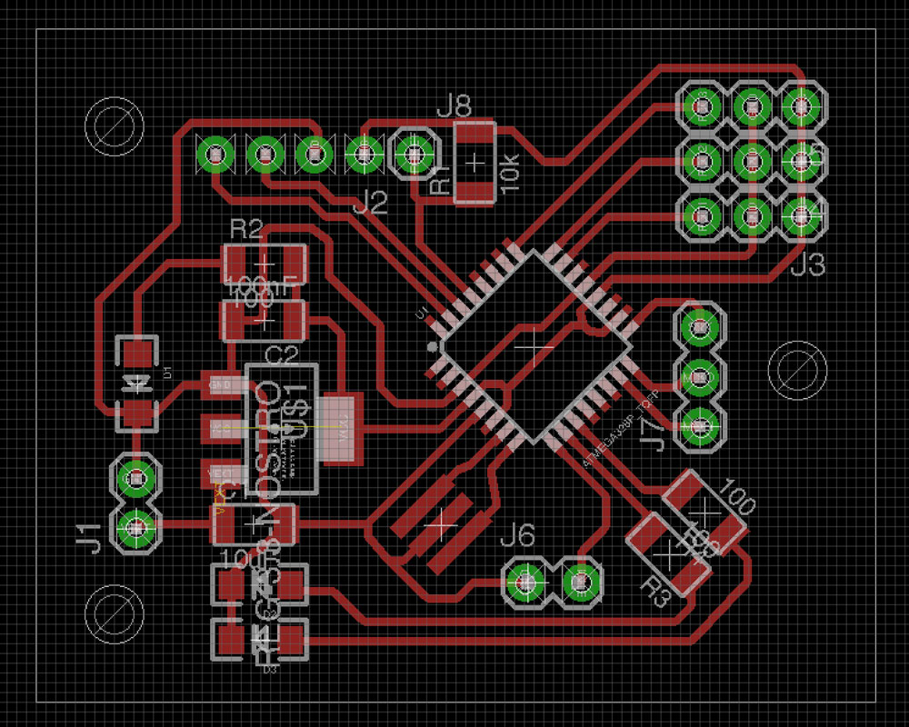
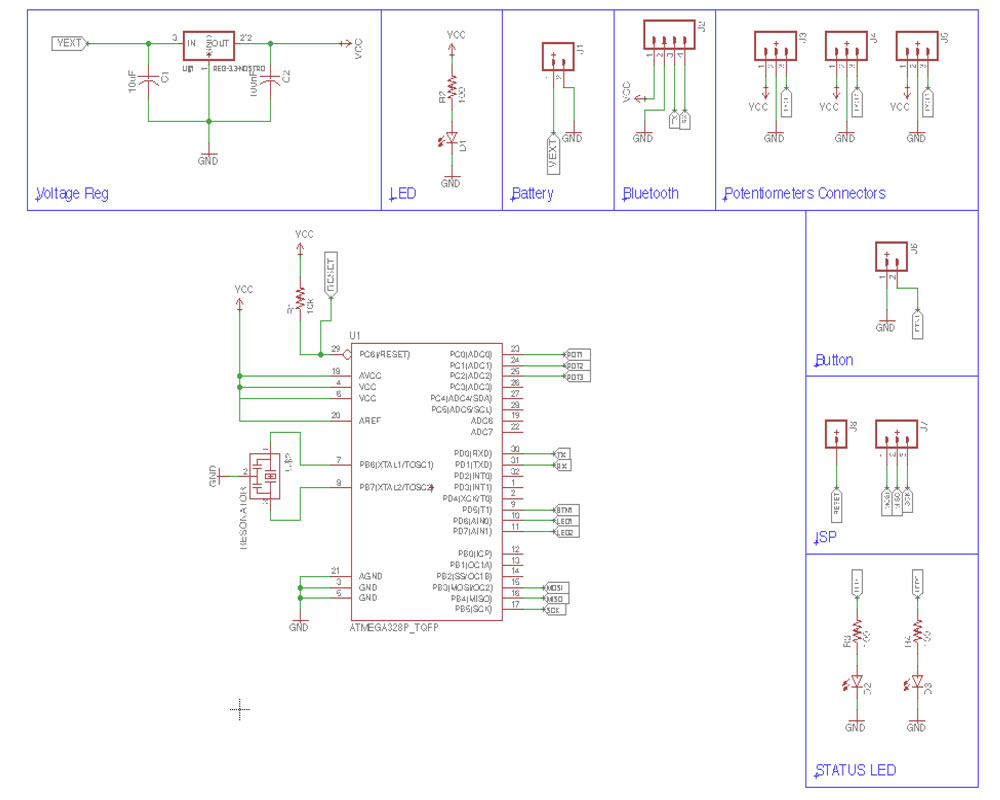
I designed a board able to read three potentiometers, one push button, two status LED and an the RX/TX pins exposed to connect the bluetooth module.
The microprocessor is an ATmega 328p and the voltage get regulated with a voltage regulator circuit.
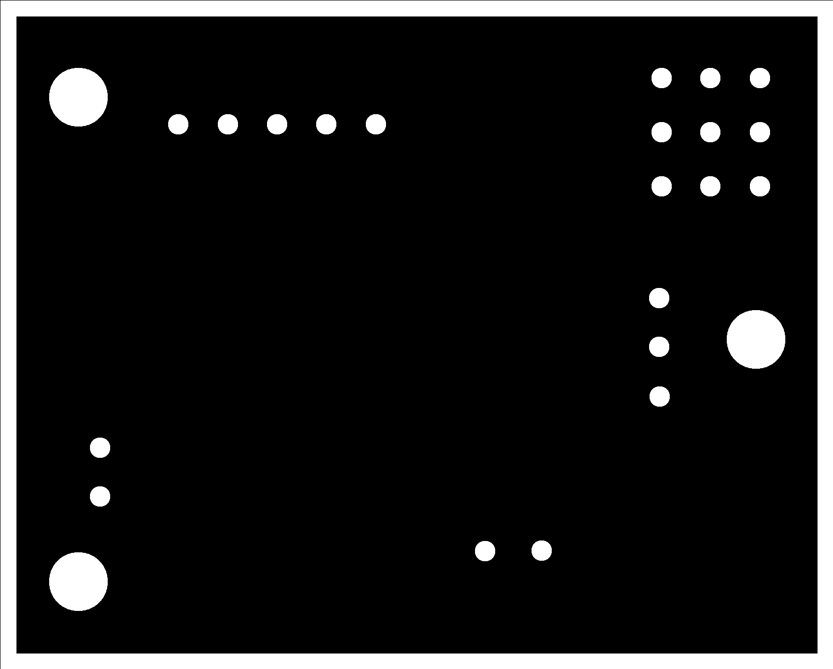
The board was designed with eagle and milled using 1/64” and 1/32” endmill on a Roland SRM-20.
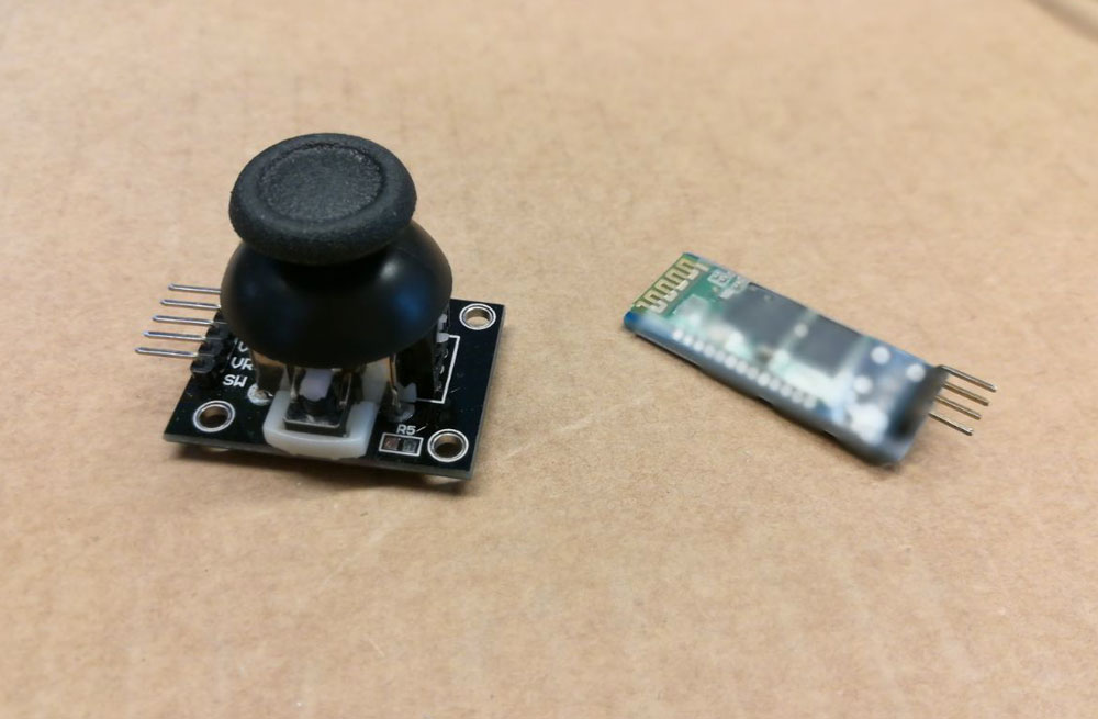
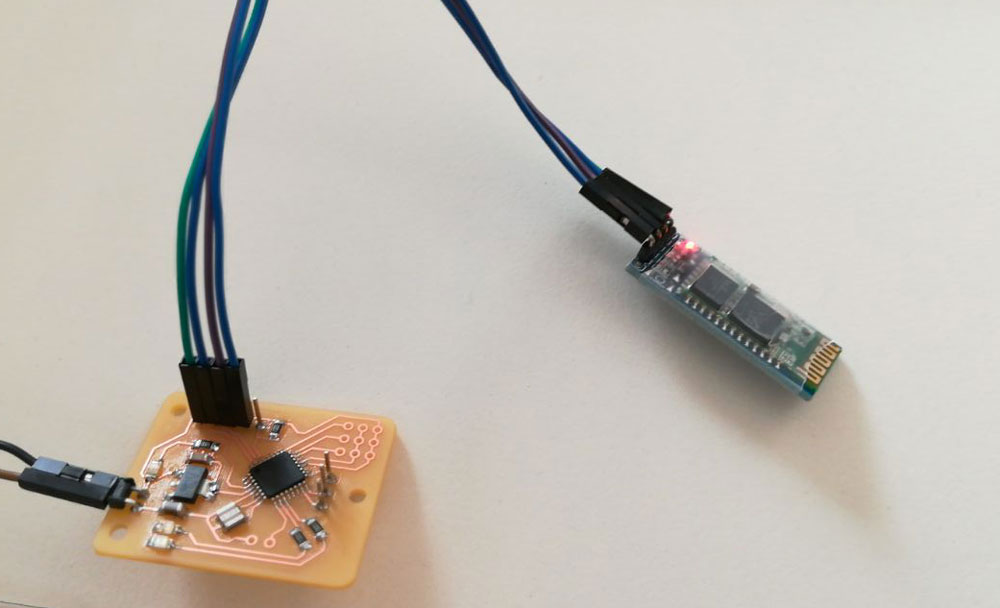
The bluetooth module is an HC-06 and i’m using an xbox joystick which has two potentiometer and an integrated push button.
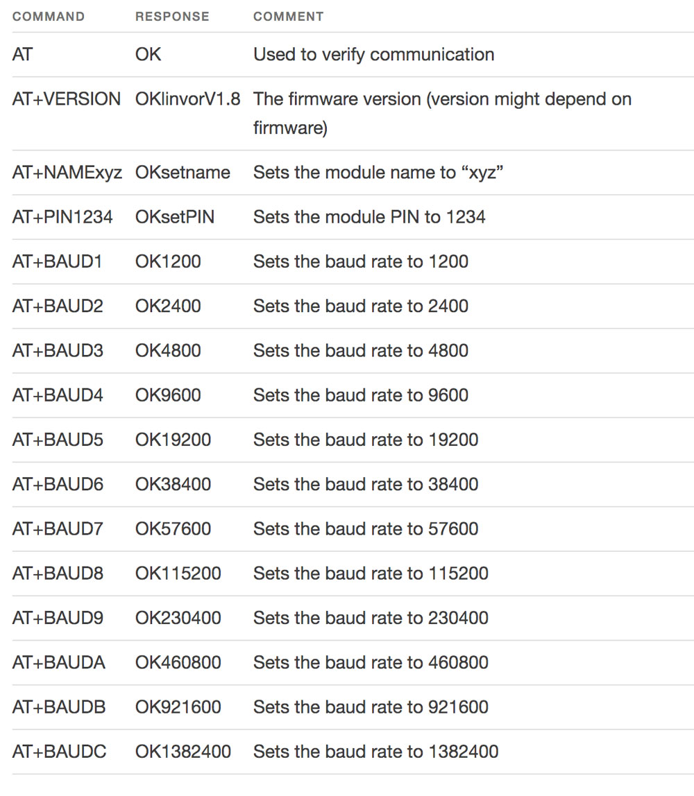
Before starting to write the software for the joystick i had to configure the HC-06 bluetooth module. in order to do so i connected the VCC and GND pin of the module to the Arduino’s one and the module Tx to Arduino Rx and module Rx to Arduino Tx.

Next i opened the Arduino IDE console and checked the bluetooth response by writing the AT command.
NOTE: you have to select No line ending in the list form of the console otherwise the bluetooth will not understand the command.
I set the bluetooth baudrate to 9600, pin to 0000 and name to SphereRobot.
After i wrote a simple code which read the status of the three analog inputs and the push button and send them via bluetooth separated by a semicolon.
I paired the HC-06 with my laptop and opened the serial monitor using the command:
screen /dev/tty.SphereJoystick-DevB 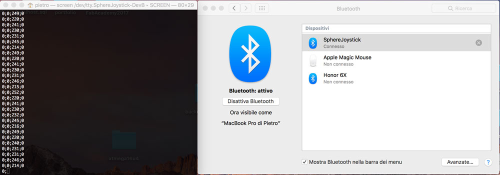
Since the analogs are unconnected i get random reads but that way i tested the comunication.
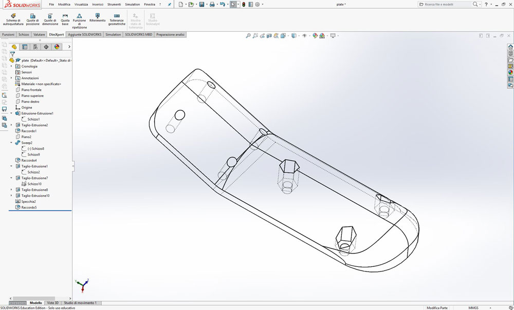
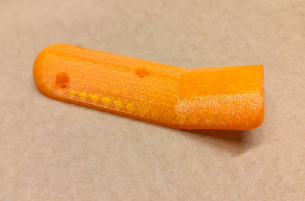
Handle
I designed with Solidworks a simple handle which holds all the electronics and make it more usable.
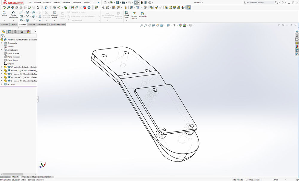
After i 3D printed the model and used some nylon spacers to fix the board and the joystick on top of it.
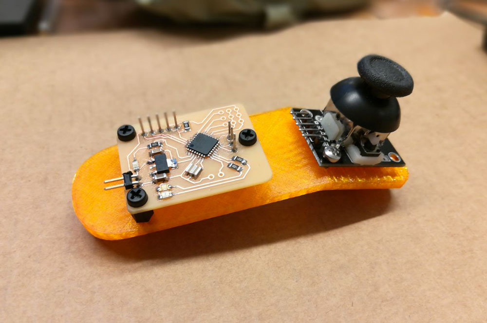
Testing the communication
I soldered the wires from the board to the joystick and bluetooth and uploaded a new code.
#define POT1 A0
#define POT2 A1
#define POT3 A2
#define BTN1 5
#define LED1 6
#define LED2 7
int pot1 = 0;
int pot2 = 0;
int pot3 = 0;
bool btn1 = false;
void setup() {
  Serial.begin(9600);
  pinMode(POT1, OUTPUT);
  pinMode(POT2, OUTPUT);
  pinMode(BTN1, INPUT);
  digitalWrite(LED1,HIGH);
  digitalWrite(LED2,HIGH);
  delay(1000);
  digitalWrite(LED1,LOW);
  digitalWrite(LED2,LOW);
}

void loop() {
  pot1 = analogRead(POT1);
  pot2 = analogRead(POT2);
  pot3 = analogRead(POT3);
  if(digitalRead(BTN1) == HIGH) {
    btn1 = true;
    digitalWrite(LED2,HIGH);
  }
  else {
    btn1 = false;
    digitalWrite(LED2,LOW);
  }
  Serial.print(pot1);Serial.print(";");
  Serial.print(pot2);Serial.print(";");
  Serial.print(pot3);Serial.print(";");
  Serial.println(btn1);
}
The video of the successful communication.