Objectives:
- Group: Find the kerf value. link
- Individual: Cut something on the vinylcutter. anchor
- Individual: Design, Make and Document a parametric press-fit construction kit.anchor
VinylCutter
Using FabModules
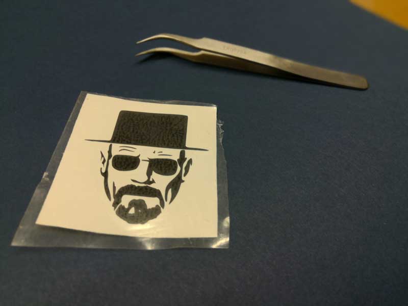
The first assignment of the week was to play with the vinylcutter. i downloaded from the internet a silhouette of a Maori Tattoo
To be able to use our VinylCutter, the Roland CAMM-1 GS-24 i had to download:
I loaded the image onto the fabmodules link , i selected PNG as input format and Roland Vinyl ( .camm ) as Output. The module calculated itself the cutting line and, after a quick visual check i downloaded the .camm file. The setting used for the cut are:
- Cutting Force: 70gf
- Cutting Speed: 5 cm/sec


To send the file to the vinyl cutter i used the command line of a Linux computer.
After checking if the Roland gs-24 was recognized by the computer i launched the command :
cat /path/to/file/filename.camm > /dev/usblp0

I peeled out the scraps of the sticker and used paper tape to transfer it to my locker

The final result is impressive considering how small the sticker is ( 40 x 40 mm ).
Download:
Roland GS-24 -> maori.camm (16Kb)
Using Roland CutStudio
From the OnSupport software, after creating a Roland Account, i was able to download Roland Cutstudio.
The program is really easy to use, after “scanning” the vinyl piece from the machine, CutStudio show a preview of the available cut area. I imported the png image into the program and extracted the image outline using the built in function.


The parameters of the first cut i tried were the default one:
- Cutting Force: 80gf
- Cutting Speed: 10 cm/sec
But at some point the cutting knife started to bend the vinyl and the cut didnt go as expected.
The second parameters were:
- Cutting Force: 70gf
- Cutting Speed: 7 cm/sec

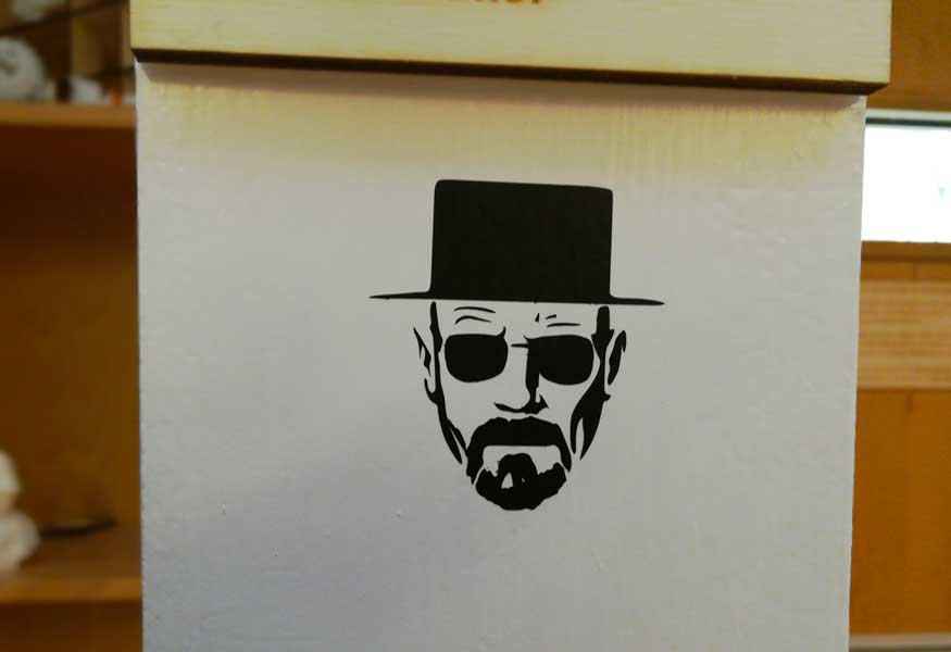
The cut came out great and was very easy to peel out the scraps.
I used the transfer paper to apply the sticker on a lab’s column
Press-Fit Kit
The second assignment of the week was to design and make a modular yet parametric kit.
The program i chosed to complete this assignment is SolidWorks because i've never used it for parametric design. Solidworks can be used to build parametric designs by creating variables and functions.
We used 5.7mm thick plywood, you can find the calculated kerf in the group assignment page. LINK
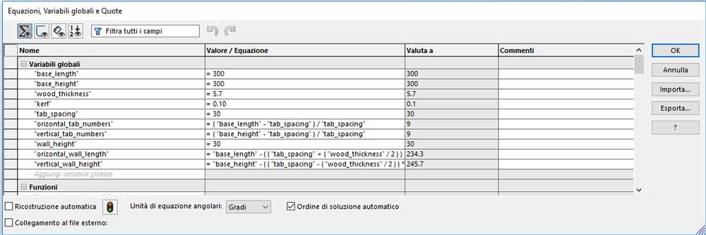
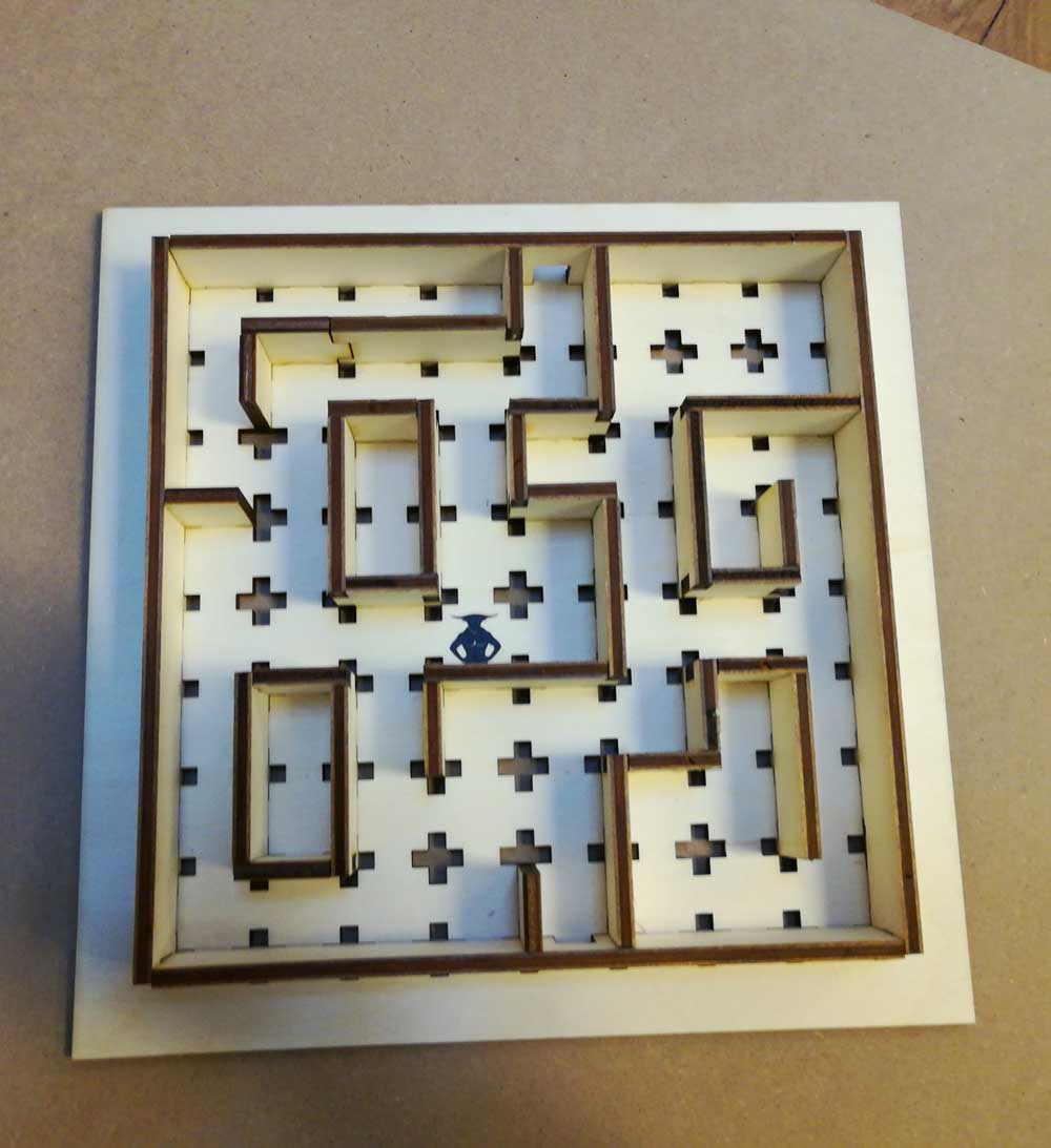
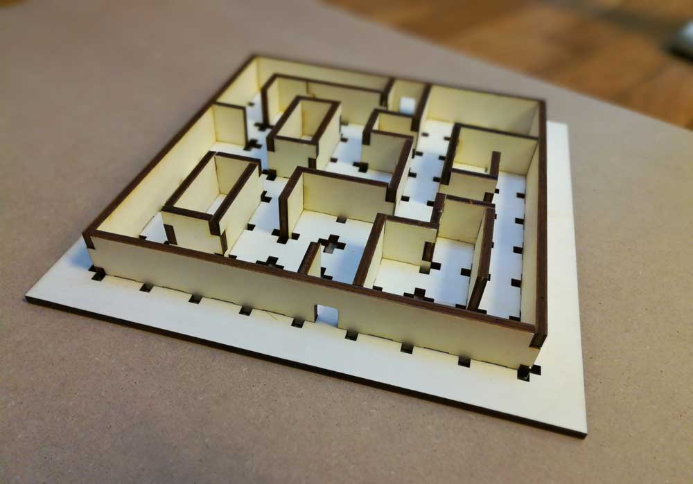
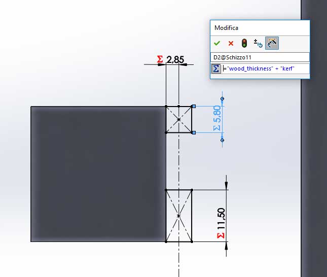
The kit i made is a modular maze. You can choose the base width and length, the wood thickness and the tabs spacing… and of course the calculated kerf for the wood. The design calculate itself the numbers of tabs for the given length/width and tab spacing; you have to make sure the tab spacing is a multiplier of the length and width otherwise the number of tabs will not be an integer and the design flaw.

The maze have four outer walls, two of them have a gate, the length of the outer walls is automatically calculated based on the length and width of the base.
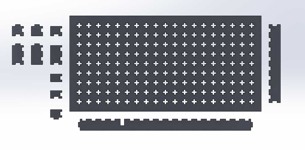
I designed the base, outer walls and inner walls in a single file because otherwise i had to write the same variables for each part. To check if everything fits, under the solid bodies menu of solidworks,you can save each body as a single part and then create an assembly.
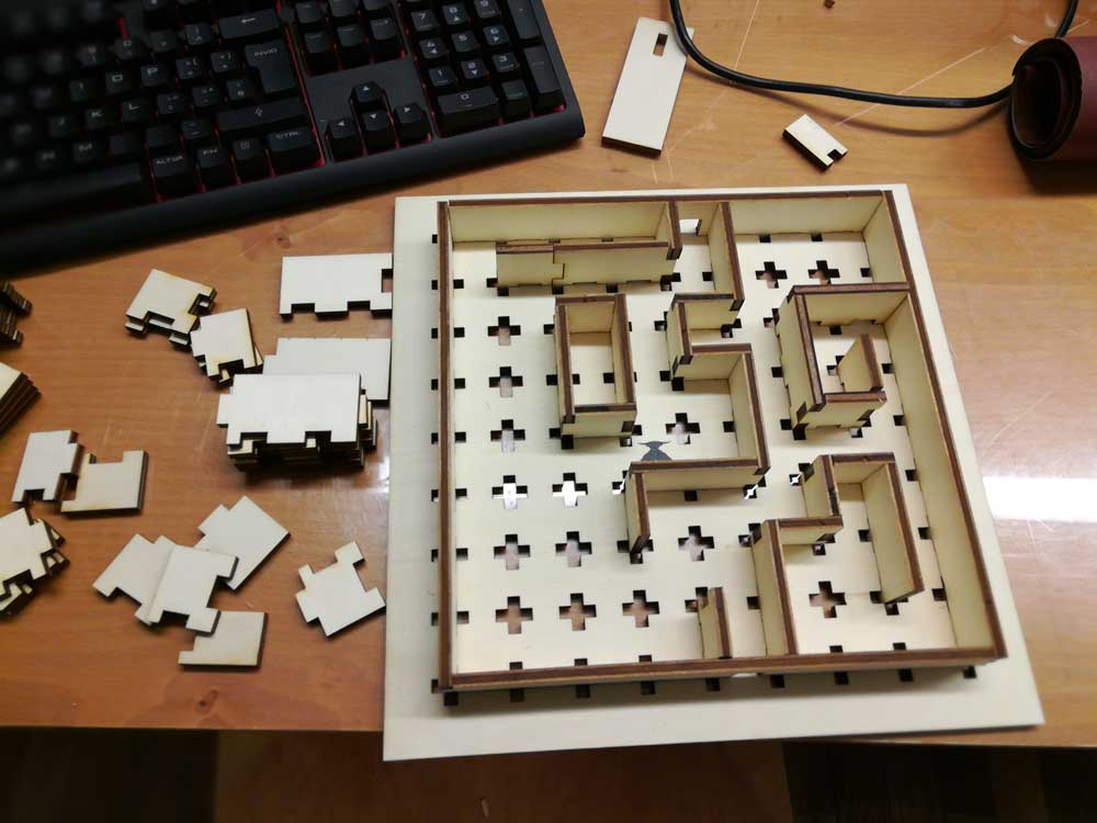
The kerf calculated at the beginning worked good for the first cuts but, since in the lab we are six people, and everyone was cutting, the lenses of the lasercut became dirt and the kerf did increase. Another thing to take care of is the wood warpness; if you focus the beam on the higher point of the warp than on the lower side isn't focused and vice versa.