Objectives:
- Make an in-circuit programmer by milling the PCB. Milling, BOM, Soldering, Programming and testing
The FabOptimus ISP programmer
The assignment of this week was to build an In-System Programming ( ISP ) board.
I decided to build the FabOptimus version of the FabIPS because it's well documented and explain in a thorough way how every components work. Link to the project page
Milling the PCB
In our lab we have a Roland srm-20 CNC machine, always plugged into a computer with VPanel installed.
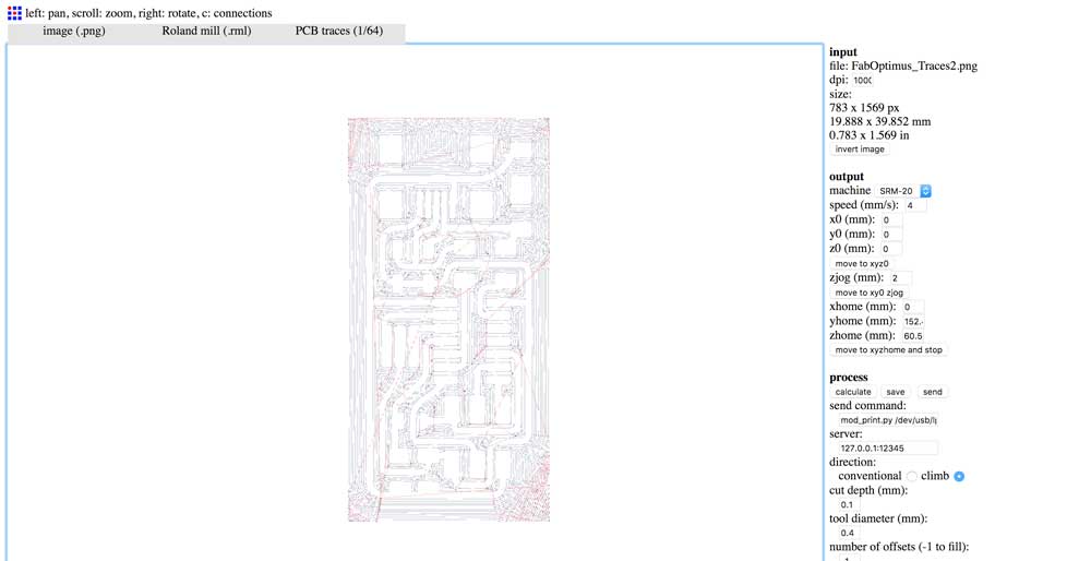
I downloaded the Traces and Outlines of the FabOptimus. Using the fabmodules.org i generated the cutting files.
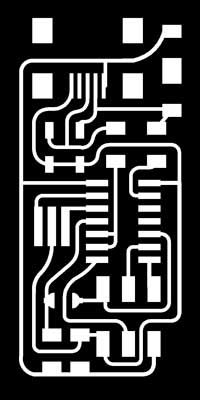

For the Outline i used a 1/64 end mill, leaving all the default fab modules values except for the numbers of outlines where i inputted -1 which stands for “do outlines til the board is clean”. For the traces i used 1/32 end mill, with standard cutting parameters.
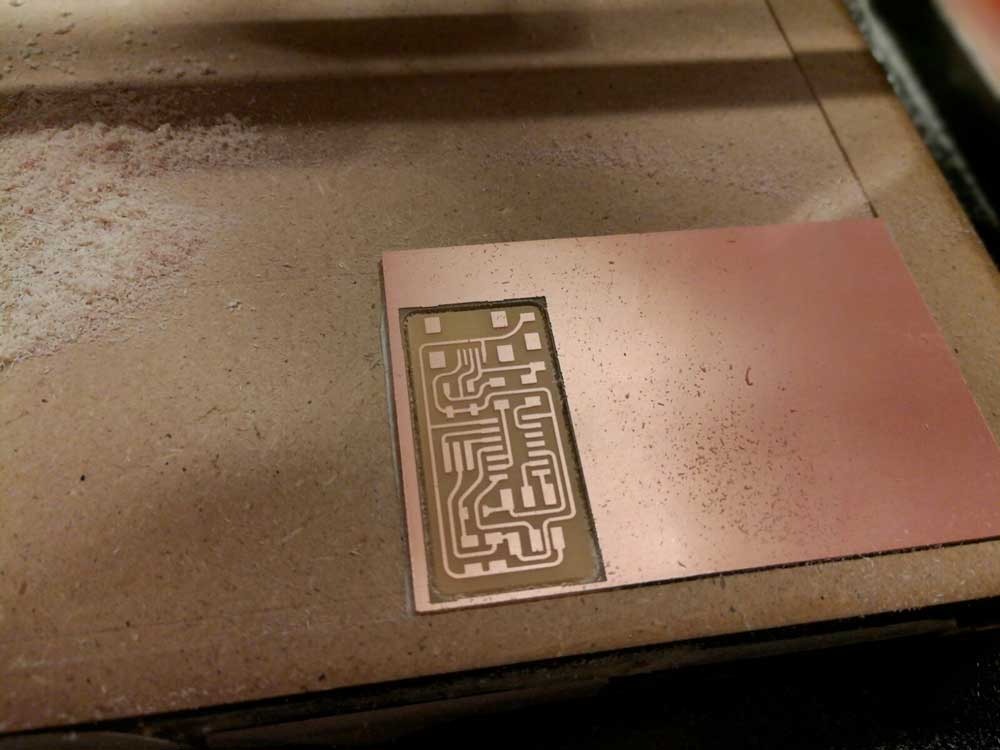
The Roland works in a very simple way, you have to zero the XY coordinates on the bottom-left of the pcb than move down the z axis until the tip is close to the copper. Next you untight the end mill and let it drop on the copper than tight it again and set the Z axis zero on the Vpanel. After move up the Z axis a bit so, when the spindle starts, it doesn't leave a scratch on the board and launch the milling file. After the outline milling i had to swap the end mill with the 1/32 one and zero the Z axis again, leaving the XY zeros untouched; then launched the outline code.
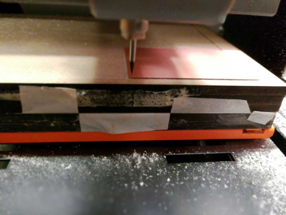
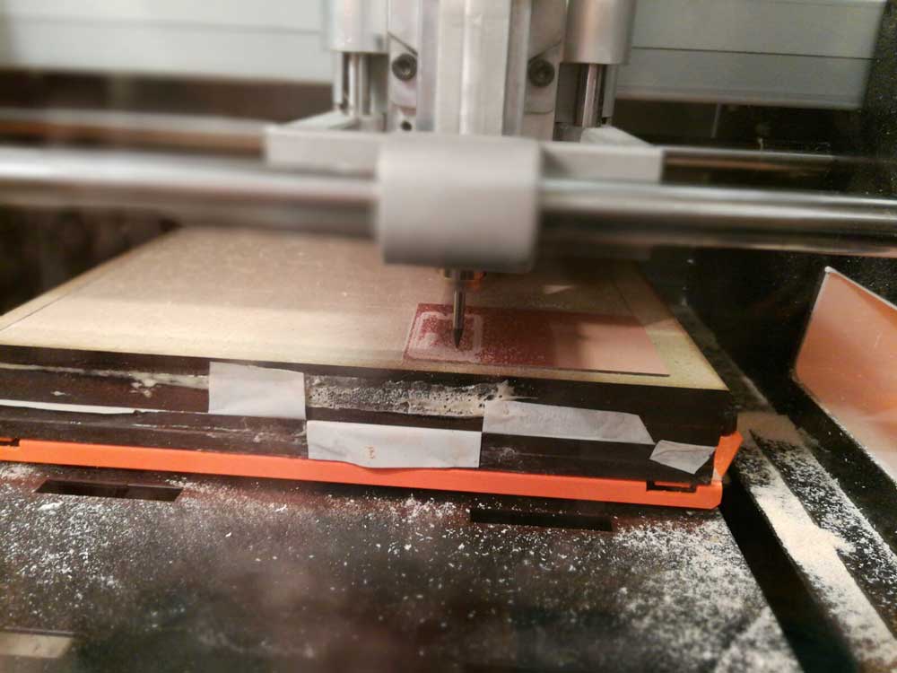
PS: I used double-sided adhesive tape to keep the pcb in place.
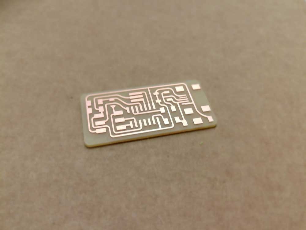
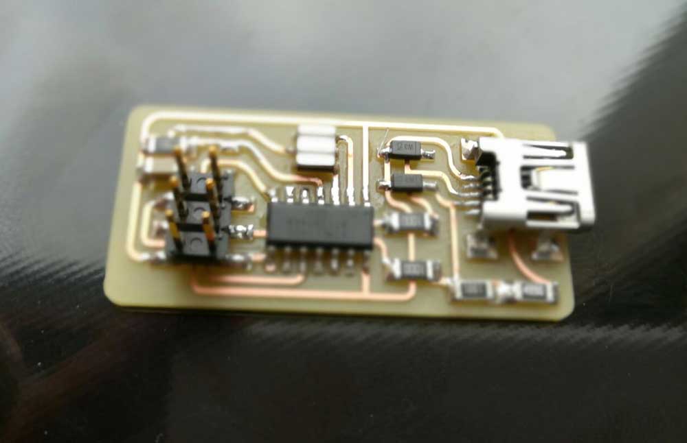
The pcb came out really good and flawless. I cleaned it with water and soap to remove the milling particle left in between the traces.
Bill of Materials ( BOM )
Before starting to solder i gathered all the materials needed to complete the board.
( I have to confess that my mate, Simone, did the dirty job for me :P )
| Name | Quantity |
|---|---|
| ATTiny44 | x1 |
| 100Ω Resistor | x2 |
| 100kΩ Resistor | x1 |
| 1kΩ Resistor | x1 |
| 499Ω Resistor | x1 |
| 0Ω Jumper Resistor | x1 |
| 1μF Capacitor | x1 |
| Zener Diode | x2 |
| 20MHz Resonator | x1 |
| 6 pin SMD header | x1 |
Soldering the components:
For the people who wants to learn how to solder, in a very old school way, i suggest reading this NASA technical standard paper from 1997:
http://snebulos.mit.edu/projects/reference/NASA-Generic/NASA-STD-8739-3-2.pdf
Our soldering station is a Lafayette ssd-87, it had a standard soldering pen and a soldering air gun and can go up to 480 degree.
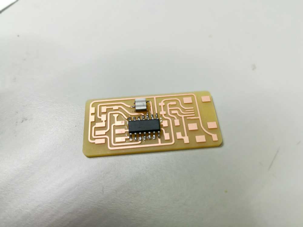
I setted the temperature to 350C and started soldering from the hardest component: the ATTiny44 and so on with the other components.
Programming and Testing:
Since i’m using a Mac with MacOS 10.12.1 i had to install XCode and CrossPack for AVR.
To learn how to program the board i followed the suggested tutorial:
http://archive.fabacademy.org/archives/2016/doc/programming_FabISP.html
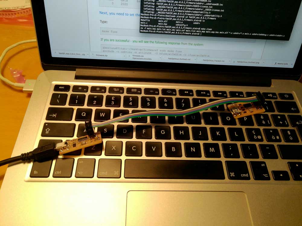
Before starting i connected the board with a 6 wire connector to another working programmer, the latter to a computer with a mini USB cable.
 I downloaded the firmware from the link above and extracted into my Desktop with the command
unzip fabISP_mac.0.8.2_firmware.zip -d /Users/pietro/Desktop/
I navigated to the unziped folder and edited the Makefile file with nano
cd /User/pietro/Desktop/fabISP_mac.0.8.2_firmware
Next i removed the # in front of the line with "usbtiny" and added # to beginning the line with the "avrisp2" to comment it out.
nano Makefile
Ctrl + O to save the file
Ctrl + X to exit
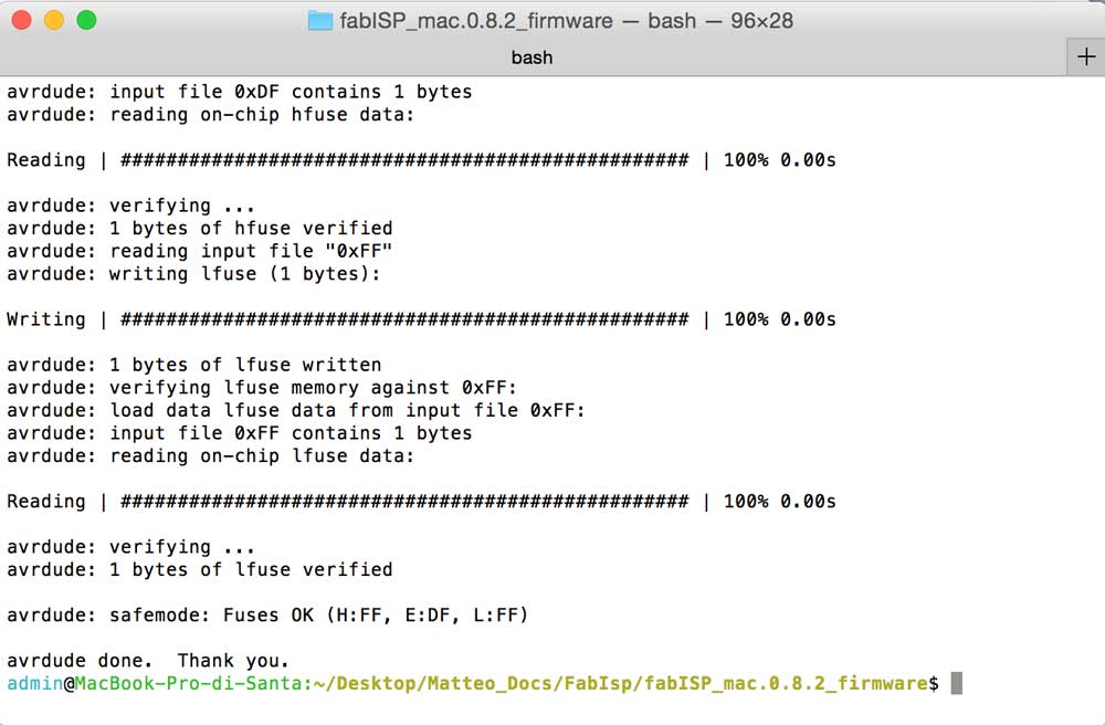
Then i executed make clean , make hex, make fuse, make program. Everything worked as expected.
Understanding what we did above
Make clean:
If we look inside the Makefile, we can find the part of the code where the make clean is defined:
                clean:

                  rm -f main.hex main.lst main.obj main.cof main.list main.map main.eep.hex main.elf *.o usbdrv/*.o main.s usbdrv/oddebug.s usbdrv/usbdrv.s
The rm command is used to delete files, in this case the files listed after the command. The -f option is used to ignore the non-existent files. We use make clean to be sure that, every file we will create after, are brand new and does not refer to older builds.
Make hex:
It takes the source code and build the hex file which is machine code.
Make fuse:
Make fuse “flash” 3 bytes into the registers of ATtiny44, each byte has his own meaning.
The first byte, named Fuse Extended Byte, have only one programmable bit ( the first ), if we set it to 1 we enable the SPM (Self-Programming Mechanism) .
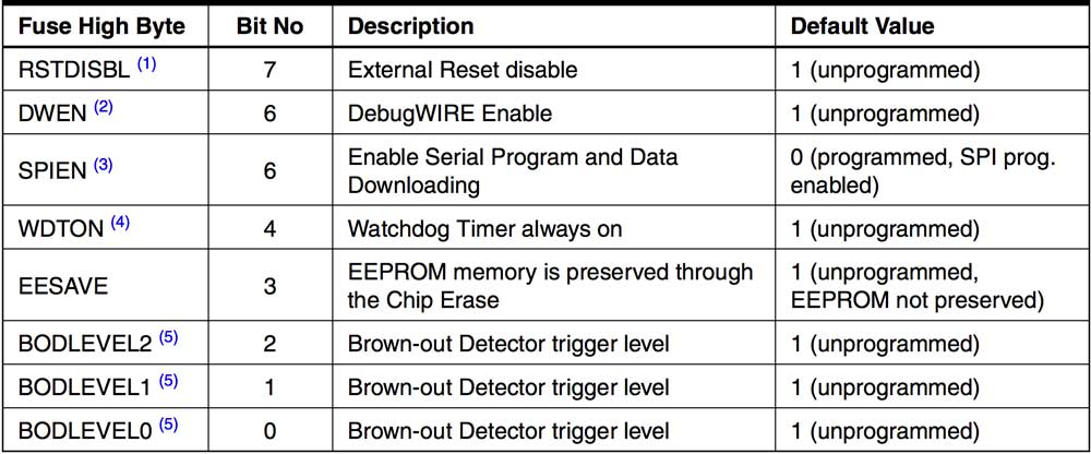
The second byte, named Fuse High Byte, is used to select the behaviour of the ATtiny.
See table below.
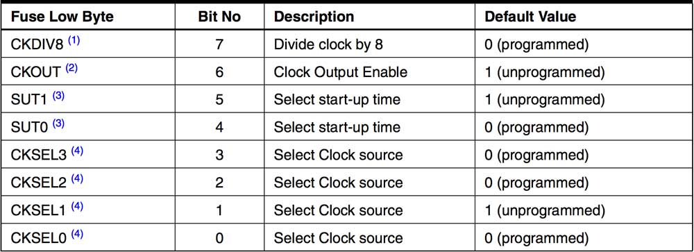
The third byte is used to select the clock source ( in our case external 20mhz ) and the clock scaler.
See table below
Make program:
Make program take the hex file created before and load it into the ATtiny.
Testing
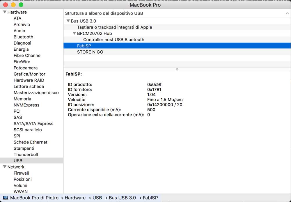
To test the board, i first removed the 0 ohm jumper resistor, then i checked if my computer recognized it as FabISP and it did.
As final test i used my board to flash the firmware of another FabISP.
Conclusions
I noticed that FabISP have some problems with USB 3.0 ports, to avoid this problem i used an usb extension cable. I suggest everyone to double-check connections and try differents programmers and/or OS to flash the firmware.