Objectives:
- Create a working code to control the robot. The Software, The App The Video
The Software
The first step was to identify which pin correspond to each input/output, i used the atmega 328p and the schematic to find them:
#define SERVO1 5
#define SERVO2 6
#define MOSFET 9
#define BUZZER 10
#define INTERRUPT_PIN 2
After i downloaded the libraries i needed:
- PID_v1 https://github.com/br3ttb/Arduino-PID-Library
- I2C dev + MPU6050 https://github.com/jrowberg/i2cdevlib/tree/master/Arduino/MPU6050
And included the Wire.h needed to make the i2c dev library works and the servo library.
I used as starting point the MPU6050 DMP example and included the PID routine and the bluetooth serial communication, below the resulting code:
#include "I2Cdev.h"
#include "MPU6050_6Axis_MotionApps20.h"
#include "Wire.h"
#include < Servo.h >
#include < PID_v1.h >

#define SERVO1 5
#define SERVO2 6
#define MOSFET 9
#define BUZZER 10

// -------- IMU ------------
MPU6050 mpu;
#define INTERRUPT_PIN 2
bool dmpReady = false;
uint8_t mpuIntStatus;
uint8_t devStatus;
uint16_t packetSize;
uint16_t fifoCount;
uint8_t fifoBuffer[64];
Quaternion q;           // [w, x, y, z]         quaternion container
VectorFloat gravity;    // [x, y, z]            gravity vector
float ypr[3];           // [yaw, pitch, roll]   yaw/pitch/roll container and gravity vector
volatile bool mpuInterrupt = false;
// -------- SERVO ------------
Servo servoONE,servoTWO;
// -------- PID ---------------
double Setpoint, Input, Output;
PID rollPID(&Input, &Output, &Setpoint,2,1,0, DIRECT);
// --------- OTHER -----------
int state;

void setup() {
    Wire.begin();
    Wire.setClock(200000);
    Serial.begin(9600);
    mpu.initialize();
    pinMode(INTERRUPT_PIN, INPUT);
    initMPU();
    pinMode(MOSFET,OUTPUT);
    servoONE.attach(SERVO1);
    servoTWO.attach(SERVO2);
    delay(300);
    servoONE.write(80);
    servoTWO.write(80);
    delay(300);
    Input = 0;
    Setpoint = 0;
    rollPID.SetMode(AUTOMATIC);
    rollPID.SetOutputLimits(-30,30);
}
void loop() {
  motion();
  updateAngle();
  Input = ypr[1]* 180/M_PI;
  rollPID.Compute();
  servoONE.write(80+Output);
  servoTWO.write(80-Output);
}

void updateAngle(){
    if (!dmpReady) return;
    while (!mpuInterrupt && fifoCount < packetSize) {

    }
    mpuInterrupt = false;
    mpuIntStatus = mpu.getIntStatus();
    fifoCount = mpu.getFIFOCount();
    if ((mpuIntStatus & 0x10) || fifoCount == 1024) {
        mpu.resetFIFO();
    } else if (mpuIntStatus & 0x02) {
        while (fifoCount < packetSize) fifoCount = mpu.getFIFOCount();
        mpu.getFIFOBytes(fifoBuffer, packetSize);
        fifoCount -= packetSize;
        mpu.dmpGetQuaternion(&q, fifoBuffer);
        mpu.dmpGetGravity(&gravity, &q);
        mpu.dmpGetYawPitchRoll(ypr, &q, &gravity);
    }
}
void initMPU(){
    devStatus = mpu.dmpInitialize();
    mpu.setXGyroOffset(220);
    mpu.setYGyroOffset(76);
    mpu.setZGyroOffset(-85);
    mpu.setZAccelOffset(1788);
    if (devStatus == 0) {
        mpu.setDMPEnabled(true);
        attachInterrupt(digitalPinToInterrupt(INTERRUPT_PIN), dmpDataReady, RISING);
        mpuIntStatus = mpu.getIntStatus();
        dmpReady = true;
        packetSize = mpu.dmpGetFIFOPacketSize();
    } else {
        Serial.write("errore");
    }
}
void dmpDataReady() {
    mpuInterrupt = true;
}
void motion() {
  if(Serial.available() > 0){
      state = Serial.read();
  }
  if (state == 'S') {
      Setpoint = 0;
      digitalWrite(MOSFET,LOW);
  }
  else if (state == 'F') {
      digitalWrite(MOSFET,HIGH);
      Setpoint = 0;
  }
  else if (state == 'L') {
      Setpoint = 10;
  }
  else if (state == 'R') {
      Setpoint = -10;
  }
  else if (state == 'Q') {
      digitalWrite(MOSFET,HIGH);
      Setpoint = 10;
  }
  else if (state == 'E') {
      digitalWrite(MOSFET,HIGH);
      Setpoint = -10;
  }
}
To summarize the code working principles:
Each loop the code reads from the MPU6050 the current rolling angle and send it to the PID algorithm which take the desired setpoint and the current angle and output the servo position.
The bluetooth receive six commands from the serial:
- F ( Forward ): The mosfet make the motors spin and the angle setpoint is 0
- R ( Right ): The mosfet stops the motors and the setpoint is 10 ( degrees )
- L ( Left ): The mosfet stops the motors and the setpoint is -10 ( degrees )
- E ( Forward - Right ): Motor spins and setpoint = 10
- Q ( Forward - Left ): Motor spins and setpoint = -10
- S ( Stop ): Motors off, PID off
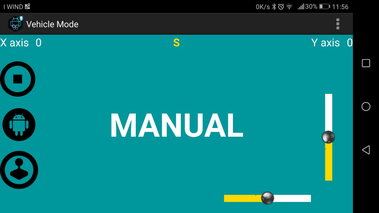
The App
I downloaded the Arduino Bluetooth Controller from the Android Playstore PAGE LINK
The app let you connect to a bluetooth device scanned and listed on the app, then you can setup a character that will be sent to the host for each gesture on the phone.


When everything is set up you use the phone as remote controller