Objectives:
Intro
The assignment of the week was to design and build something big.
Our instructor gave us a plank of OSB wood sized 2400x1250x18 mm ( 94” x 49” x 0.7” ) which fit the whole CNC cutting table.
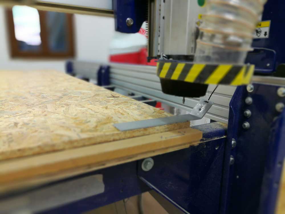
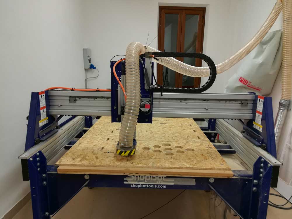
Our machine is a ShopBot PSR Alpha it's very powerful and require a lot of carefulness while using it.
I decided to use a Onsrud 1/4 flat , 2 flute , end mill to do every step of my cut.
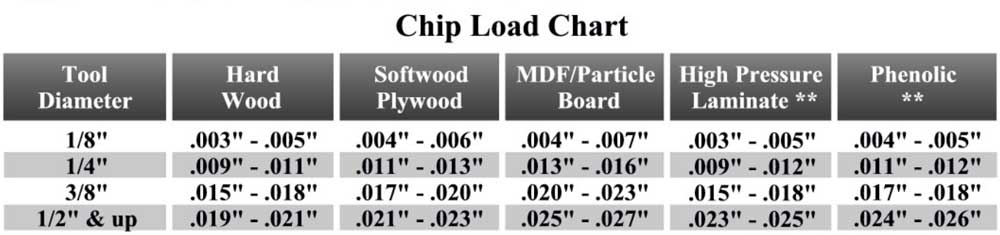
 To get an idea of the optimal cutting speed i followed the rules listed below:
FORMULAS:
Chip Load = Feed Rate / (RPM x # of cutting edges)
Feed Rate = RPM x # of cutting edges x chip load
Speed (RPM) = Feed Rate / (# of cutting edges x chip load)
So having the Spindle set at 12000 rpm , number of cutting edges at 2 , and chipload at 0.010”:
Feed Rate = 12000 x 2 x 0.010 = 240 inch/min = 100 mm/sec
From previous test we know that 240 inch/min of feed rate is too much for our machine ( or at least the cut scream very bad ) so we used 70 inch/min with a pass depth of 3mm ( total of 6 passes ).
Design
My first idea was to make a furniture to hold the vacuum forming machine but i found out that the plank we had wasn't big enough to make it.
So i decided to build a rack to store the sheets of wood/plexiglass we use with the lasercut.
To size the rack i measured the working area of our laser cut machine: the smaller side is 610 mm so i designed the rack width to be 640mm.
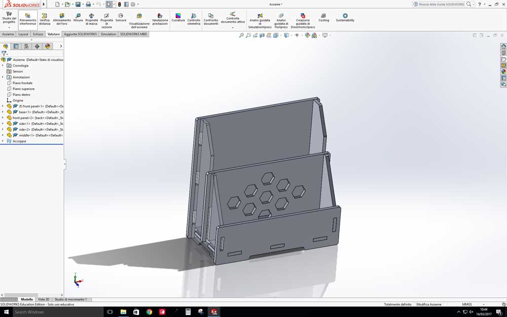
To design it i used the Software Solidworks, i created every single part and assembled it to check if everything was joining correctly.
From Solidworks , to export as 2D drawing, i saved it as DXF file and selected the face of the 3D model i wanted to export.
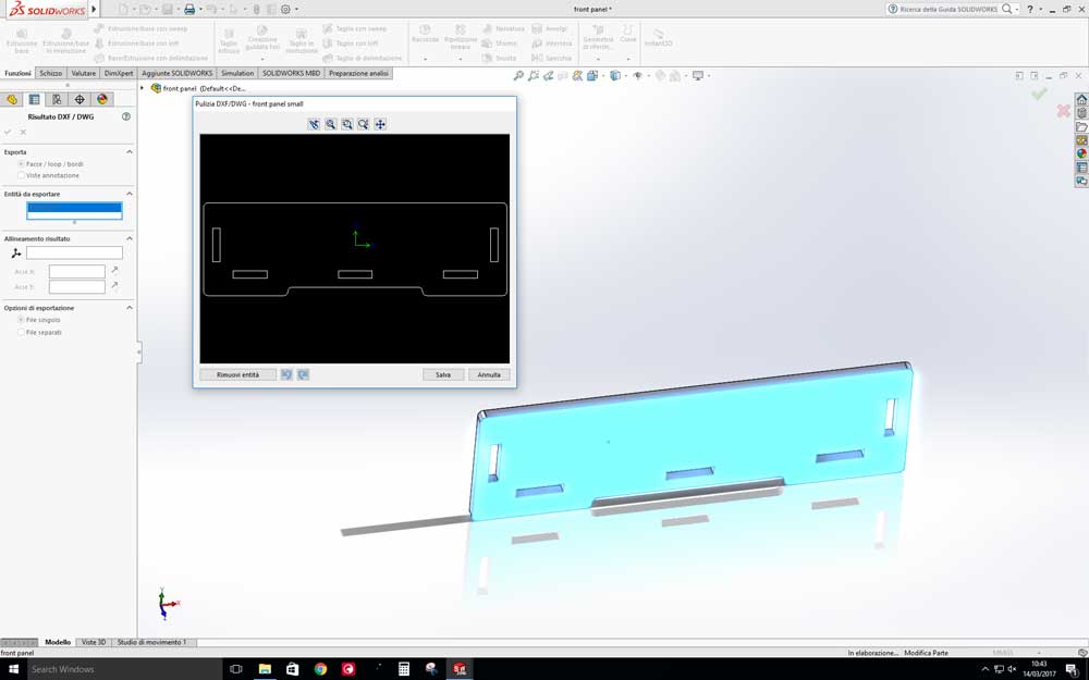
To “compose” the full cut file i used Adobe Illustrator i also had to close every shape because Solidworks export them as lines.

Cut
Before creating the toolpaths we had to get the machine ready.
The first thing we did was to clean the sacrificial bed from the previous cuts , after we started a warm up routine to get the spindle ready.
Next we inserted the 1/4 end mill into the collet and tighten it up.
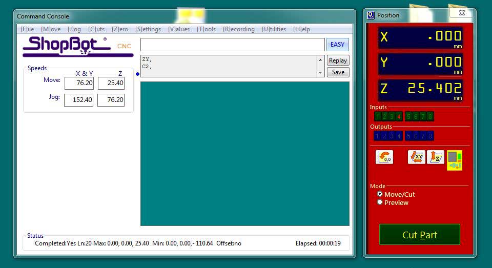
After we used the Z zero probing plate to set the machine zero of the Z axis and we manually moved the head to the very bottom left of the wood piece and zeroed the X and Y axis.
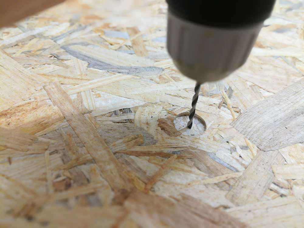
To fix the plank to the machine bed we created a 2mm pocket toolpath to mark the spots where we applied the screws. Those spots are outside of the real forniture cut so we know that the machine is not going to collide on them neither going out the the plank.

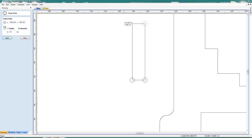
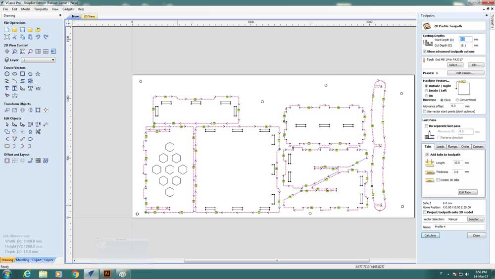
I created the t-bone holes with the VCarve program directly on the corners of the cuts. This procedure is made very easy with the snap tool vcarve provide.
I cutted all the inner parts of the design so i could apply more screws to hold the plank flat ( it was very warped )
When the inner toolpath was done i created the outline cut. I manually applied tabs to hold the pieces stable even at the last cutting pass. The tabs i used are 10mm long, 2mm thick.
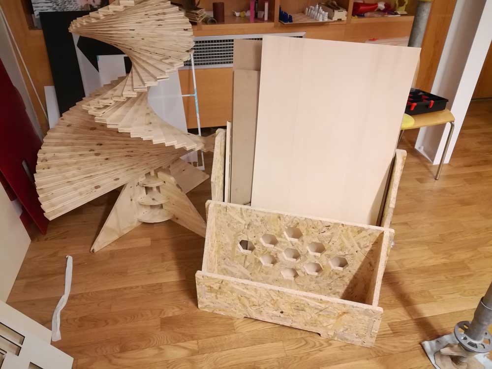
Assembly
Before starting to assemble the furniture i used the sandpaper to chamfer the edges.
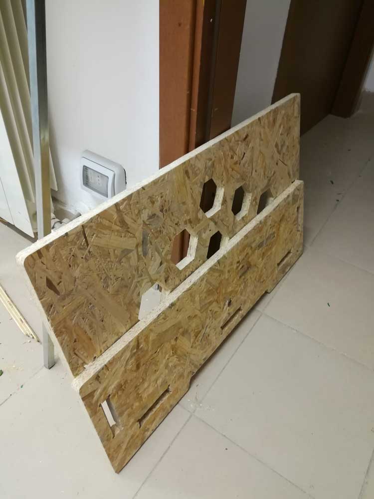
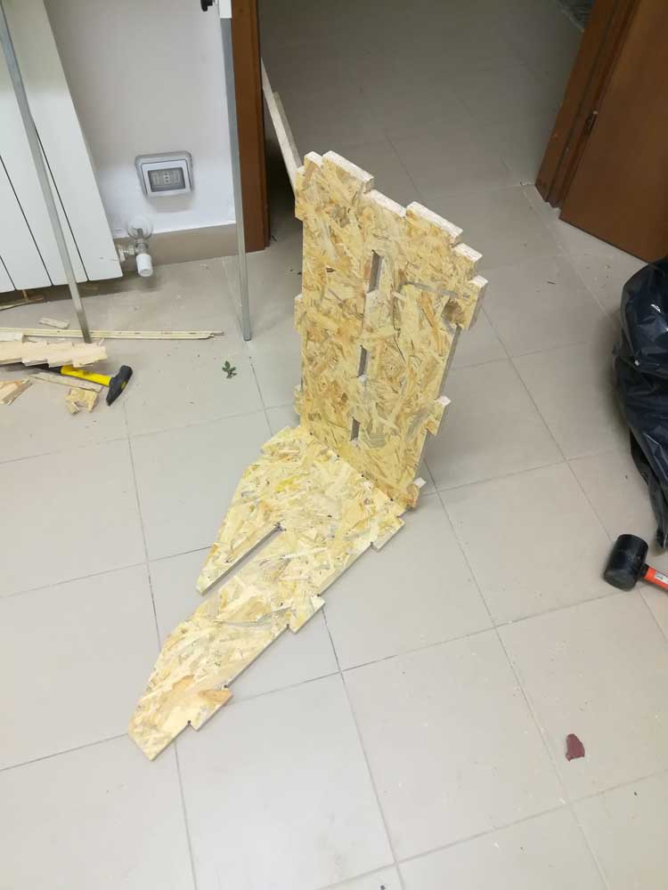
I started by joining the 2 sides with the base of the forniture. Next i mounted the back panel, it was very hammer-fit.
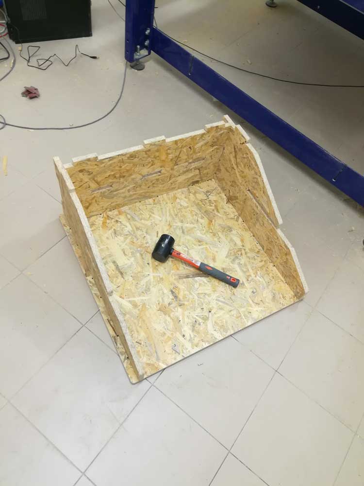
After the rack was done i used the sandpaper to give a better finishing and checked if the dimensions were correct.