
Final Project
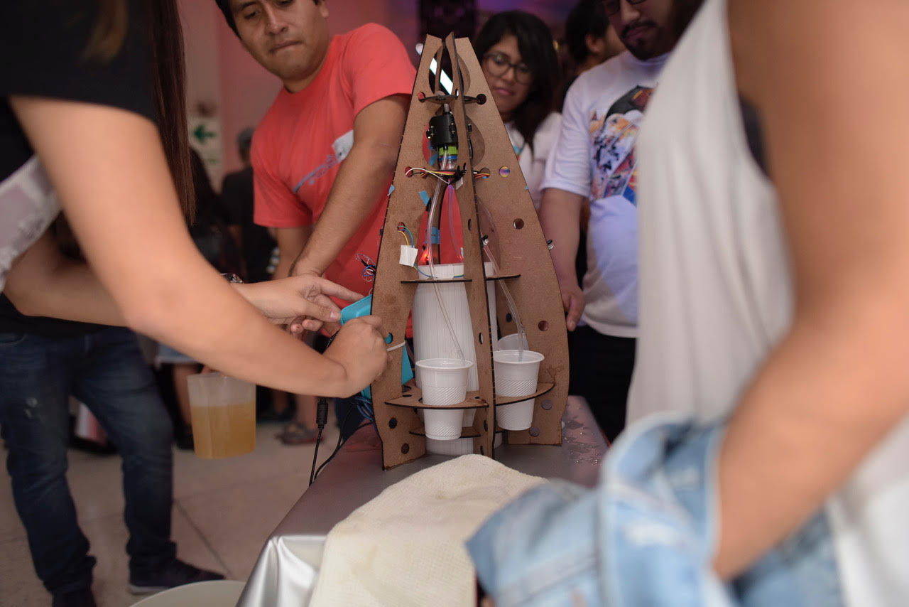
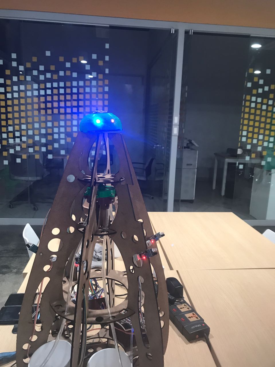
This page details each part of my final project which is a parallel water dispenser with
human interation around the machine. The main reason to create was to show some attractive in digital fabrication,
it had a part of social game to meet people in a party. The game was to find people with the same colour ticket, after that
they moved around the machine and put their hands over IR sensors on the machine. The project will details in the three next sections:
structure machine, electronics and programming
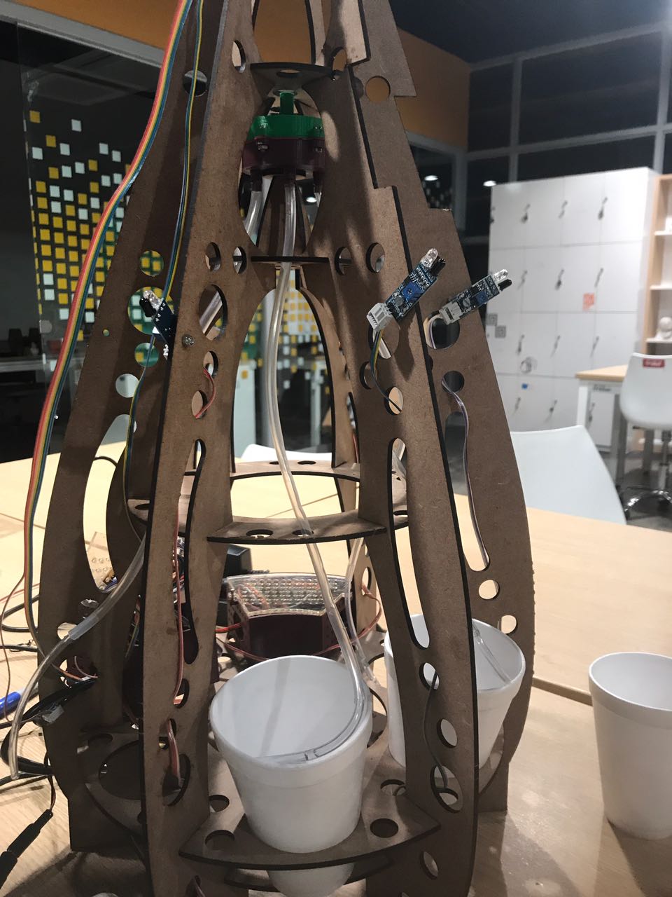
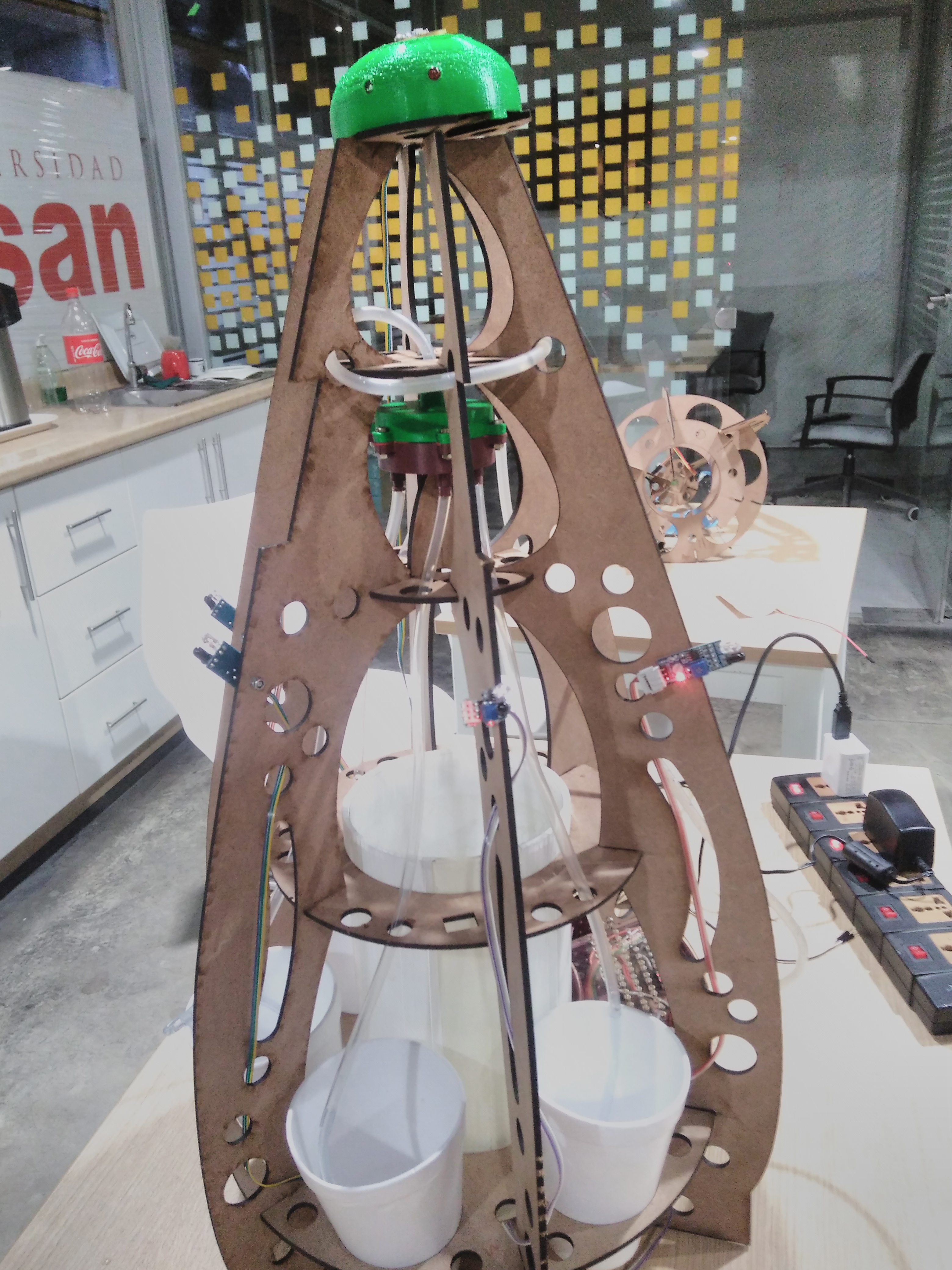
Structure machine
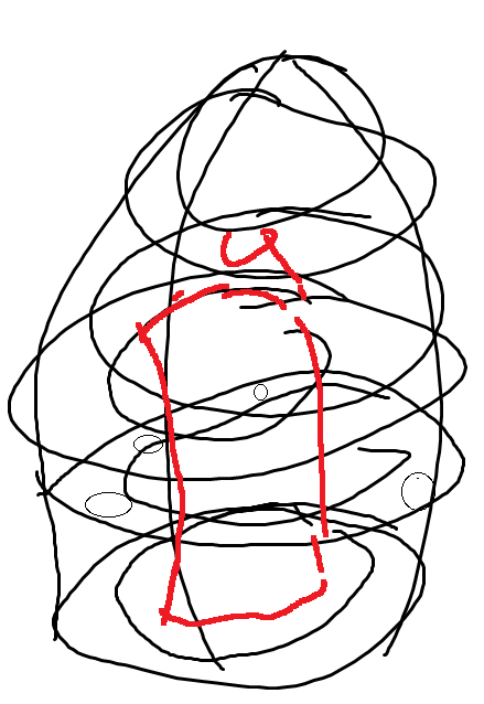
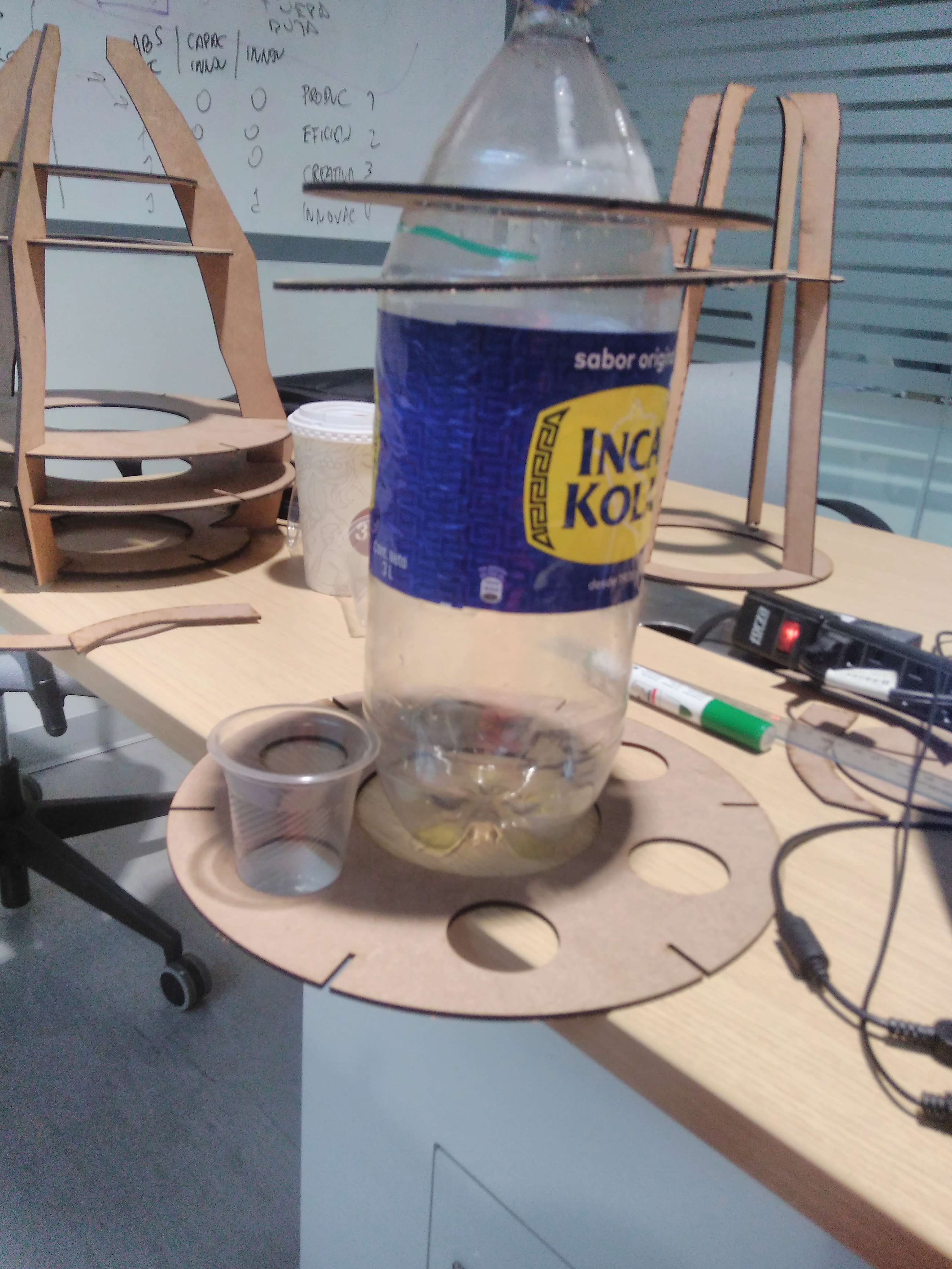
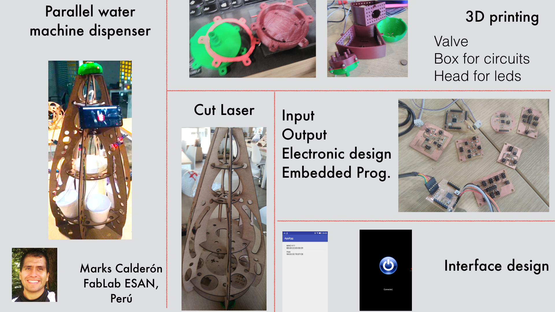
The initial idea was to make a simple dispense, so this designed shows in the right image and its restriction was dispensed one each time, but if the event has 300 people and only 60 minutes to social interation. It was impossible to have a single dispense. Therefore, we challenge to create a machine that distributes drinking in parallel. The result of this challenge was a new machine with egg shape. It will distribute six glasses .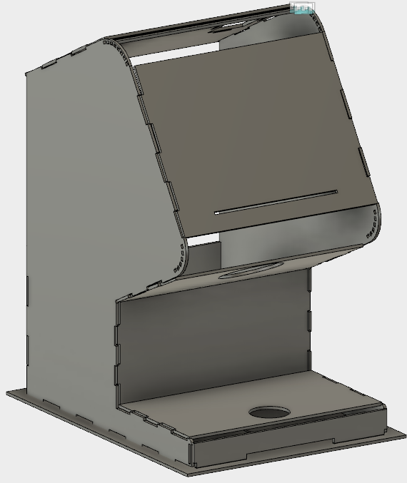


3D printing
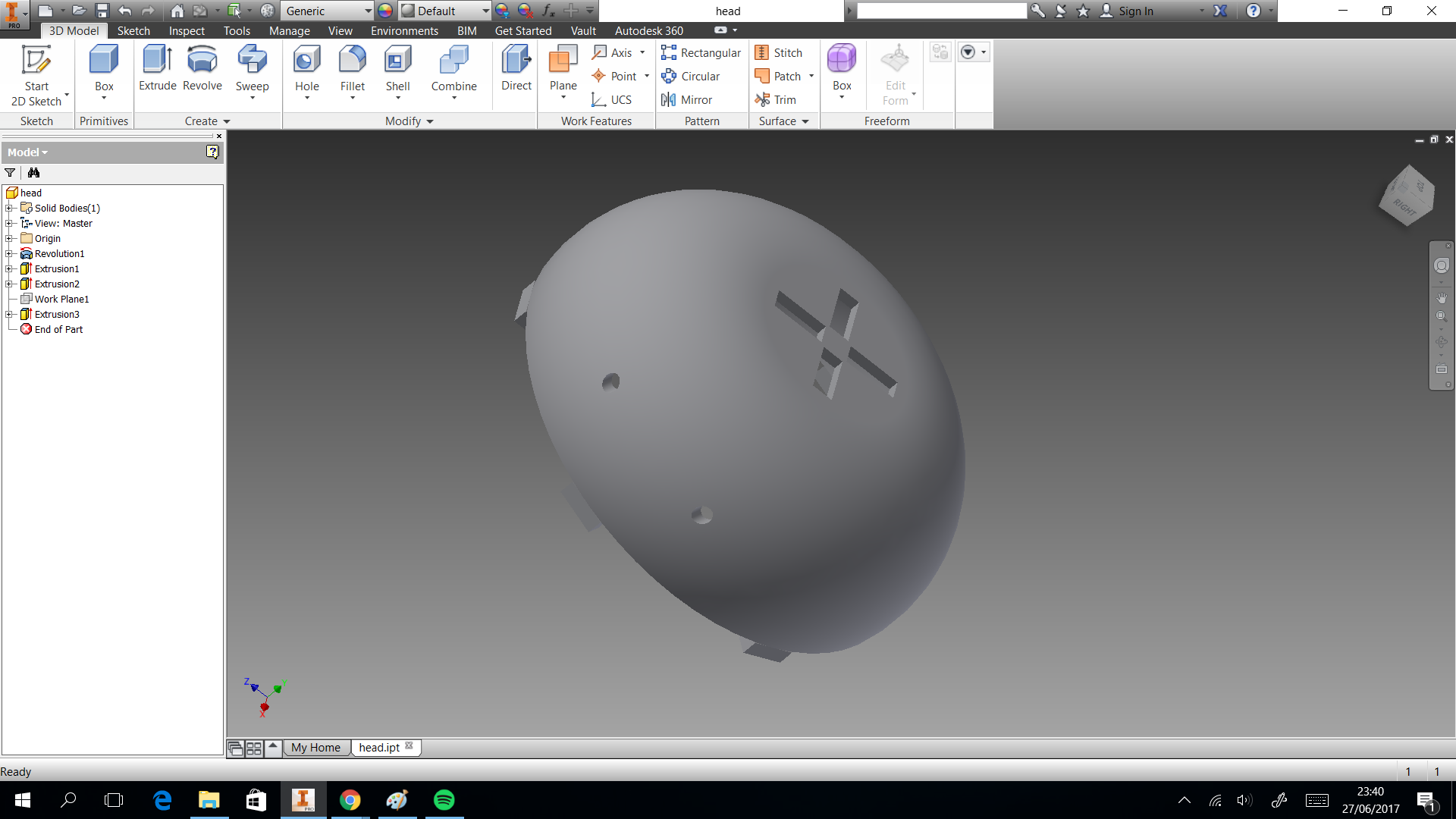
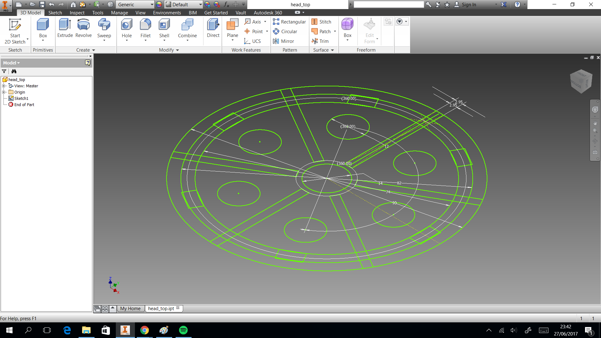
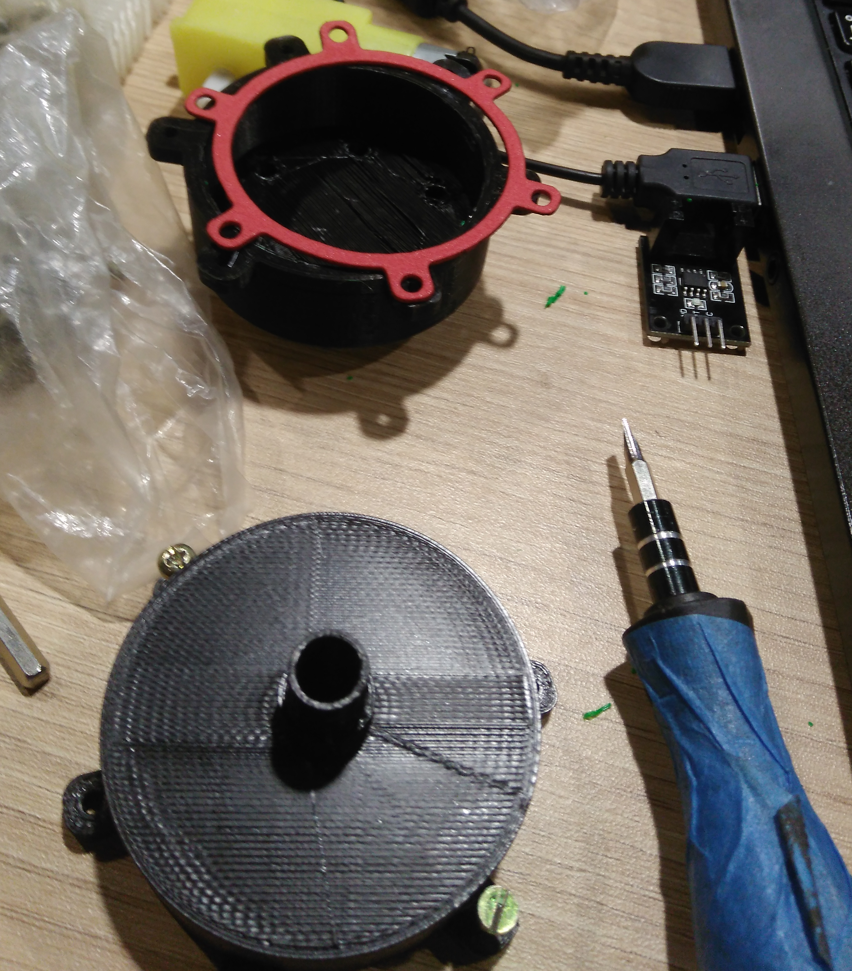
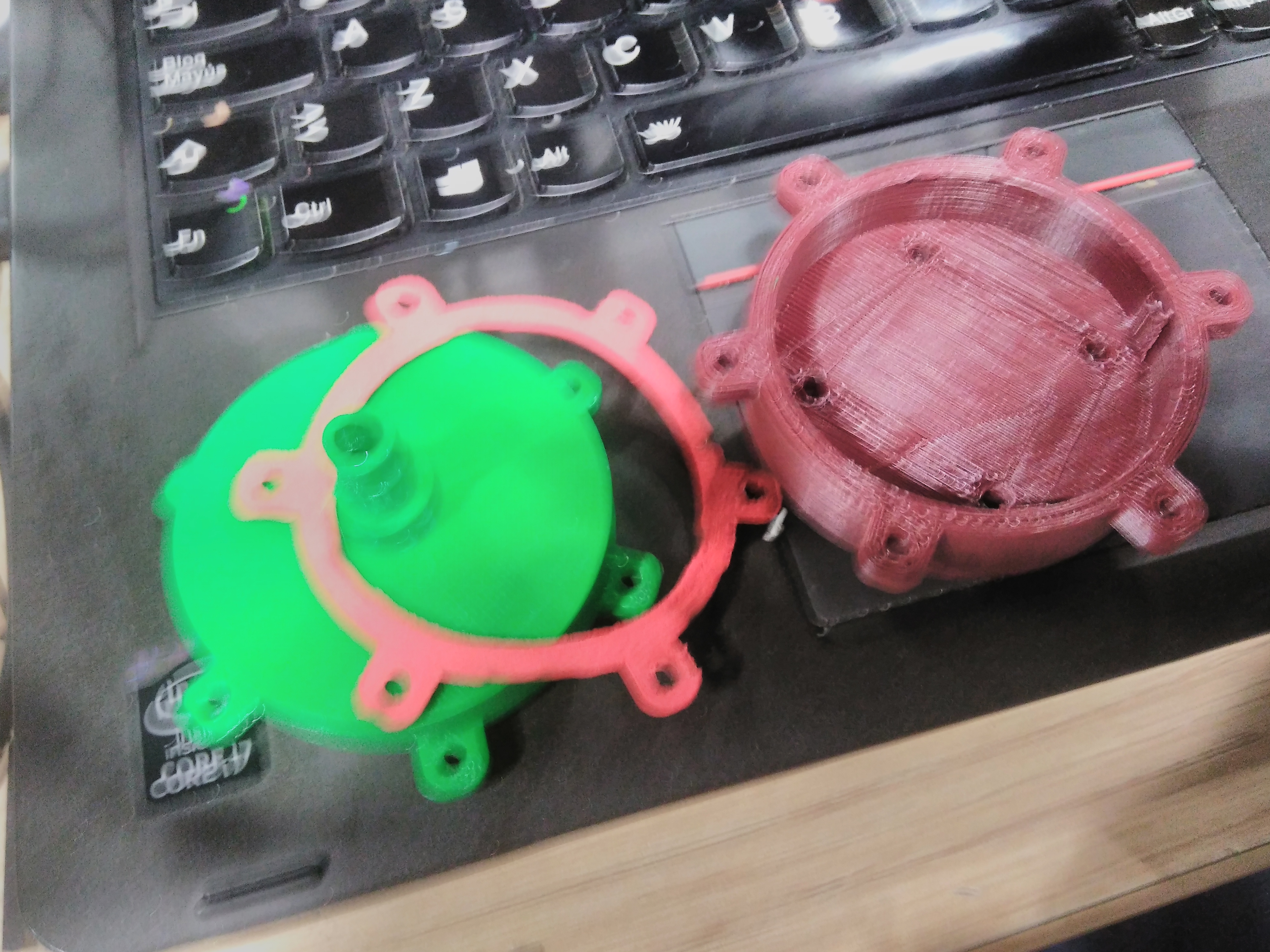
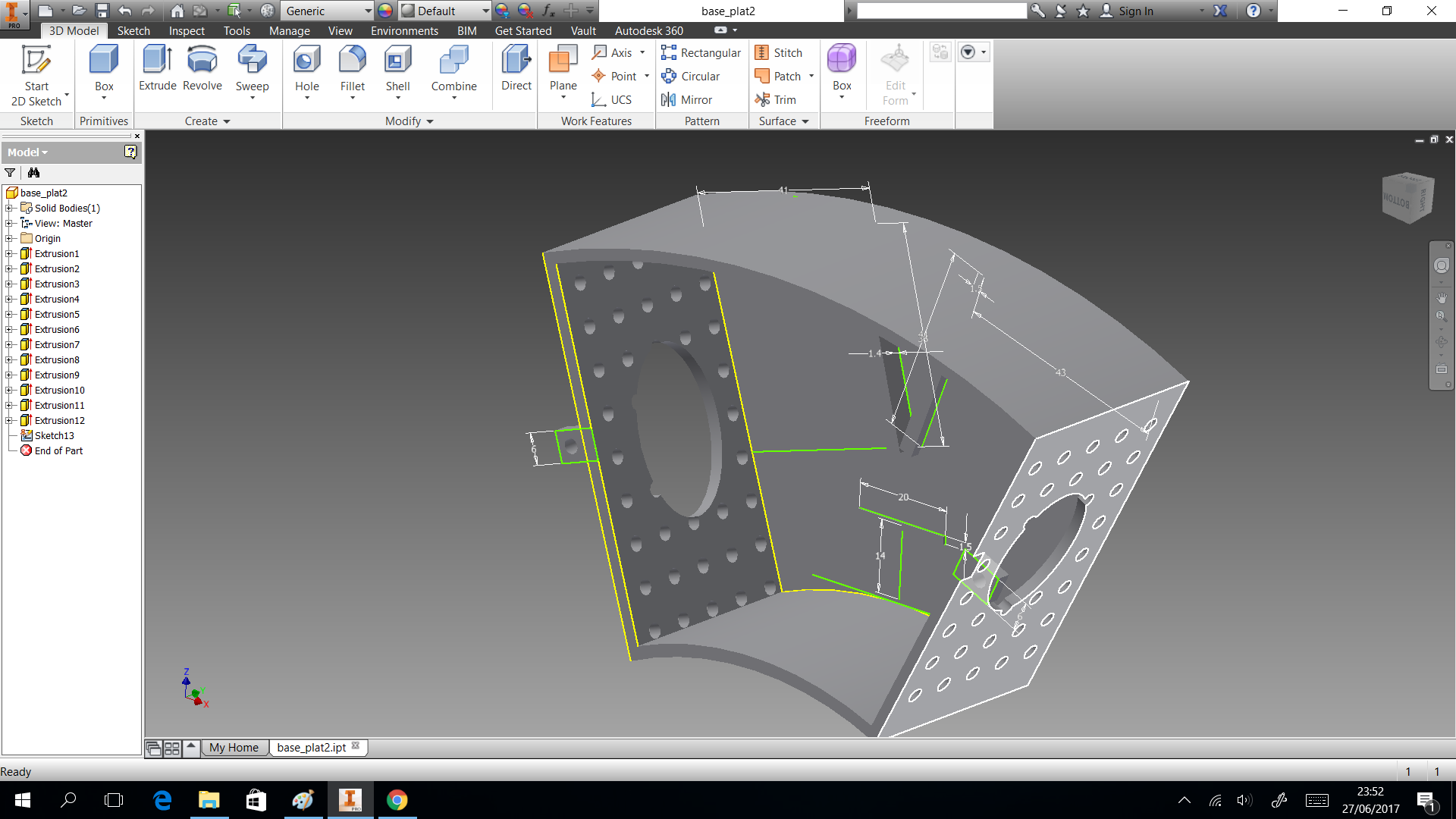
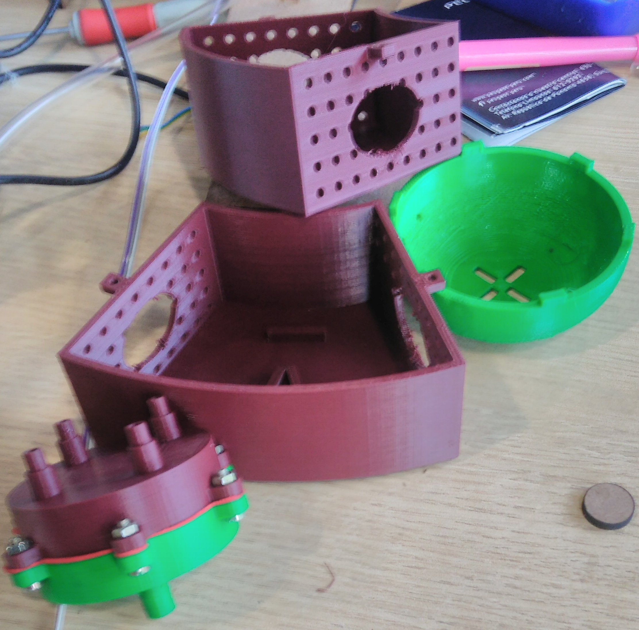
In this section we describe the 3D printing that we created. Three things designed here: head of machine , a valve and box to put the circuits. The first one was created to put leds and IR sensor, they are able when the machine is able to dispense or start the connection. A head complementary was a MDF desgin to fix with the supports. This design shows in the next images and can download the CAD files
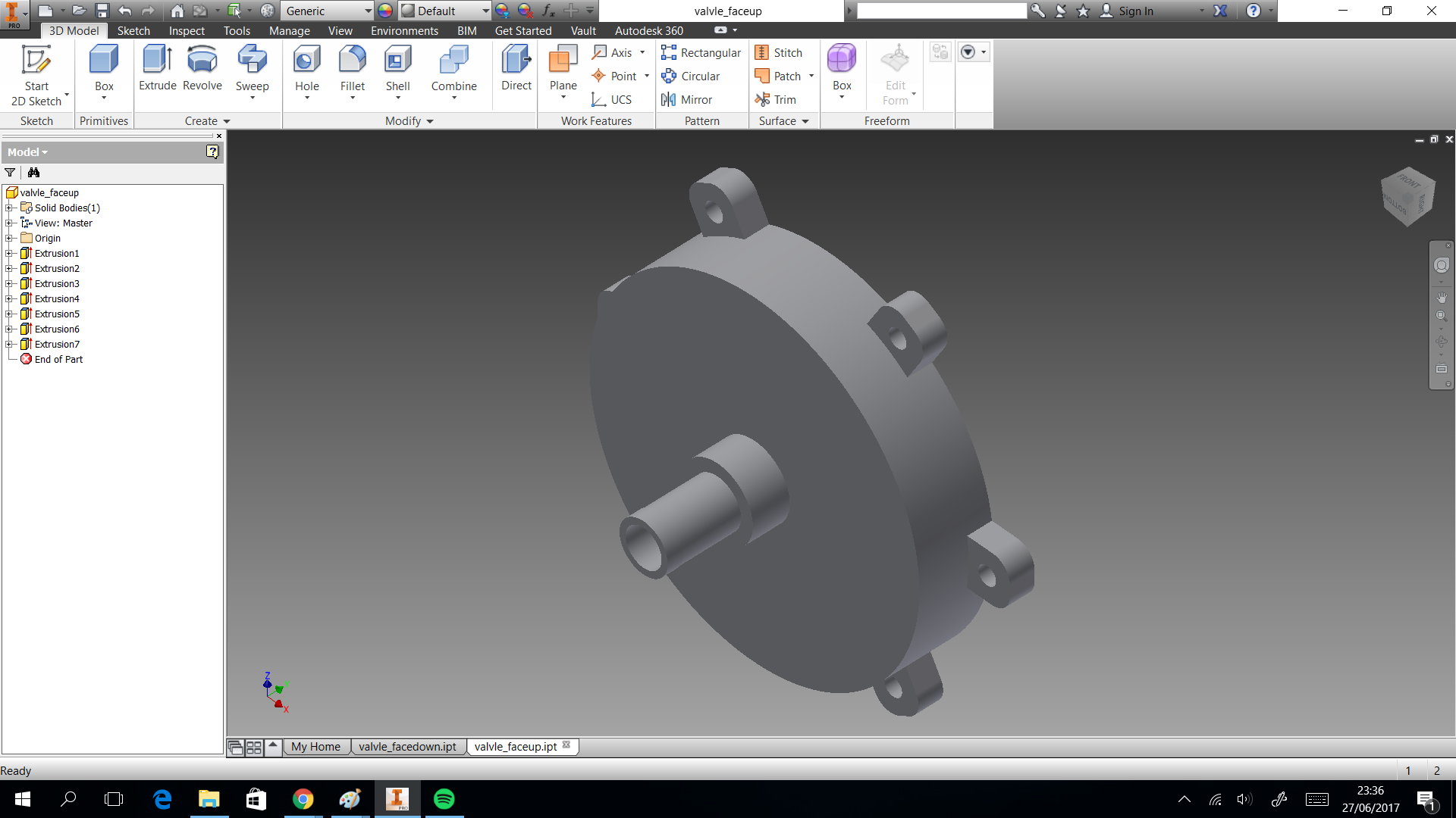
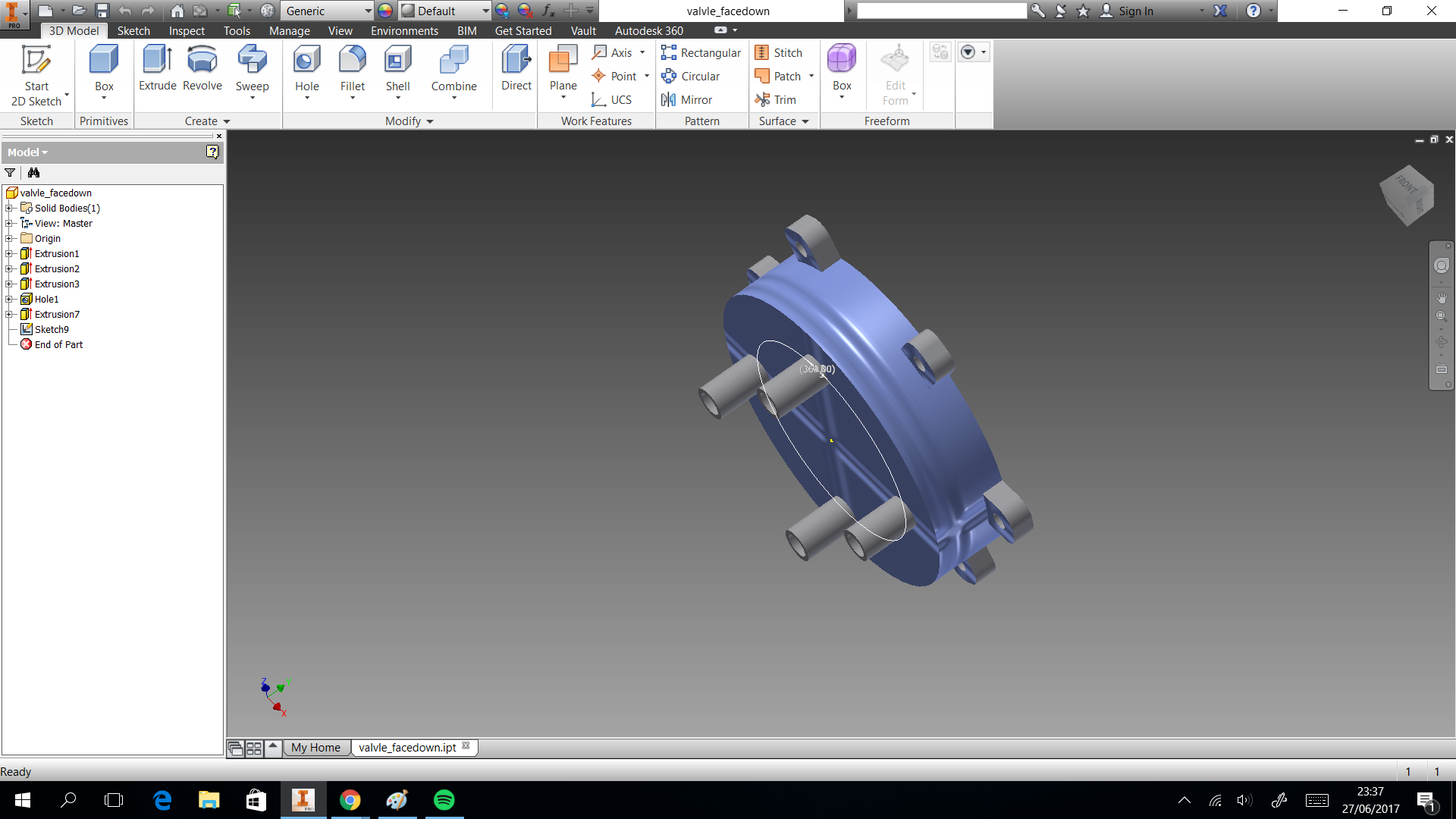
The valve was based on a simple idea of cow udder, which has more than two udders. But we considered a single flow input and multiple flow output. In the 3D printing the elements sent with 60% fill inside, this measure took to not filter water. If only joint the elements with nuts, the valve will filter water. So we cut foami with the form of valve, it puts in the middle of two elements to press. You can donwload the CAD files
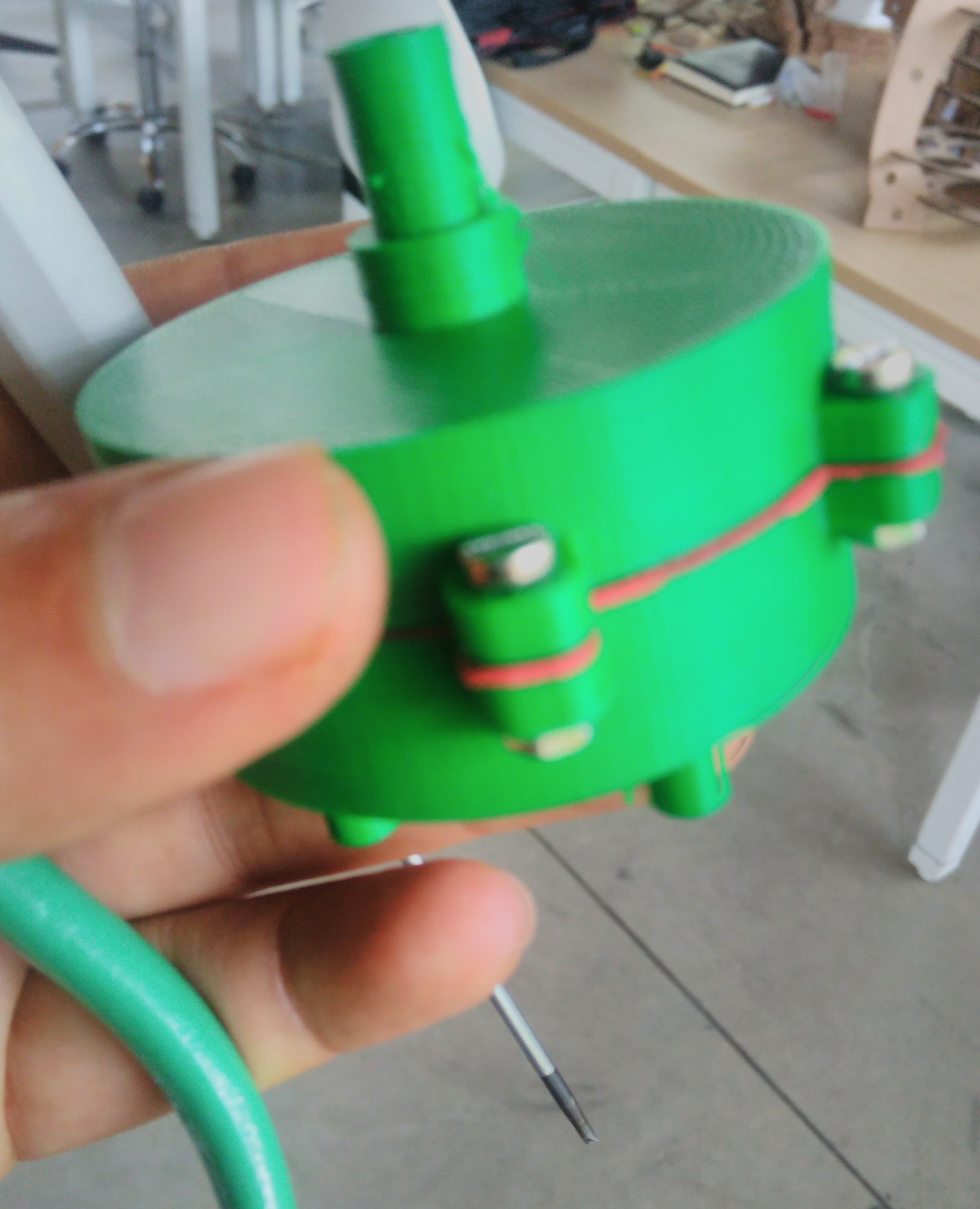
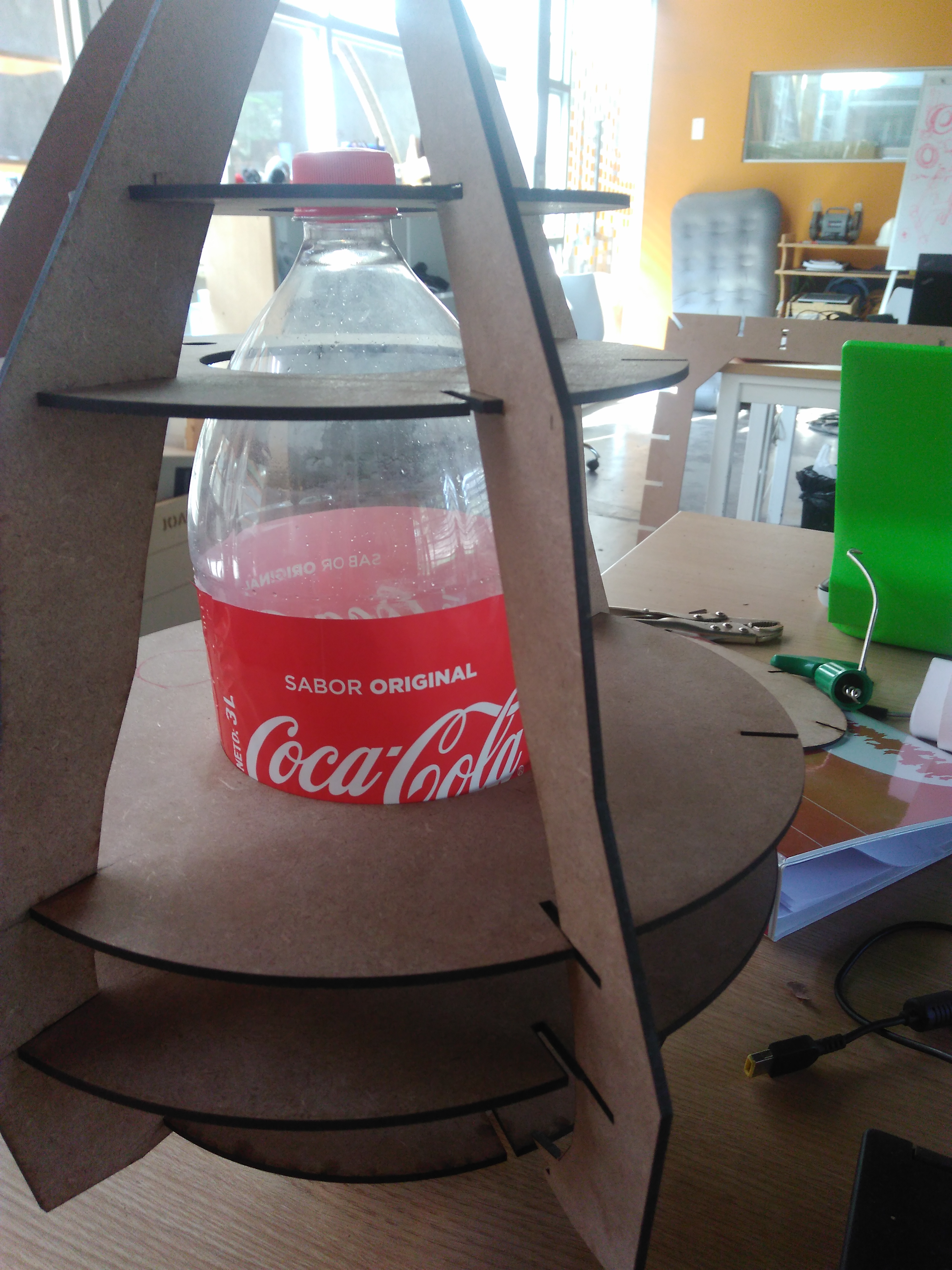
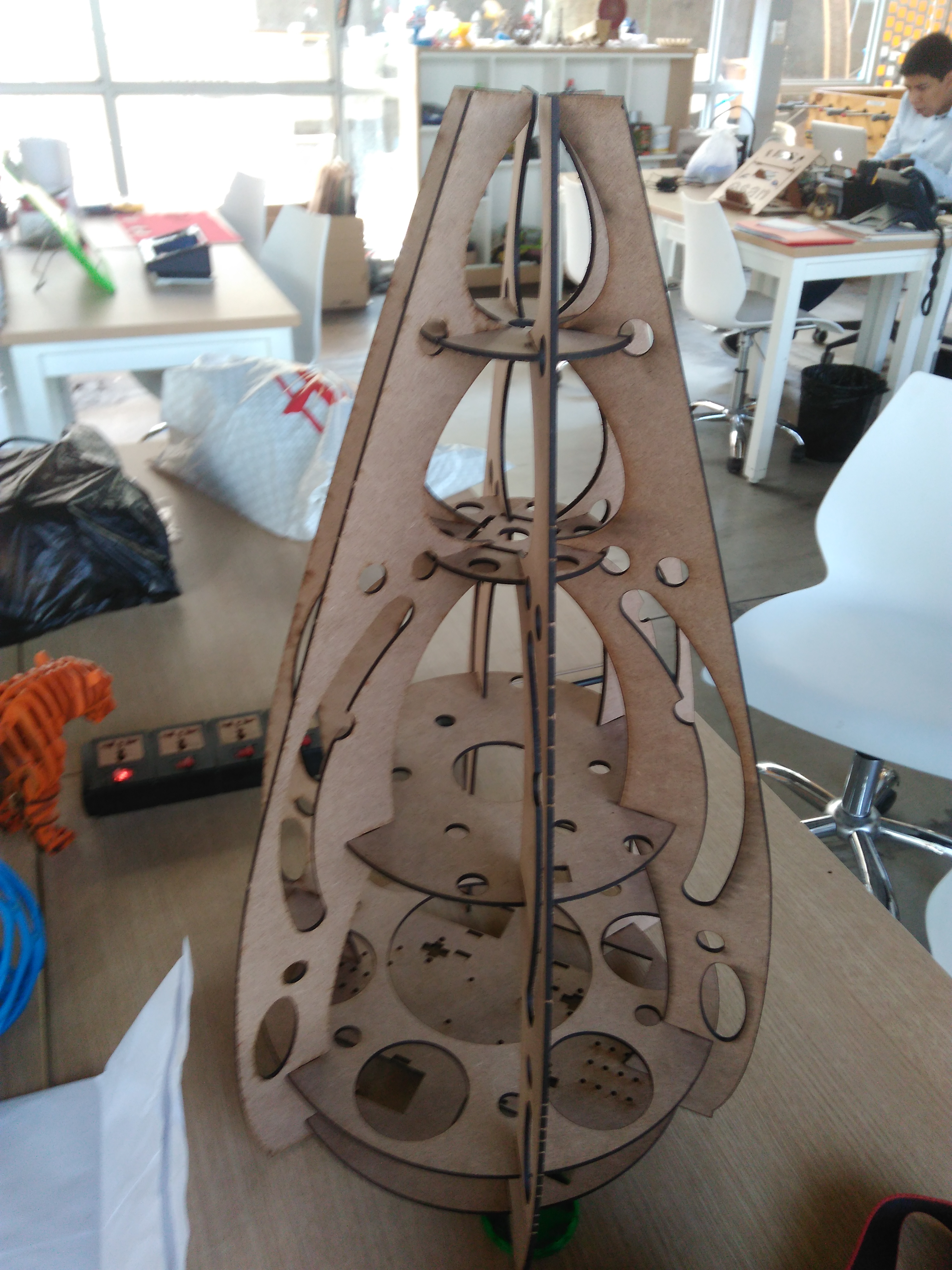
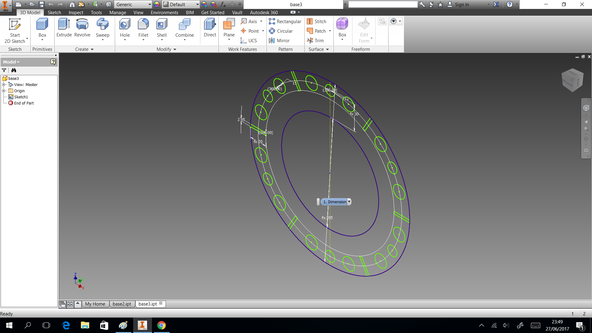
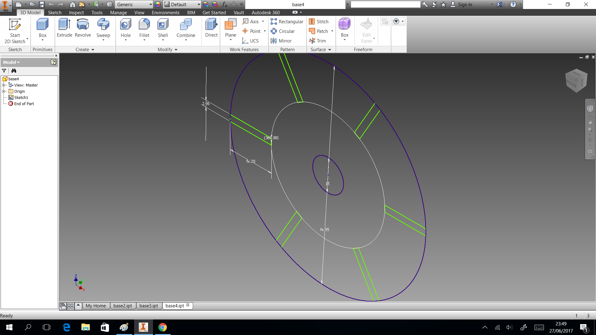
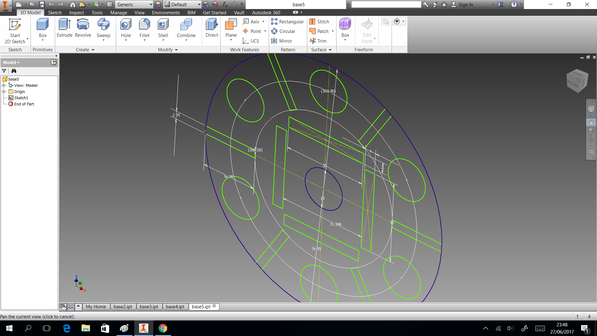
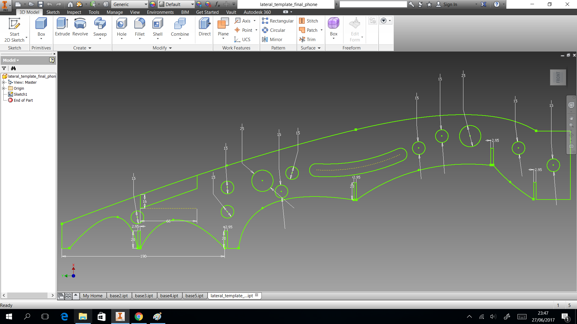
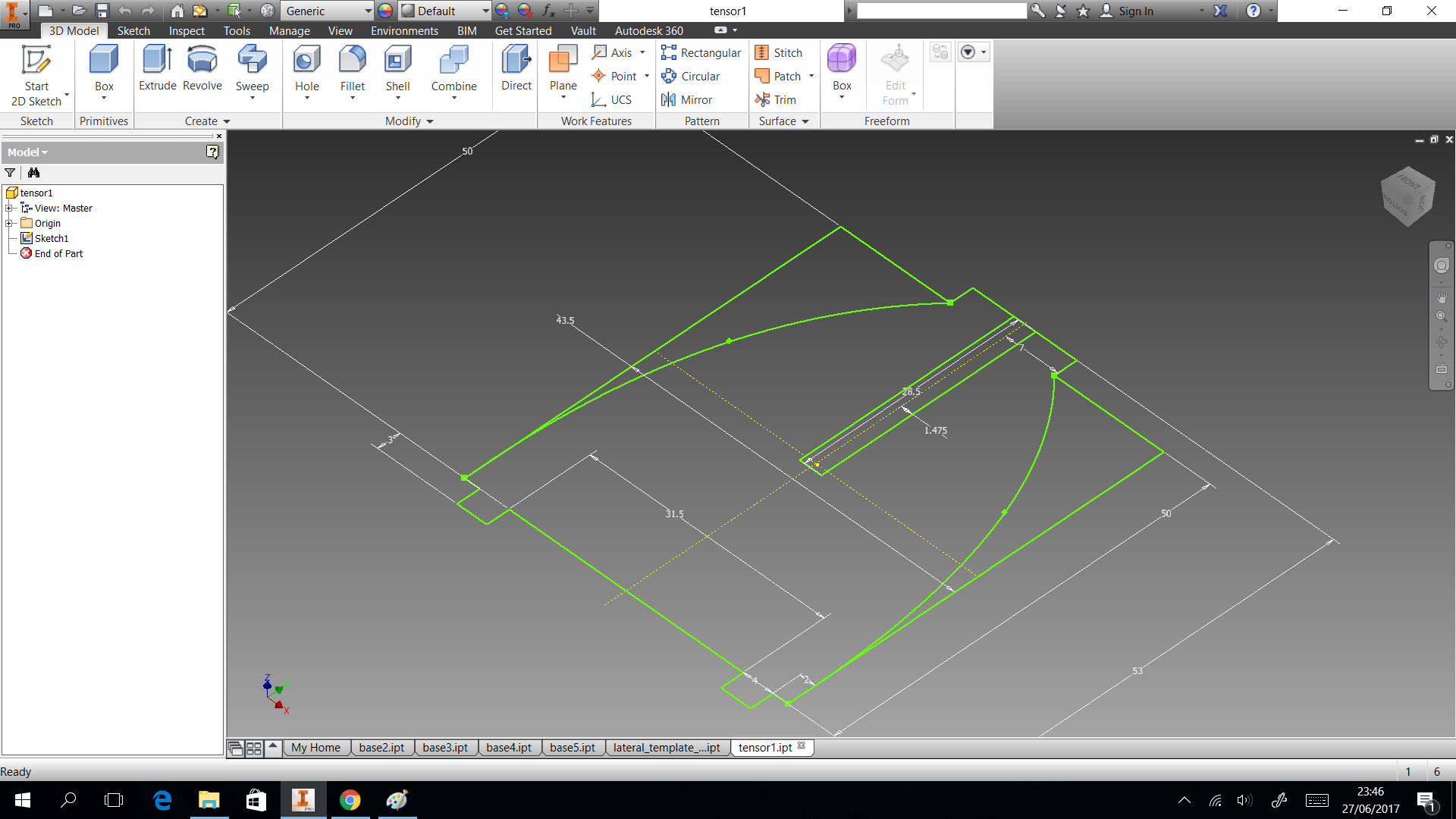
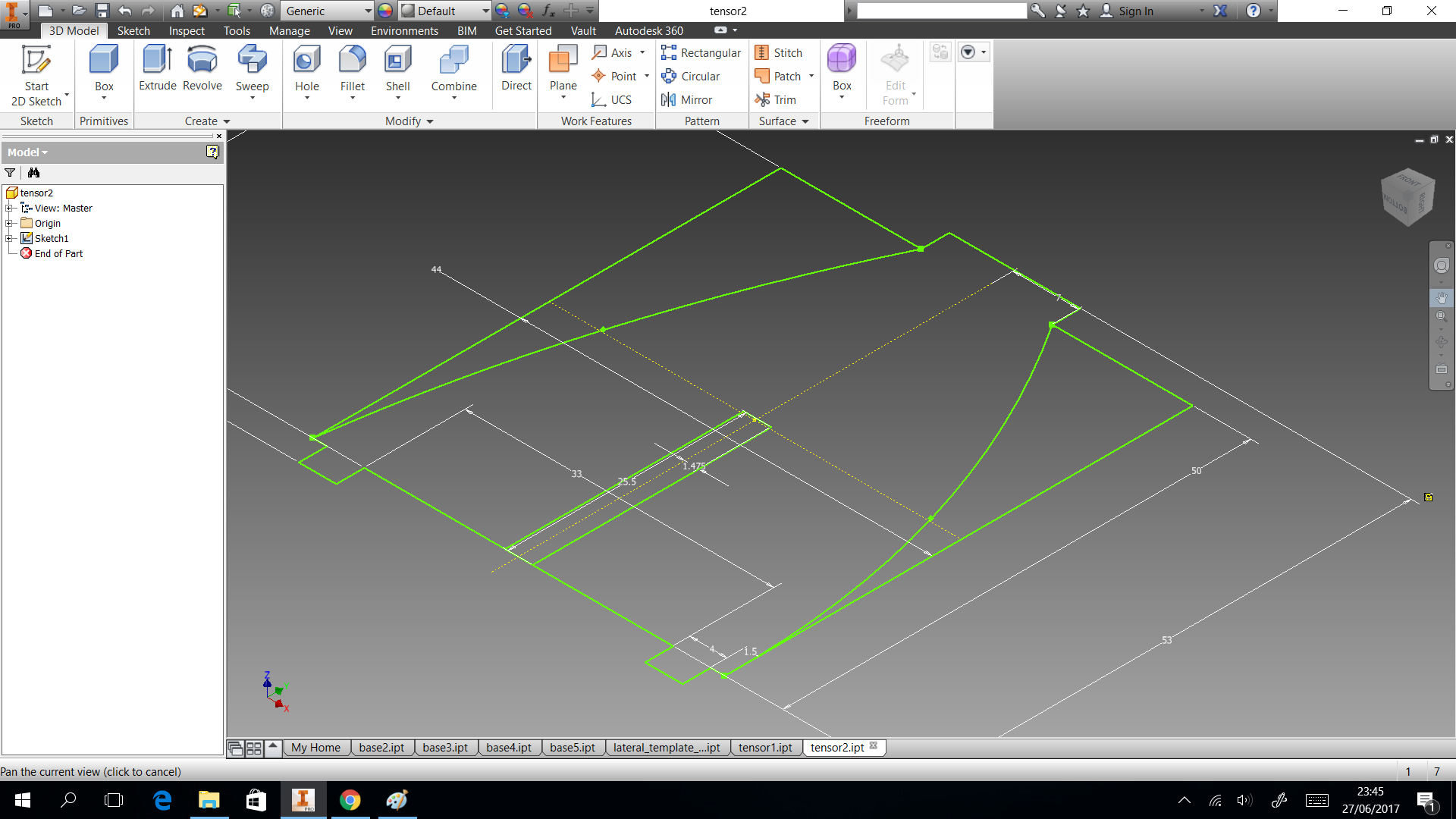
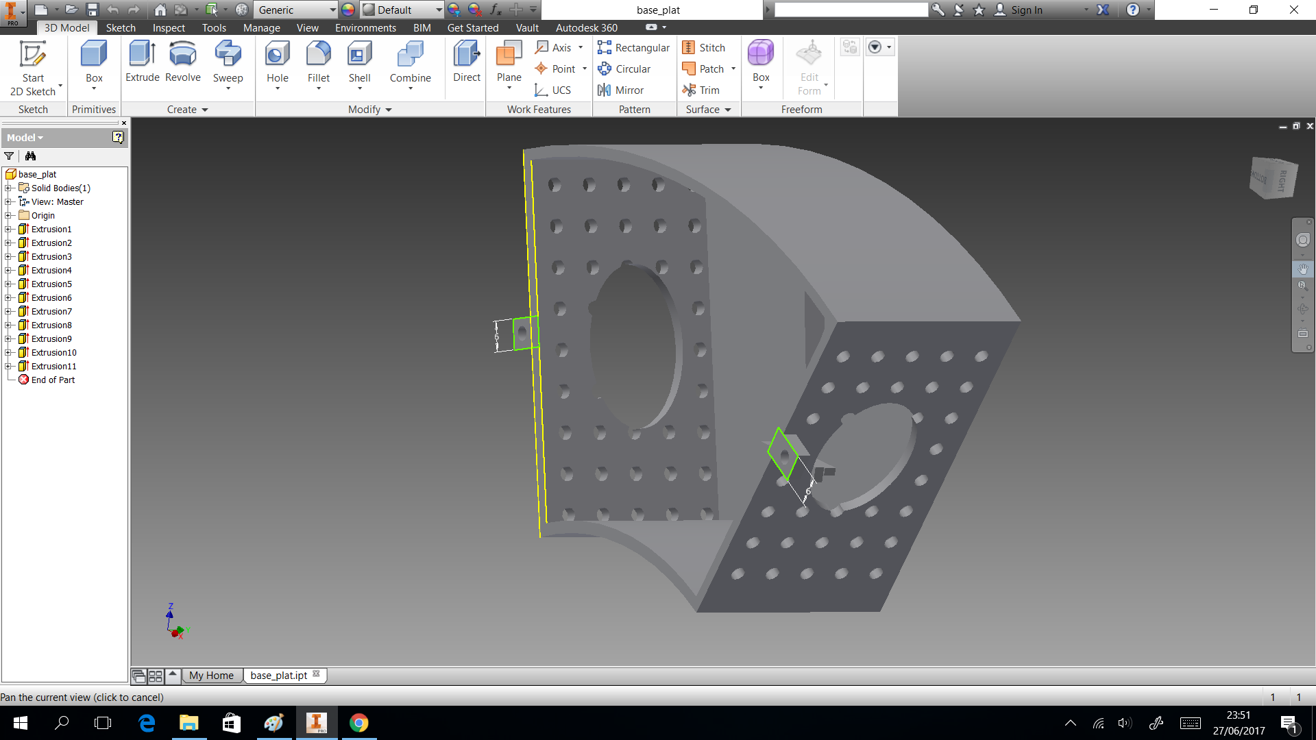
My structure is cool in shape but have limitation as space to put circuit. So I considered only dispensing four glasses and two of them, they will use the space to put a box which close circuits. This design shows in the next images and can download the CAD files
Electronics
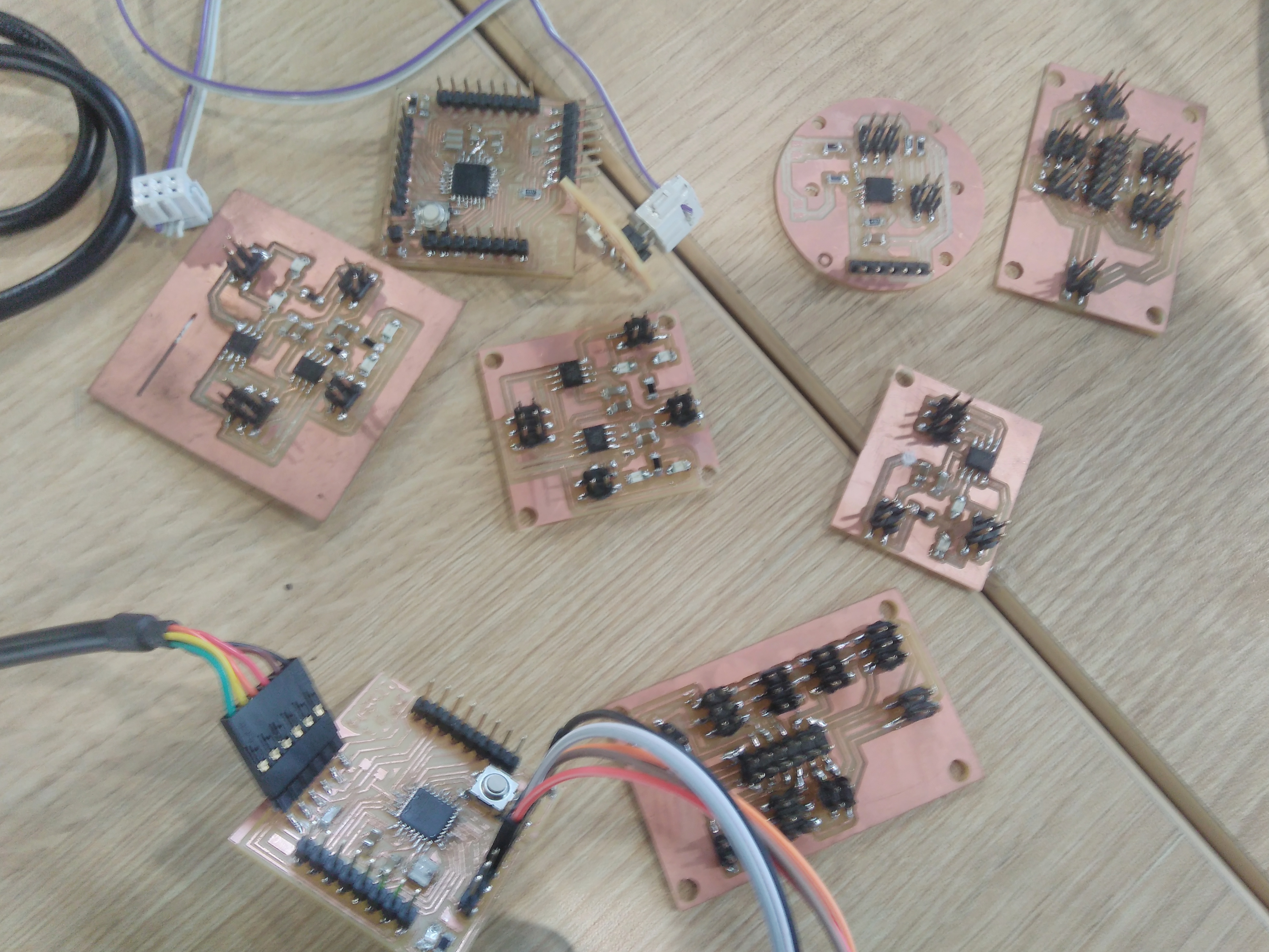
In this section we describe electronics PCB that machine uses. The elements have made IR sensor, H-bridge single,
and boards expansion. Additionally, we produced a boad which has ATMega328p as microcontroller
. It can connect five IR sensors, each one will has 2x3 pin header which two rows are power supply(Vcc and GND) and
digital output.This board has a pin header 2x2 to connect h-bridge with power supply. Also, it has connected tree
pins(13,12,1) with 2x3 headers which can connect with other fabduino through a pin and two pins to interact with
leds.
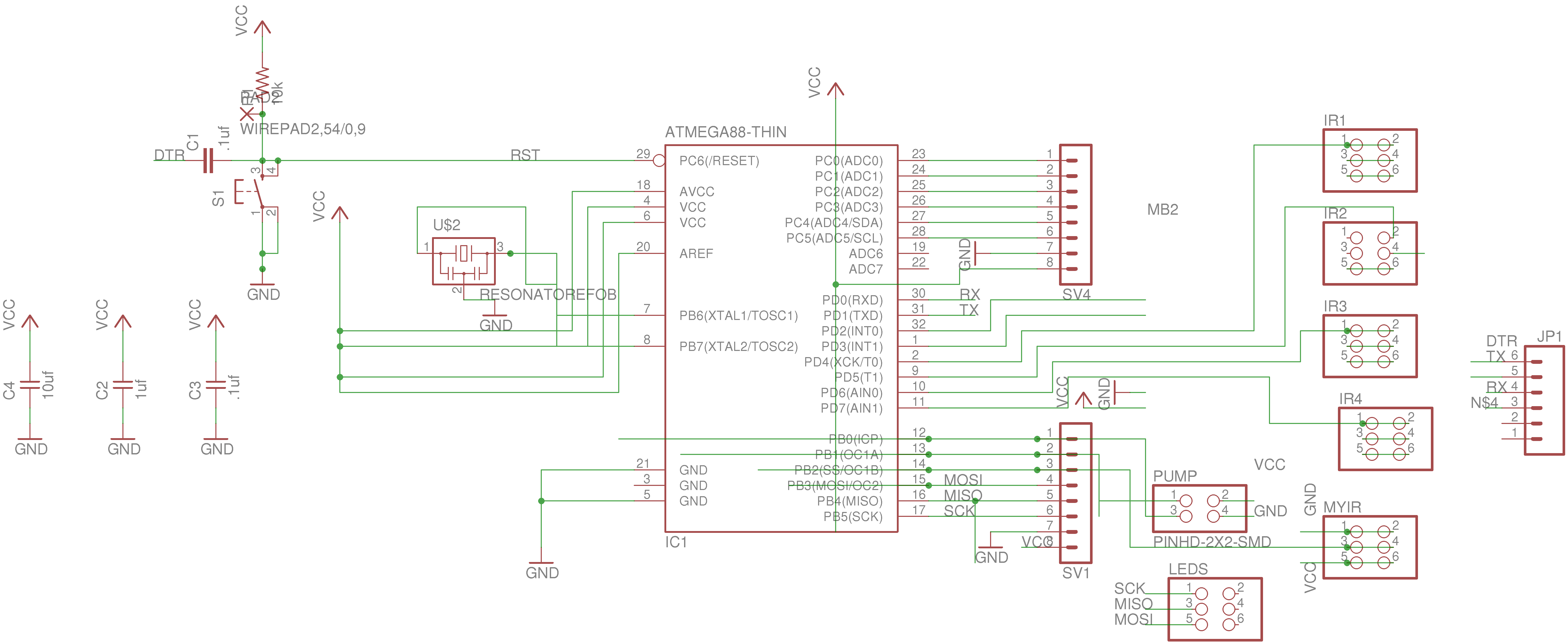
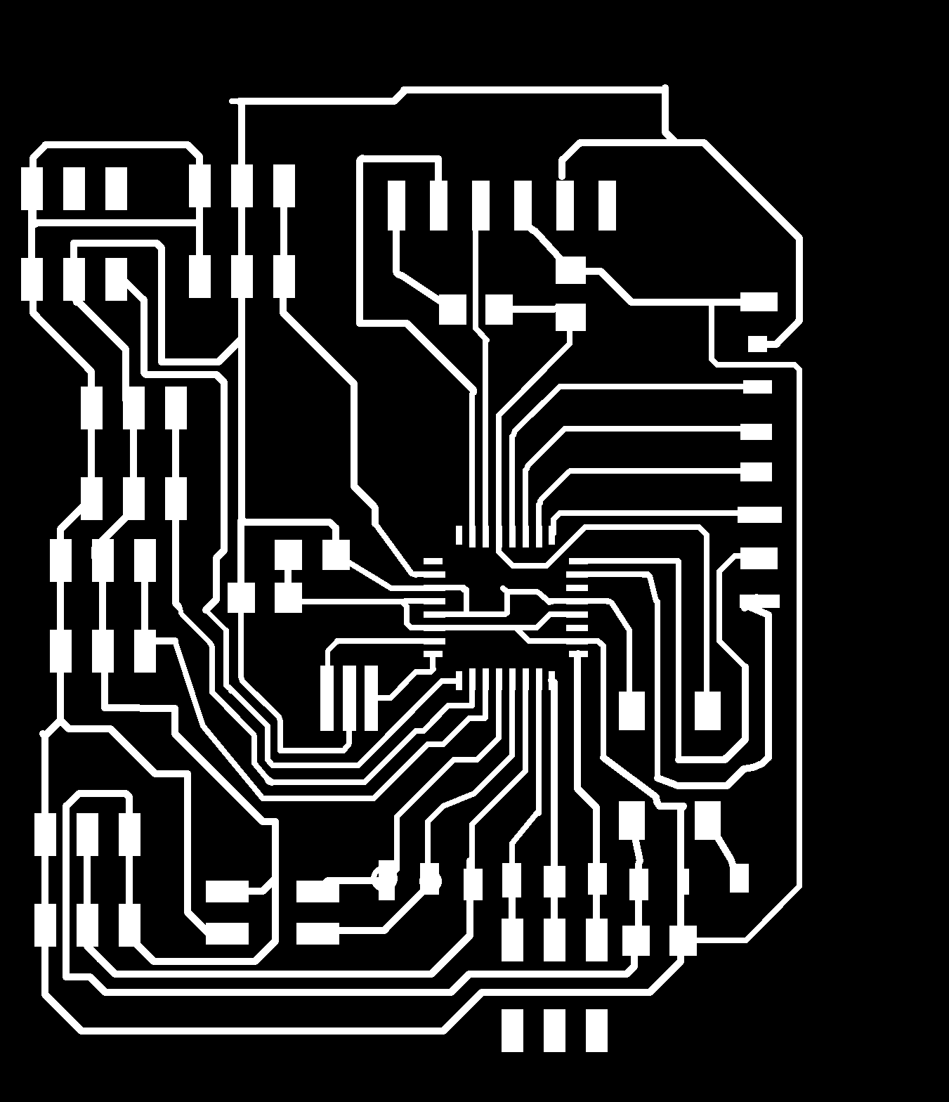
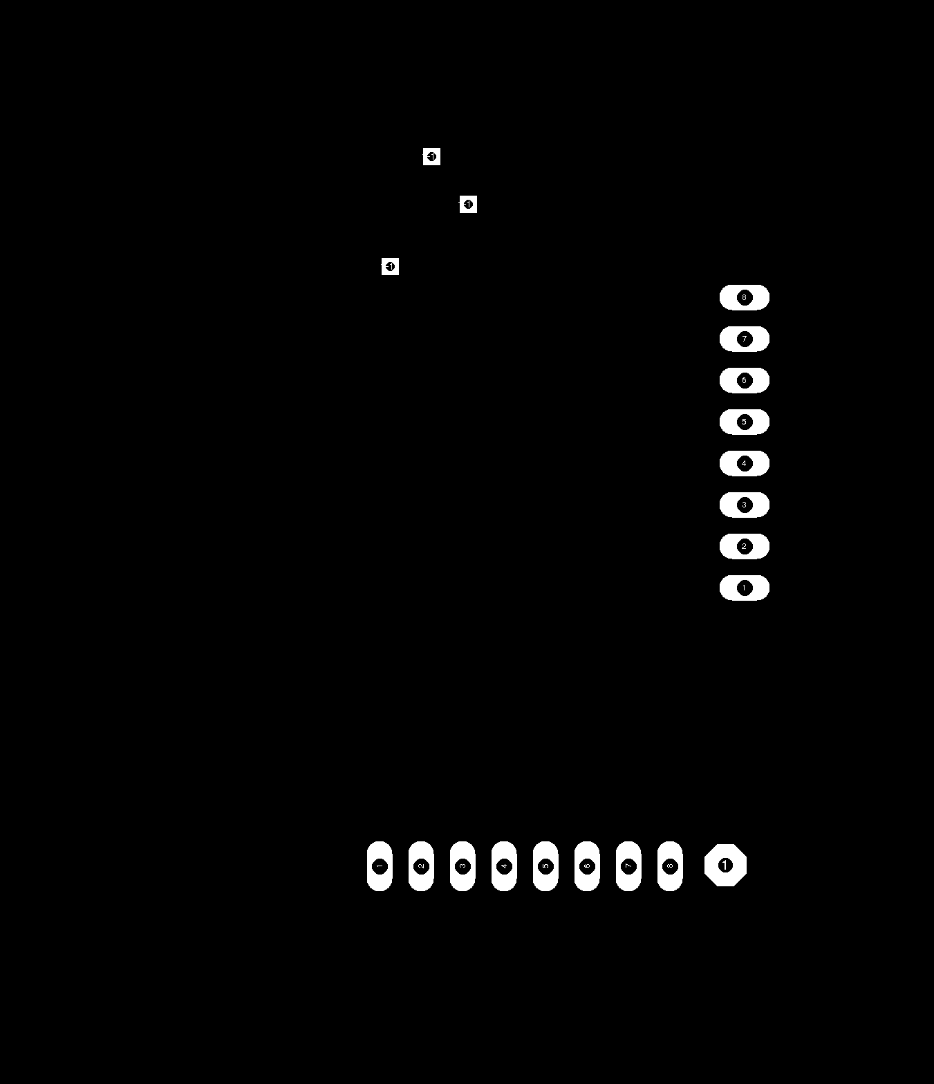
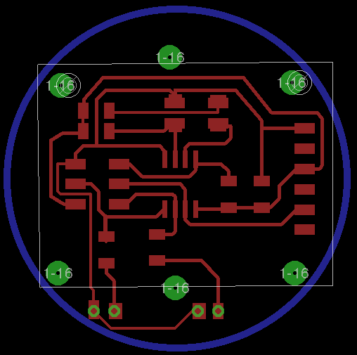
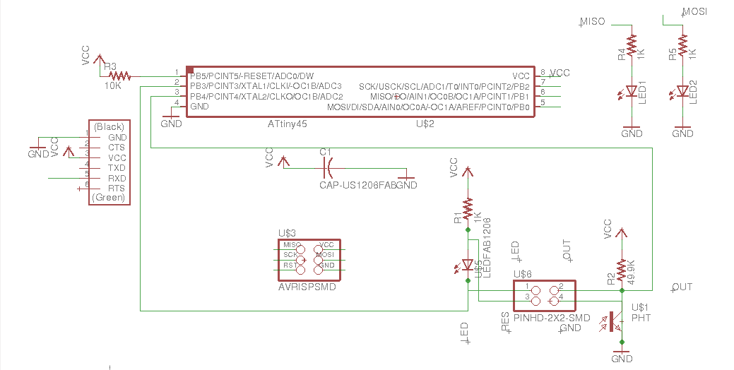
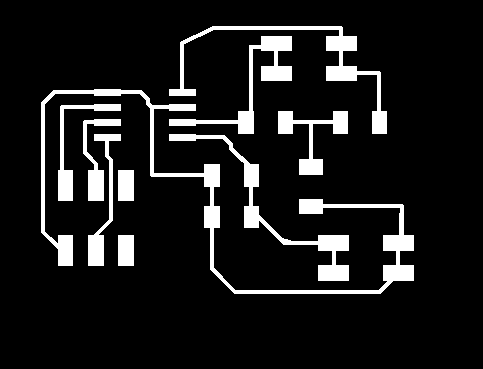
The image belong here represents the schematic electronic of my board. In the right side shows all layout PCB. These designs based on Fabduino 0.2v. So we program this board
with same Fabduino parameters on Arduino IDE:
- Board: Arduino Pro and pro-mini
- Processor: ATmega328( 3.3V 8Mhz)
- Programmer: AVRisp2
You can download the eagle files here
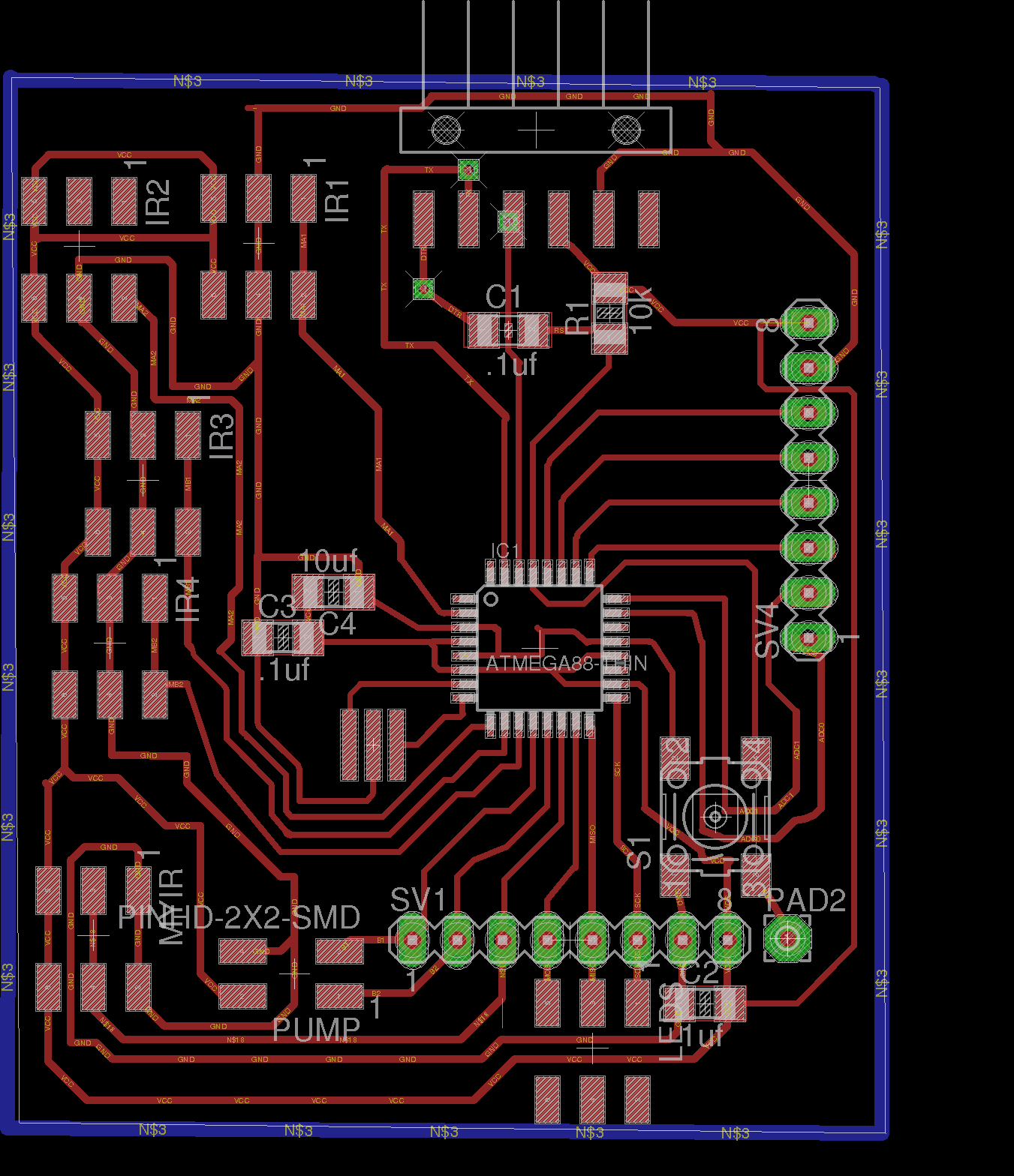
Traces
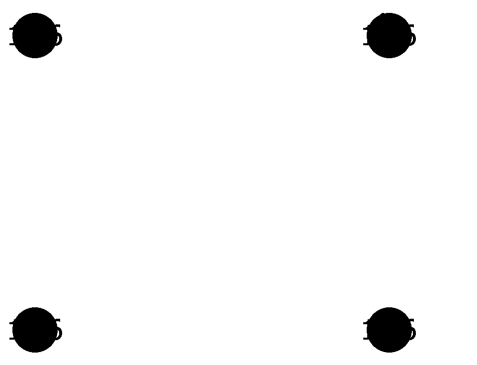
Outline

Holes
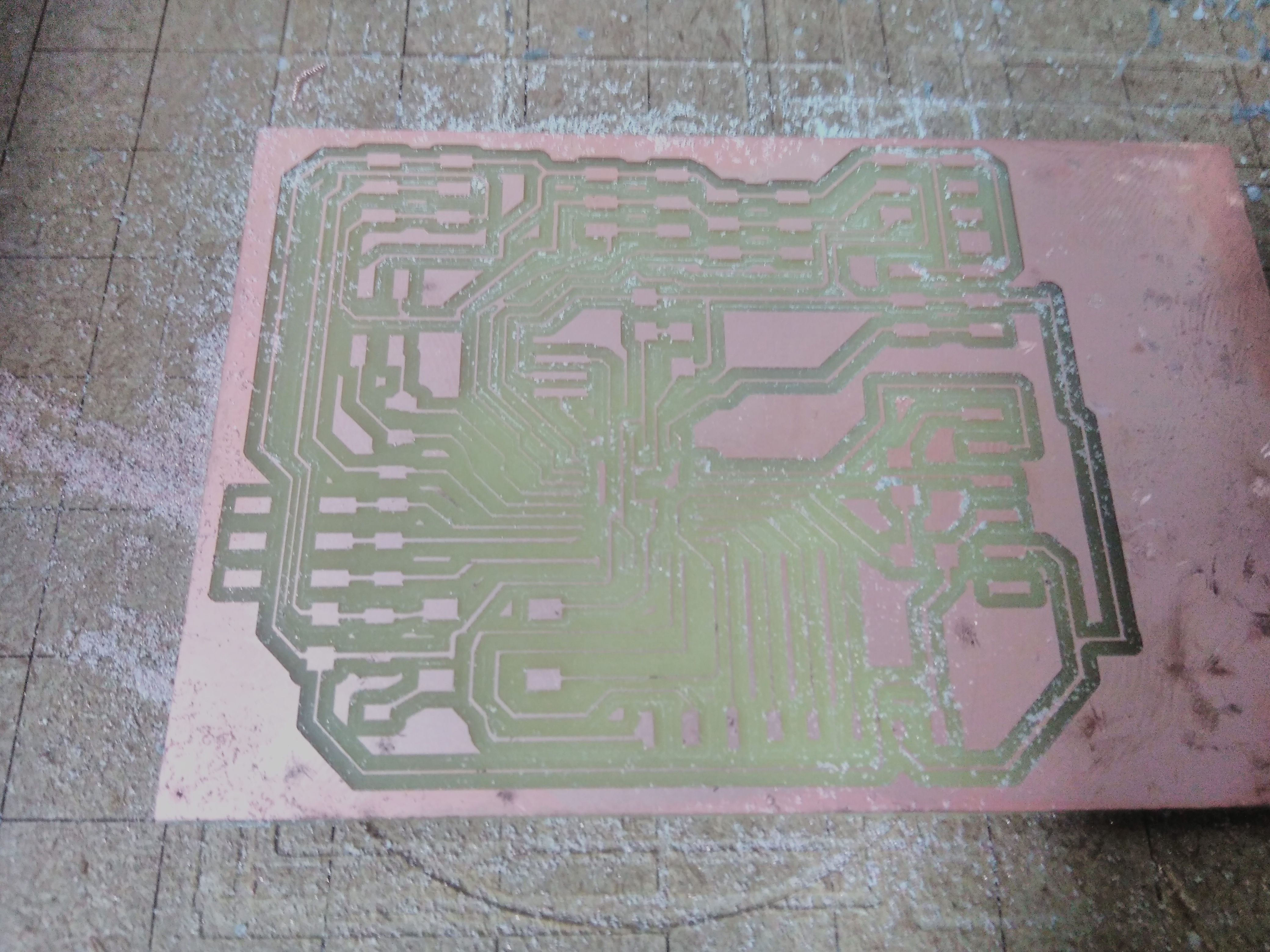
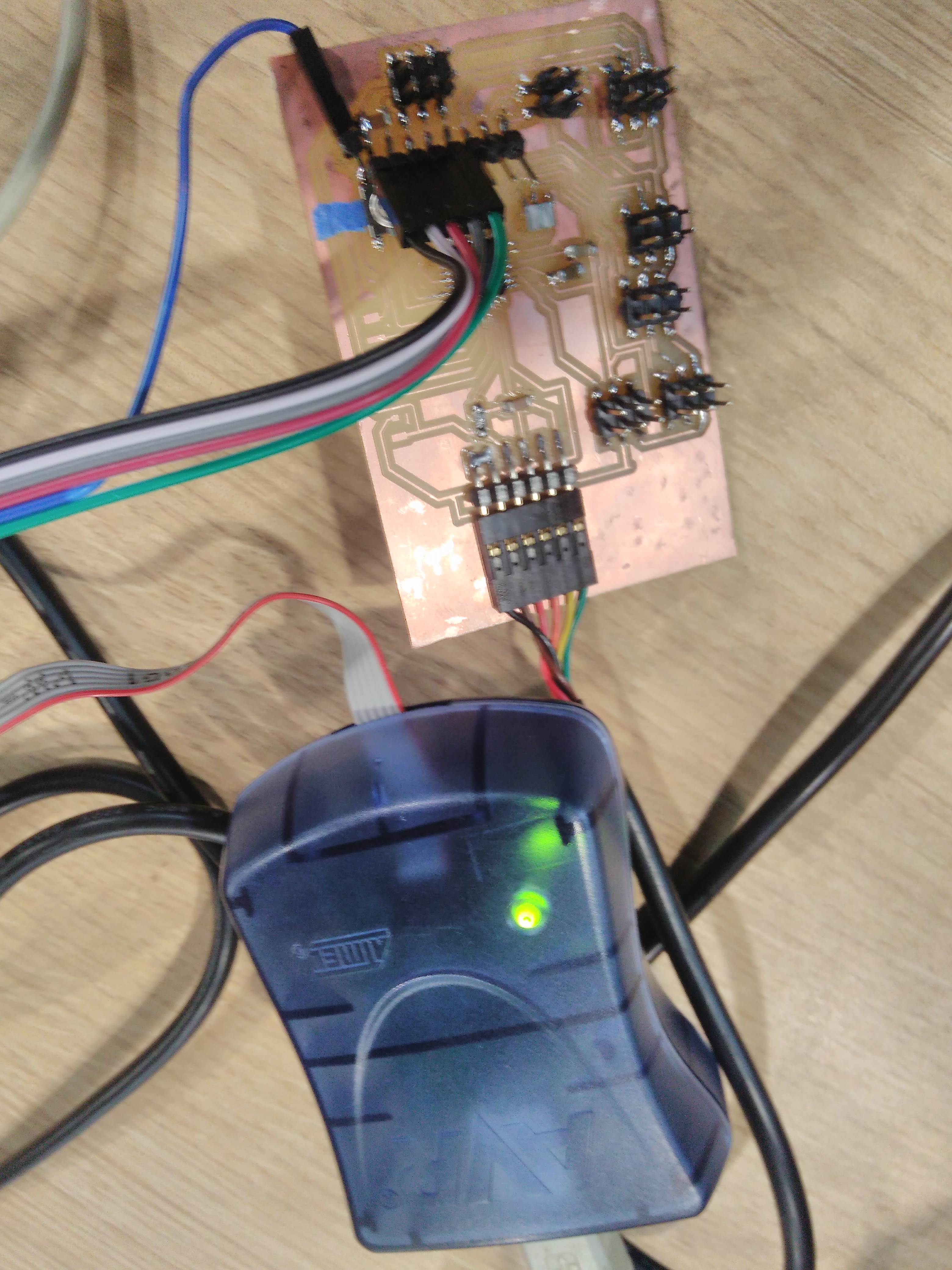
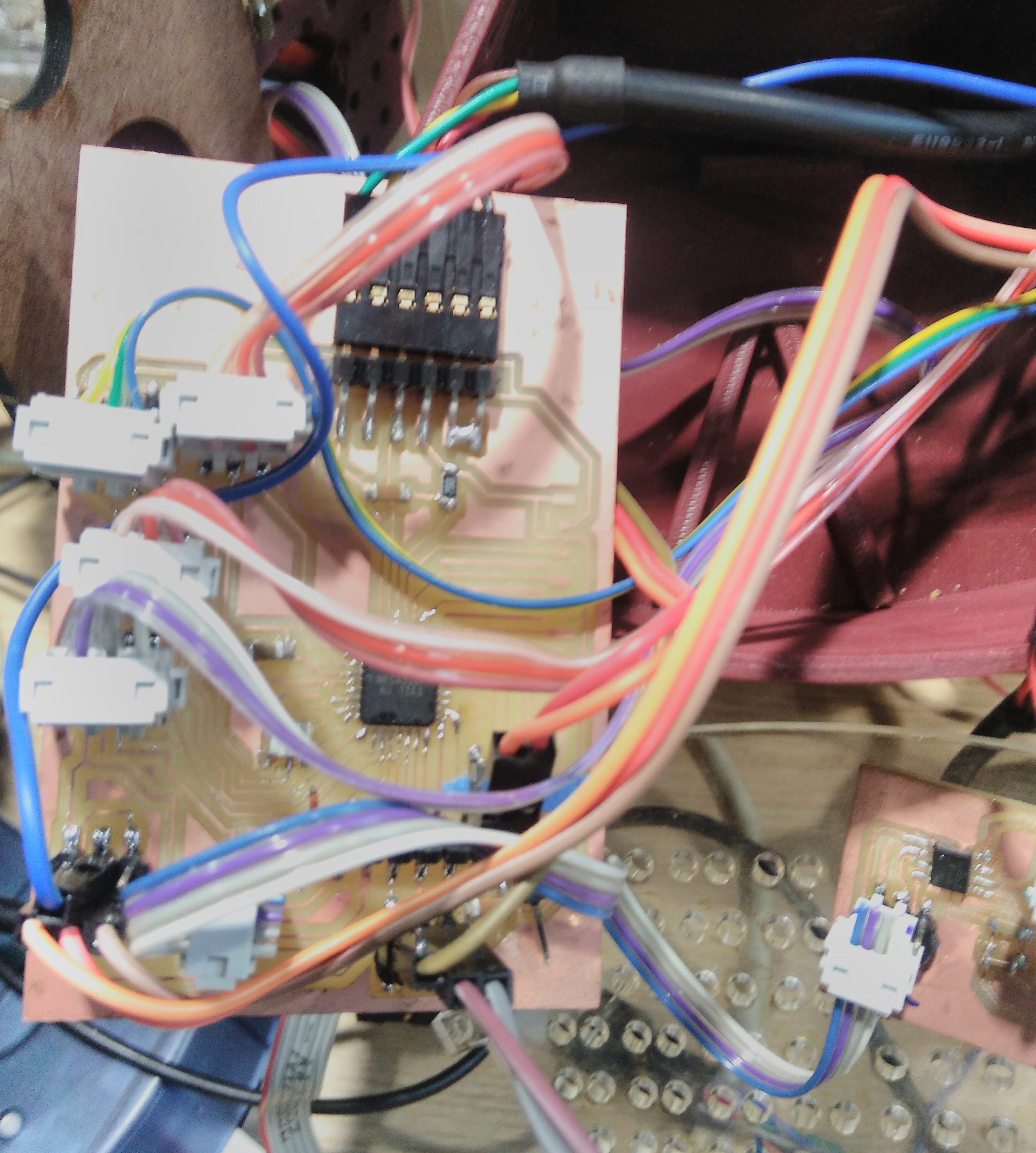
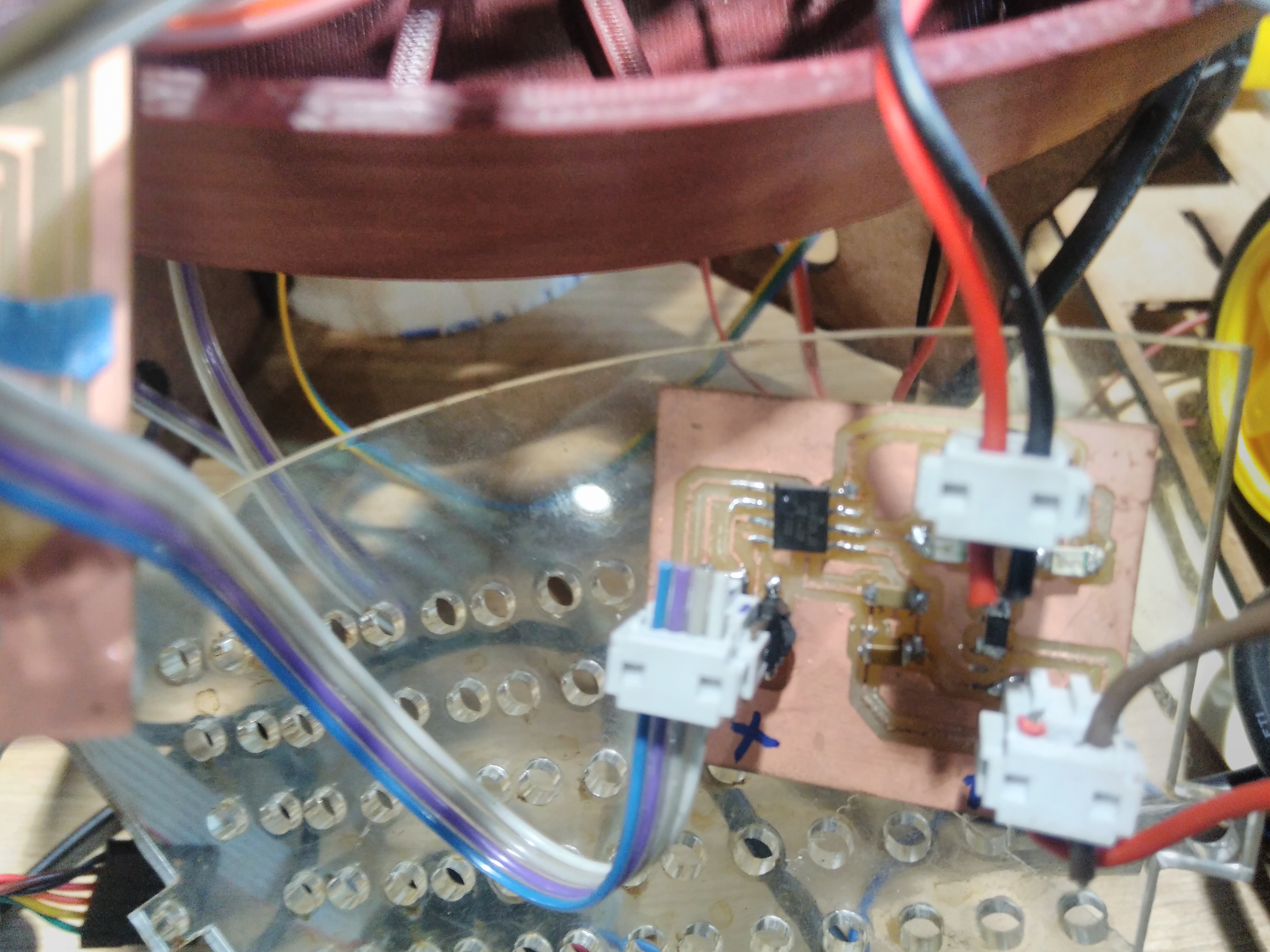
Our board after milling the PCB.
Soldering ATMega328p in the board.
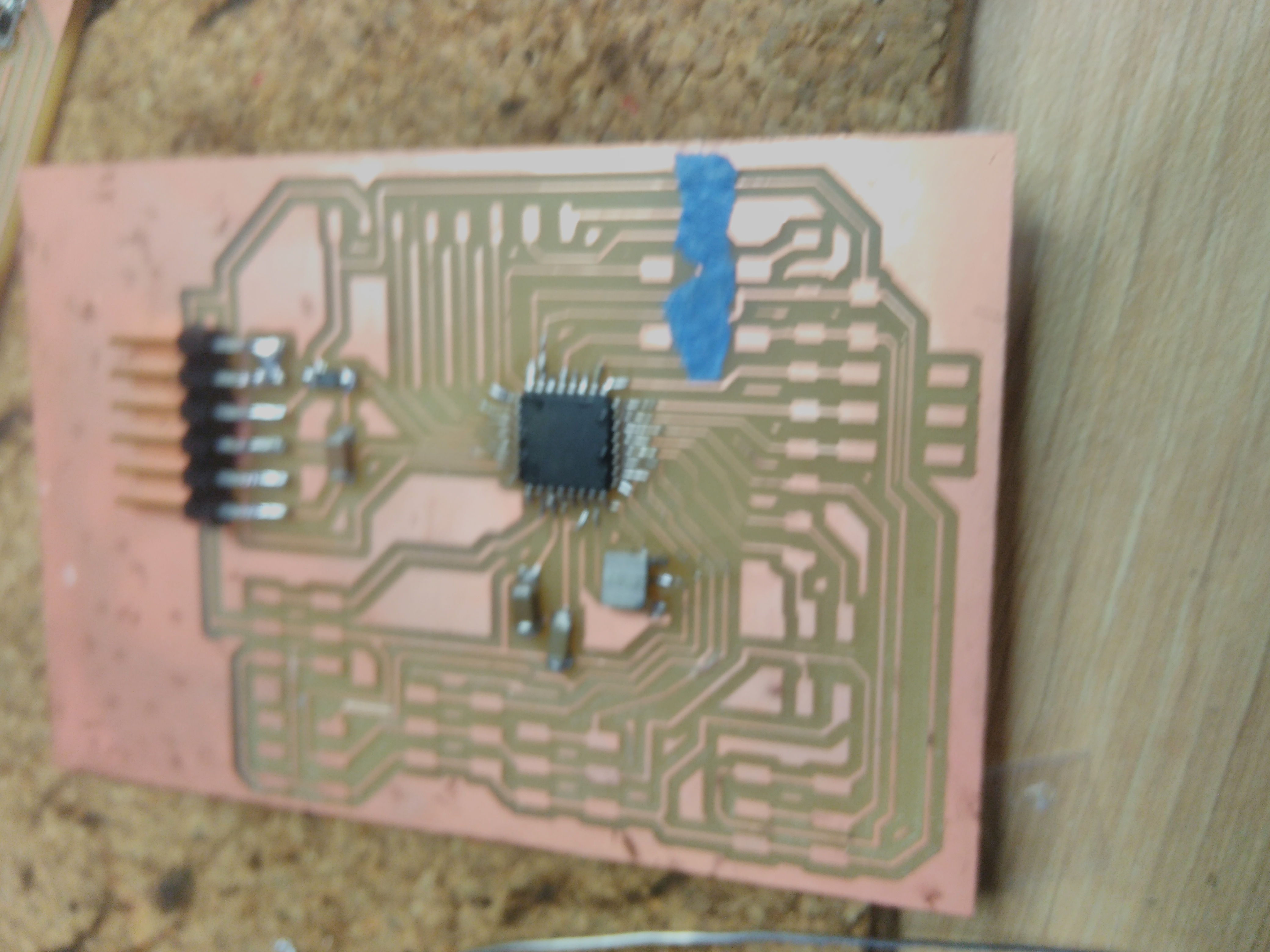
Finally, we tested our board with AVRisp2 to burn bootloader and upload new sketches on Arduino.
My IR sensor fail
We modify the original version of input sensor. The idea was divided in two parts, attiny45 on board, and IR sensor on PCB. You can download the files IR sensor IR module This sensor has special features as minimun distance detection less than 5 centimeters , angle reflection with a few degrees of range, and serial communication. These proporties are impossible to change except the last one. The first ones need to change the electronic components. If the serial communication change, we will get 0 or 1 when the object is near it. The new outputs are like the IR-sensor SKU072960 but we can not regulate distance to detect object in our sensor. We decided this way of sensor because our fabduino will busy all serial communications. Also, the sensing reads in one pin.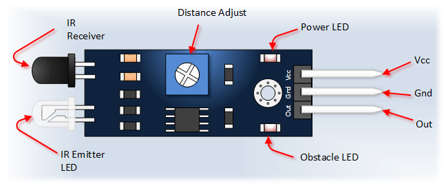 To complete this idea we modified the source code, the original program sends four frames where two firsts represent ADC measure of led off.
The two last are the same kind of measure when the led on. The program in python from the lecture in this week shows how we can calculate the difference, so
we did the same conversion to analyze with binary threshold function.
The next code is the adaption from original source from input assigment.
This circuit has some problems
to upload the code, but we could burn the program one time.
Therefore, we decided to use a commercial IR instead our IR.
To complete this idea we modified the source code, the original program sends four frames where two firsts represent ADC measure of led off.
The two last are the same kind of measure when the led on. The program in python from the lecture in this week shows how we can calculate the difference, so
we did the same conversion to analyze with binary threshold function.
The next code is the adaption from original source from input assigment.
This circuit has some problems
to upload the code, but we could burn the program one time.
Therefore, we decided to use a commercial IR instead our IR.
int main(void) {
 // main
 static unsigned char count;
 static uint16_t on,off;
 float fliter = 0, eps= 0.9 , amp=25.0;
 // set clock divider to /1
 CLKPR = (1 << CLKPCE);
 CLKPR = (0 << CLKPS3) | (0 << CLKPS2) | (0 << CLKPS1) | (0 << CLKPS0)
 // initialize output pins
 set(serial_port, serial_pin_out);
 output(serial_direction, serial_pin_out);
 set(led_port, led_pin);
 output(led_direction, led_pin);
 // init A/D
 ADMUX = (0 << REFS2) | (0 << REFS1) | (0 << REFS0) // Vcc ref
		| (0 << ADLAR) // right adjust
		| (0 << MUX3) | (0 << MUX2) | (1 << MUX1) | (0 << MUX0); // ADC2
 ADCSRA = (1 << ADEN) // enable
		| (1 << ADPS2) | (1 << ADPS1) | (1 << ADPS0); // prescaler /128
 // main loop
 while (1) {
		// accumulate
		on = 0;
		off = 0;
		for (count = 0; count < nloop; ++count) {
			 // LED off
			 set(led_port, led_pin);
			 // initiate conversion
			 ADCSRA |= (1 << ADSC);
			 // wait for completion
			 while (ADCSRA & (1 << ADSC))
					;
			 // save result
			 off += ADC;
			 // LED on
			 clear(led_port, led_pin);
			 // initiate conversion
			 ADCSRA |= (1 << ADSC);
			 // wait for completion
			 while (ADCSRA & (1 << ADSC))
					;
			 // save result
			 on += ADC;
			 }

on = on/nloop;
off = off/nloop;
//conversion
filter =  eps*amp*(float(on-off))
if(filter > 350)
{
	put_char(&serial_port, serial_pin_out, 255);
}
else
{
	put_char(&serial_port, serial_pin_out, 0);
}
char_delay();
		}
 }
extension IR
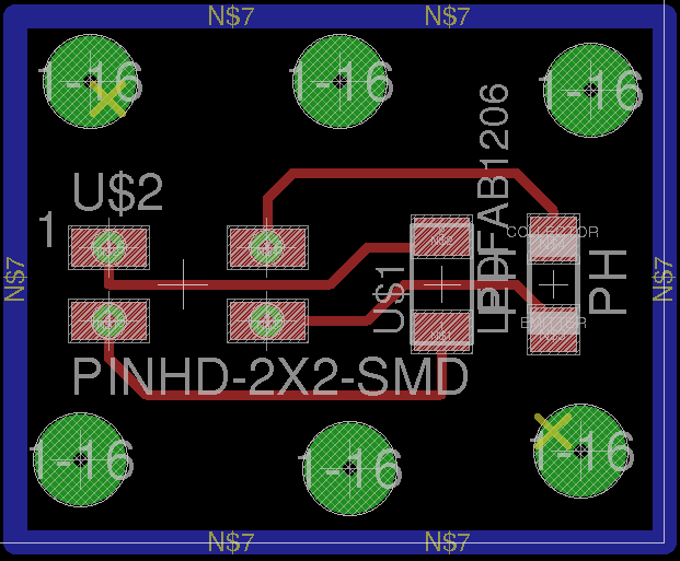
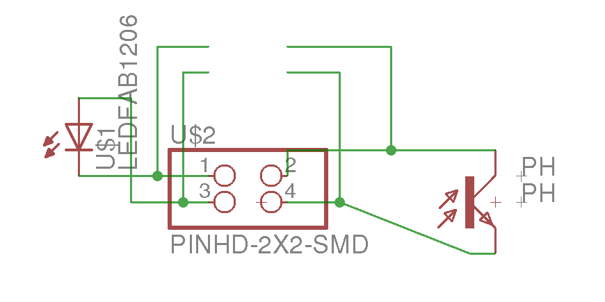
IR board
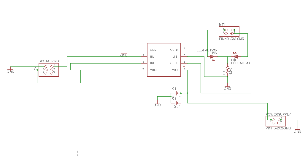
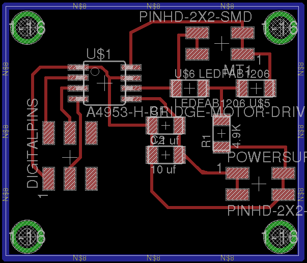
H-Bridge
Based on output device DC motor from fabacademy lecture. I have designed a single H-bridge board which will use to active pump water for distribution. The eagle fileshere
.

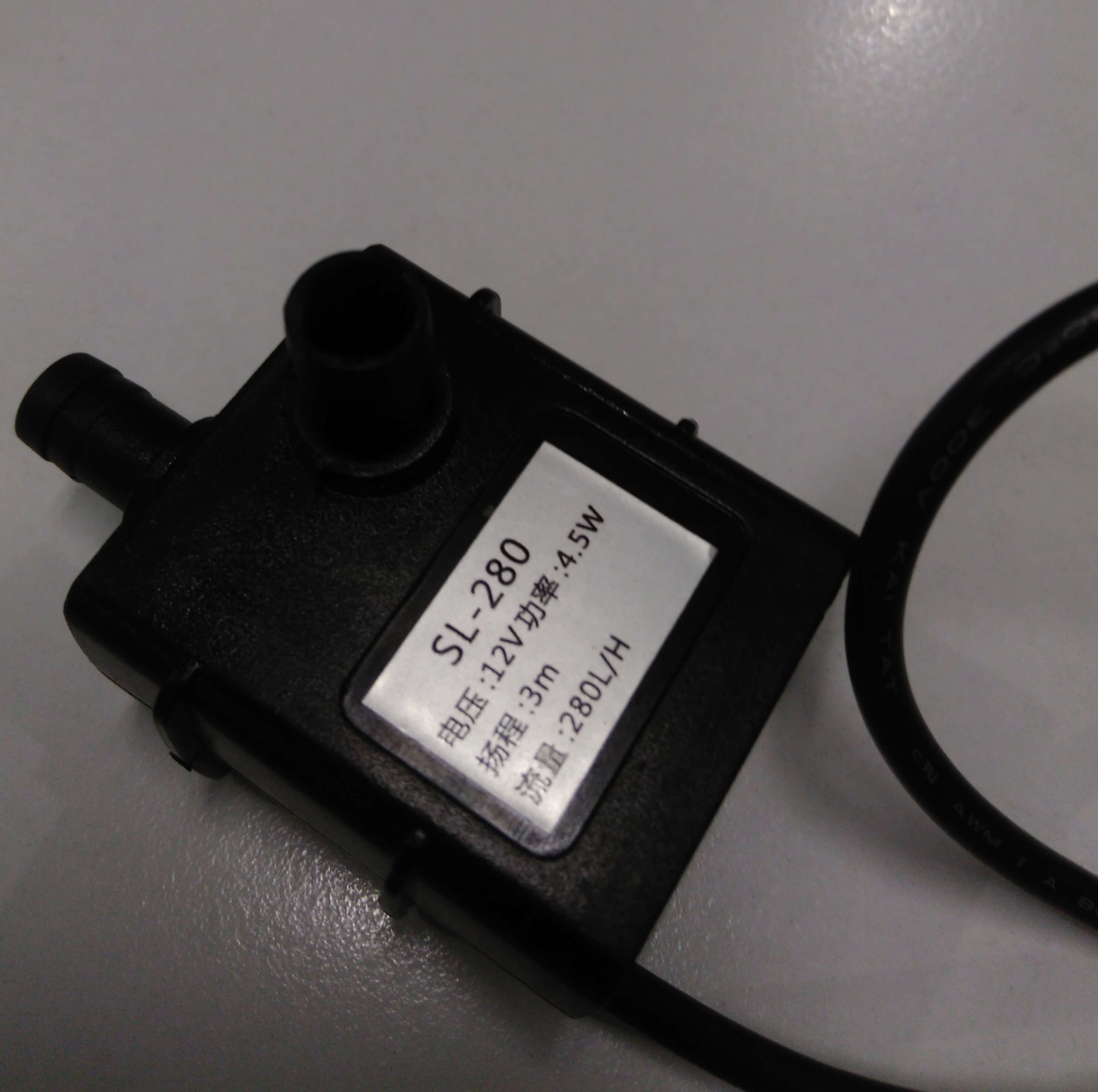
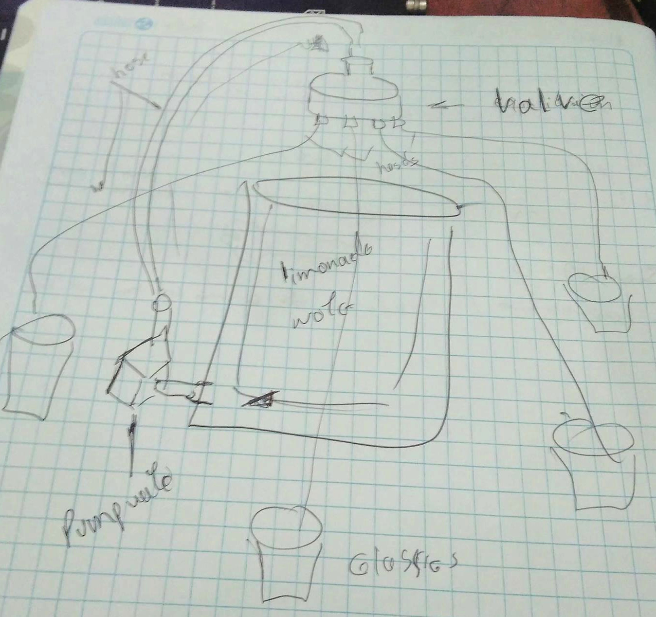
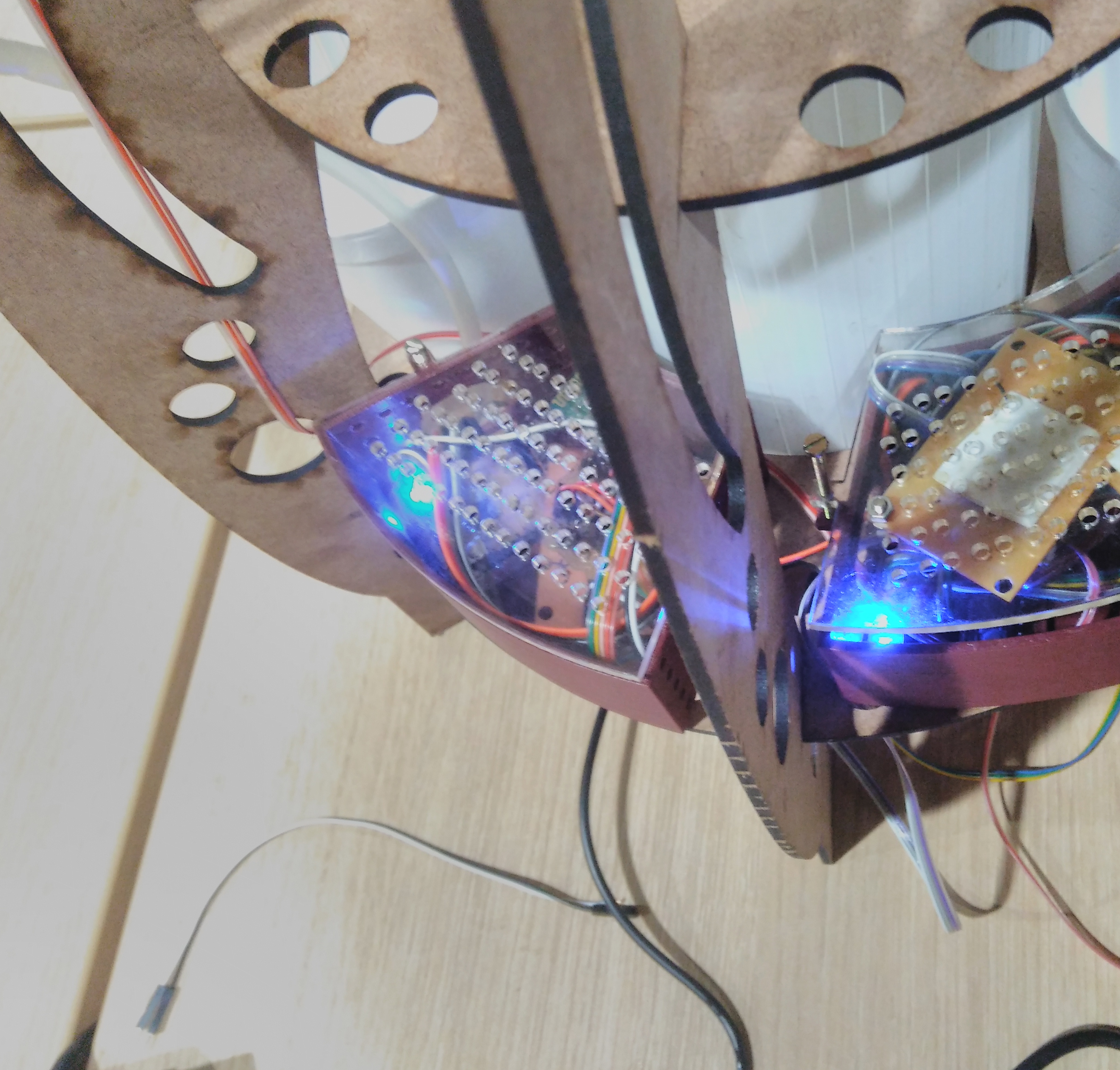
The pump water
I have chosen a pump water SL-180 which has features as voltage 12V, flow 180L/H, lift 1 meters, outlet diameter 8mm. Mini brushless DC pump, almost no noise. Suitable for small landscape, rockery, bonsai, fountains, small fish on the table. If we put the pump water inside the JAR to distribute the water it will like dirty. So I decided to take advantage of gravity.The image in the right side we shows how to will operate the pump water. When it will power on the water flow in hose to input valve. It can distribute to multiple outputs, for each one has hose to connect with a glass. A normal distribution water depends of the positions of valve.
Programming
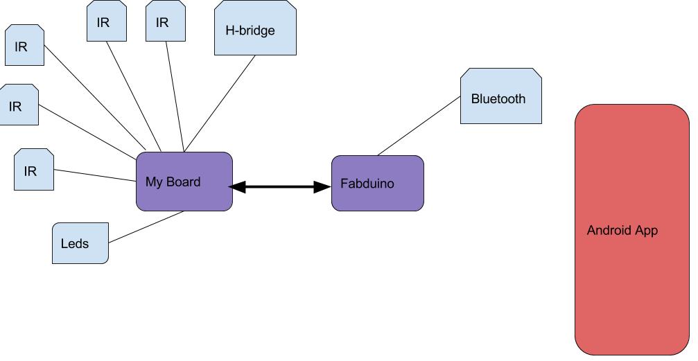
The right image shows the hardware architecture which help to program the machine. The first fabduino is connected to expansion board where can plug in IR sensors, leds , H-bridge and one plug in to listen activation digital signal from fabduino 2. It connects to second expansion board plug inbluetooth. The idea is the app connect through bluetooth, and after 15 seconds the machine wait to sense people around it. When programming of this machine has three programs: android app, fabduino1 and fabduino2. The android app is the same that the interface and application programming . In the next subsection detail the source code for fabduino1 and fabduino2.
My board
int re;
int activation;

void setup() {
  // put your setup code here, to run once:
   DDRD = B00001111;
   Serial.begin(9600);

   pinMode(8, OUTPUT);
   pinMode(9, OUTPUT);
   pinMode(10, INPUT);
   pinMode(11, OUTPUT);
   pinMode(12,OUTPUT);
   pinMode(13,OUTPUT);

   digitalWrite(11, LOW);
   digitalWrite(12, LOW);
}

void loop() {
  // put your main code here, to run repeatedly:


   activation = digitalRead(10);
   Serial.println("Activation: ");
   Serial.println(activation);
   digitalWrite(13, activation);

   if(activation == HIGH){
   re = PIND;
   re = re & B11110000;
   Serial.println(re);


   if(re == 0) //when all IR sensore will be activing by people
   {
    Serial.println("machine is activing");
    //Turn on the bomb water
     digitalWrite(8, HIGH);
    digitalWrite(9, LOW);

    //turn on led 11
    digitalWrite(11, HIGH);
    for(int i=0; i < 10; i++){
      //blink the led 12
      digitalWrite(12, HIGH);
      delay(500);
      digitalWrite(12, LOW);
      delay(500);
    }

   //turn of the bomb
    digitalWrite(9,LOW);
   digitalWrite(8, LOW);

   //you can drink  and wait to take the glass  for 10 seconds
   digitalWrite(12, HIGH);
   delay(10000);

   }
   else
   {
    digitalWrite(11, HIGH);
    delay(500);
    digitalWrite(11, LOW);
    delay(500);
   }

   }
   digitalWrite(11, LOW);
   digitalWrite(12, LOW);

}
Fabduino 2
#include <SoftwareSerial.h>
#include "tools.h"

SoftwareSerial BTserial(8, 2); // RX | TX

// Connect the HC-05 TX to Arduino pin 8 RX.
// Connect the HC-05 RX to Arduino pin 2 TX through a voltage divider.
// Connect the HC-05 STATE pin to Arduino pin 3.
char c = ' ';

// BTconnected will = false when not connected and true when connected
boolean BTconnected = false;

// connect the STATE pin to Arduino pin D4
const byte BTpin = 3;

//pin activation
const byte ACTpin = 4;

//pin led activation
const byte led = 13;


void setup() {
  // put your setup code here, to run once:
  pinMode(BTpin, INPUT);
  pinMode(ACTpin, OUTPUT);
  pinMode(led, OUTPUT);
  digitalWrite(13, LOW);

  Serial.begin(9600);
  Serial.println("Fabduino is running");
  Serial.println("Connect bluetooth to android device");
  digitalWrite(ACTpin, LOW);
  // wait until the HC-05 has made a connection
    while (!BTconnected)
    {
      if ( digitalRead(BTpin)==HIGH)  { BTconnected = true;};
    }

    Serial.println("HC-05 is now connected");
    Serial.println("");

    //start the bluetooth module
    BTserial.begin(9600);

}

void loop() {
  // put your main code here, to run repeatedly:
  // Keep reading from the HC-05 and send to Arduino Serial Monitor
    if (BTserial.available())
    {
        c = BTserial.read();
         Serial.write(c);

        if(c == 'A')
        {

          Serial.println("Activate machine");
          digitalWrite(ACTpin, HIGH);
          digitalWrite(led, HIGH);

          delay(18000);
          digitalWrite(ACTpin, LOW);
          digitalWrite(led, LOW);
          //BTserial.write('O');
        }

    }

    // Keep reading from Arduino Serial Monitor input field and send to HC-05
    if (Serial.available())
    {
        c =  Serial.read();
        BTserial.write(c);
    }


}
BOM
The materials to complete this project are:
- (1) bluetooth HC-05
- (2) fabduino
- (1) H-bridge
- (4) IR sensor
- (1) my IR sensor
- (2) expansion board
- (1) FTDI wire
- (1) pump water
- (1) soda bottle of 3 litters
- (5) meter hose of 4mmm diameter
- (2) led 5mm 3v
- (1) 9v dc power supply
- (10) 300x600 mm2 MDF 3mm
- (1) 300x600 mm2 acrylic 4mm
- (1) PLA filament
- (5) meters of ribbon wire
Results

This work is licensed under a Creative CommonsAttribution-NoDerivatives 4.0 International License.