Embedded programming
This homework was composed by two assigments:
Tasks
- Read a microcontroller data sheet
- Program your board to do something, with as many different programming languages and programming environments as possible
Read a microcontroller
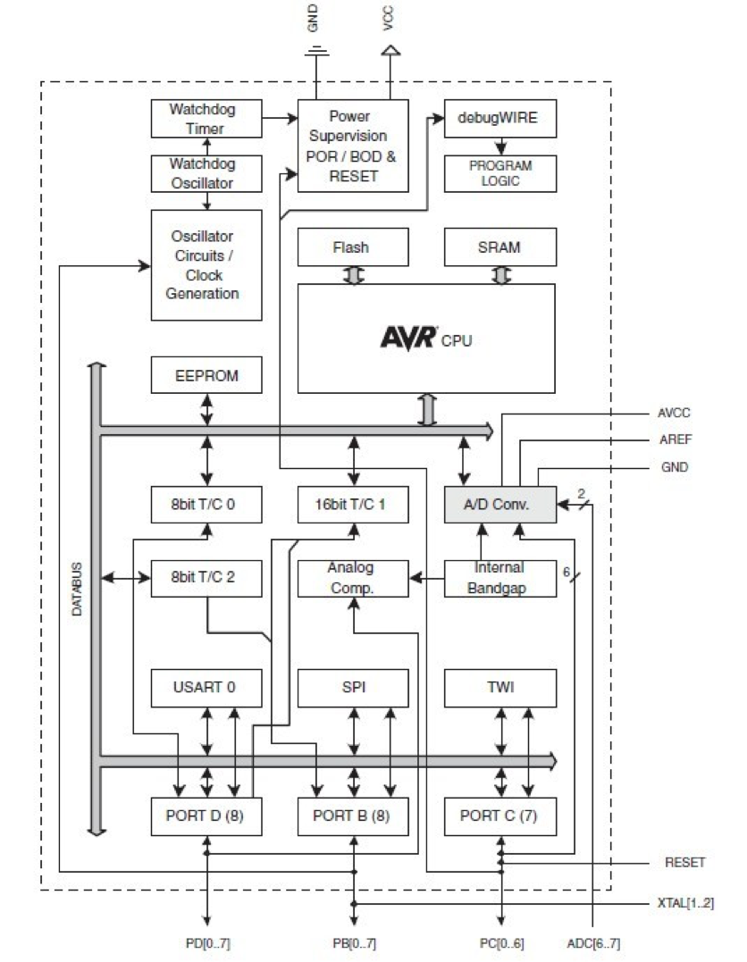
I have decided to work with Atmega328p, you can download the datasheet here.
The main features of ATmega328p are:
- Flash: 32KBytes
- Pin count: 32
- CPU Speed : 20 Mhz
- SRAM : 2Kbytes
- Data EEPROM: 1024bytes
- General Purpose I/O Lines: 23
- SPI: 2
- I2C: 1
- USART: 1
- ADC: 10 bit
- ADC channels: 8
- 8 bit timer/counts: 2
- 16 bit timer/counts: 1
- PWM channels: 6
- Temp. Range (deg C): -40 to 125 ºC
- I/O Supply Class: 1.8 to 5.5
- Operating Voltage (Vcc): 2.7 to 5.5V
- Speed grade:
- 0 to 8 Mhz at 2.7 to 5.5V
- 0 to 16 Mhz at 4.5 to 5.5V
- Low power consumption
- Active mode: 1.5 mA at 3V . 4Mhz
- Power-down mode: 1 uA at 3V
- Watchdog: Yes
- Debug Interface: debugWIRE
The Atmega328p-au architecture is based on the RISC architecture.
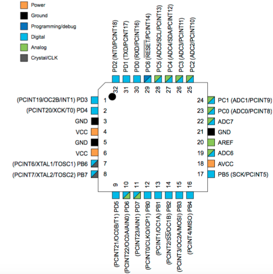
The pinout of this microcontroller is presented in the next Figure. The port B, C and D are programmable with multipurpose.
Read a microcontroller
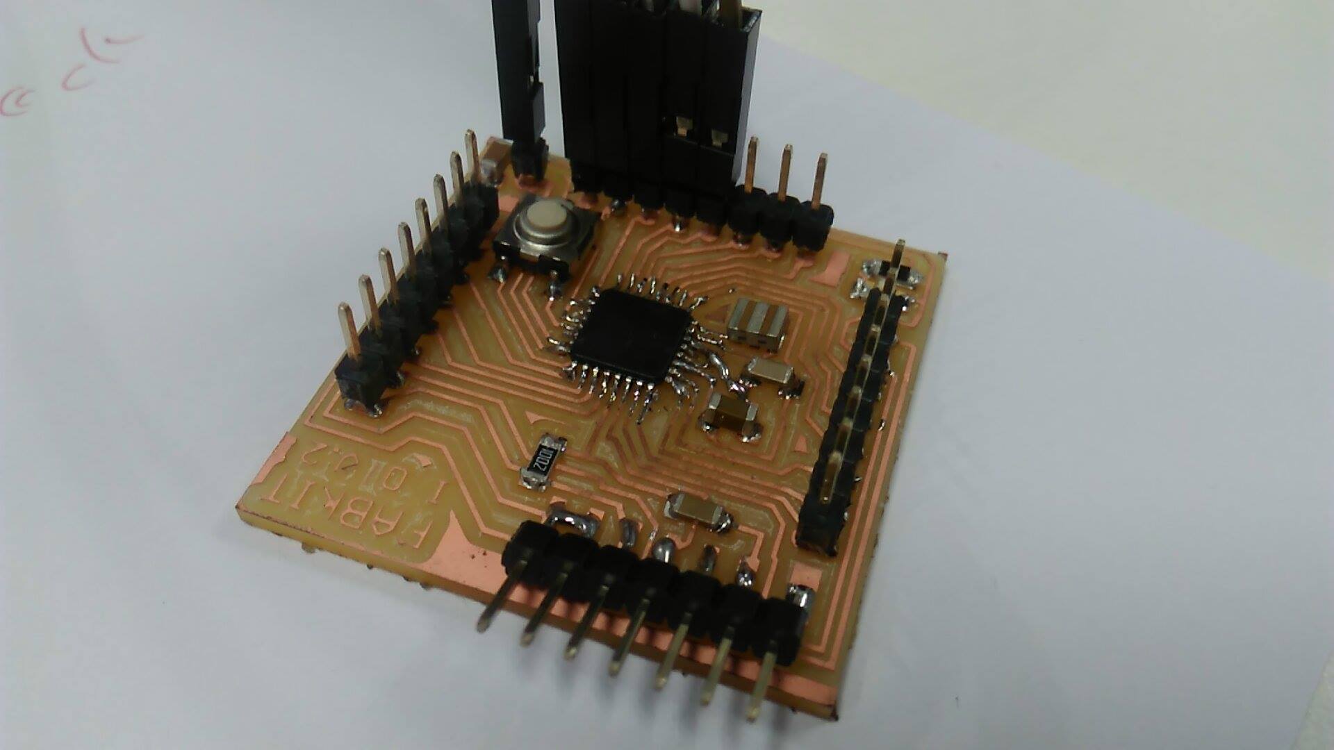
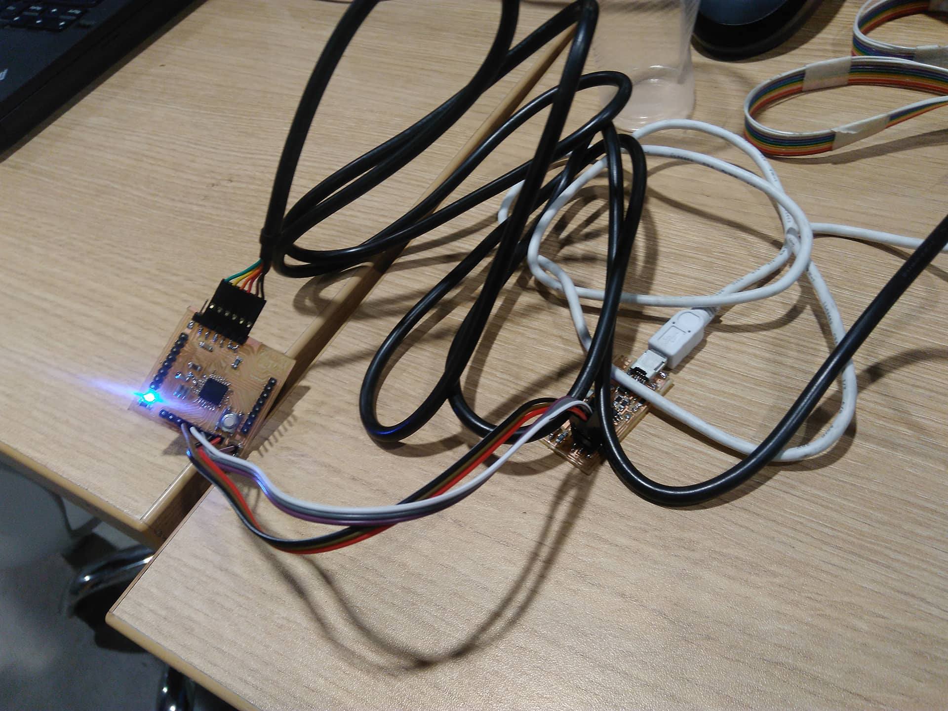
I make a Fabduino v2 , after milling and soldering the board, it shows in right image.
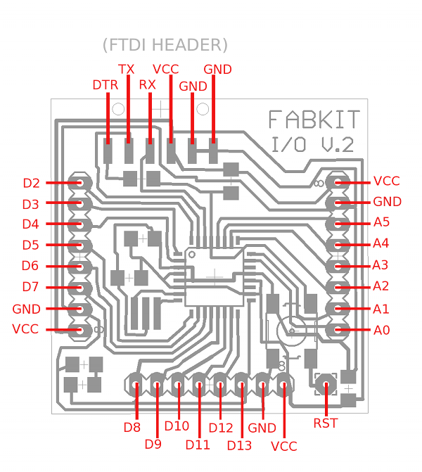
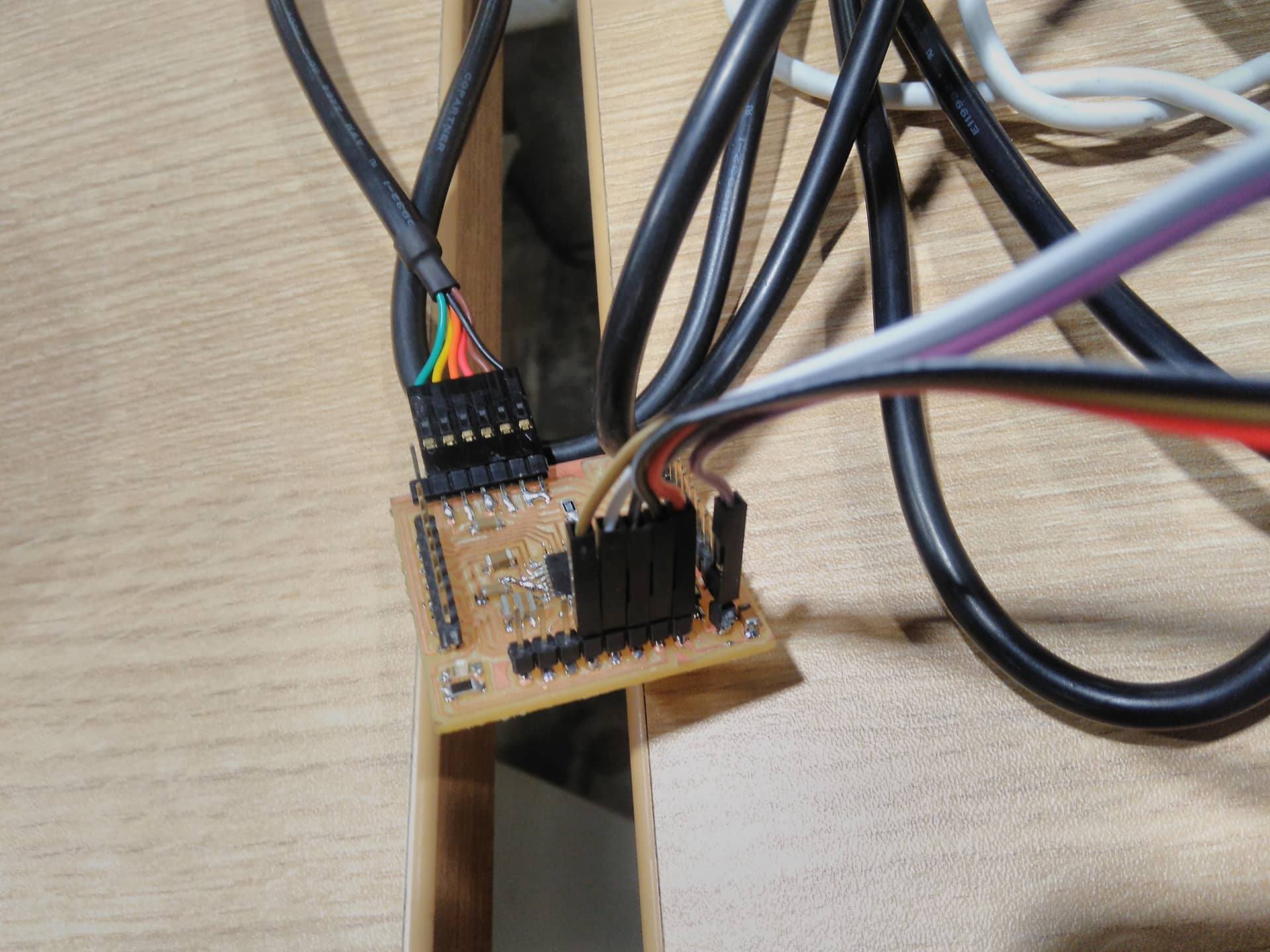
In order to connect the FabISP and FTDI write, in my case I forgot the position of pins MISO/RESET/MOSI/GND/VCC so I have check the diagram of fabduino and fabisp. The pin 13 is SCK, pin 12 MISO, pin 11 MOSI and RESET, VCC and GND are connected in the same pins fabISP/Fabduino. After connecting the wires and FTDI, we have lunched Arduino IDE to program atmel328. So we must edit the environment settings with :
- Board: Arduino Pro and pro-mini
- Processor: ATmega328( 3.3V 8Mhz)
- Programmer: USBTinny
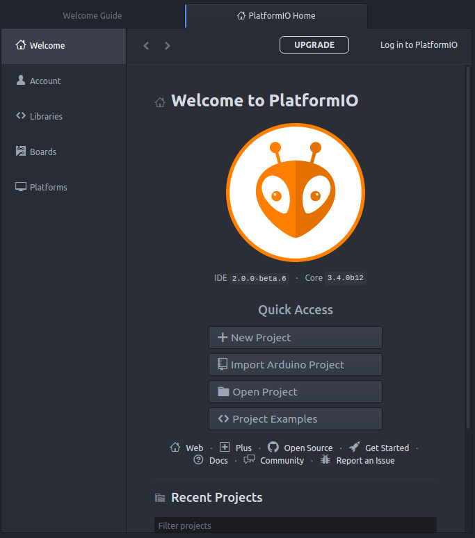
Programming Fabduino in PlatformIO IDE
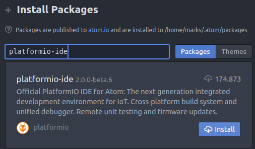
I found a platform to program over Atom which is called PlatformIO IDE. It was installed following the tutorial The steps are followed to install are:
- Open Atom editor
- Click on, Menu: Edit > Preferences > Install
- Search platformio-ide packages, install and restart
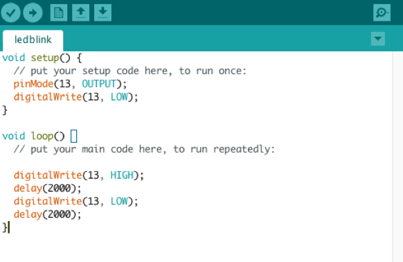
The blink led project with platform is created in the next steps:
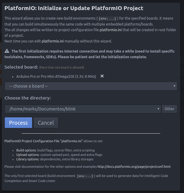
- Open menu PlatformIO >> PlatformIO Home
- In the new GUI, we have selected the board ArduinoPro (3.3V, 8Mhz) and the directory to save the project
- In the directory src of the project, we add cpp file
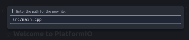
-
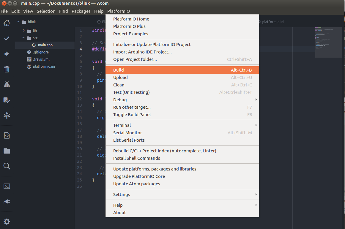
Create blink code in the main.cpp. The project is builded with build menu, and uploading with upload menu. Additionally, we must configure the file platformio.ini which is the configuration file with these parameters:
[env:pro]
platform = atmelavr
board = pro8MHzatmega328
framework = arduino
upload_protocol = usbtiny
The upload_protocol represents the ISP that we use to upload the program. The source code can donwload here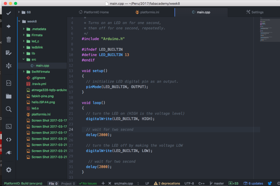
Programming Fabduino in Python
We install the package Python-Arduino-Command API according this tutorial. The first step was install the package with the command pip install arduino-python . We have developed a blink led using port /dev/cu.usbserial-FTGZIDCK . The source code shows in left side. Also, you can download the source, here
from Arduino import Arduino
import time

board = Arduino('9600',port="/dev/cu.usbserial-FTGZIDCK")  #plugged in via USB, serial com at rate 9600
board.pinMode(13, "OUTPUT")
led_pin = 13

while True:
    board.digitalWrite(led_pin, "LOW")
    print "LOW" # confirm LOW (0)
    time.sleep(1)
    board.digitalWrite(led_pin, "HIGH")
    print "HIGH"  # confirm HIGH (1)
    time.sleep(1)