Input devices
The assignment for this week is to measure something: add a sensor to a microcontroller board that you have designed and read it
Planning
- Reviewed the week lecture
- Light sensor: useful for my project
Light sensor
I have decided to replicate the IR light synchronous detection. The principle under a light sensor is based on the reflection of a light beam on the body. The ray that can be measured either the returned luminosity or its flight time. In the lecture this principle was implemented by a phototransistor where it is sensitive to the light ray of the environment and led. This device manages to capture the led light when they reflect on an object another material.
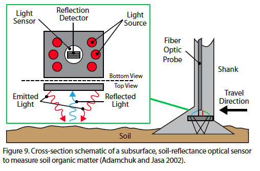
With these considerations Niel created this circuit considering the reflection of a led on a phototransistor mounted on a PCB that process their signals in ATtiny45. So we are going to redraw the circuit on Eagle
Make a board
Our board is a redrawing in Eagle. Before making the circuit we had some questions about:
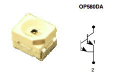
- Which type of phototransistor would we use? FabLab ESAN provides three kinds of this element, they are:
- Darlington NPN
- Phototransistor flat clear 1206
- Phototransistor flat top bk 1206
- Which LED can we use? At the begining I have considered to use an IR led but another time was not equal wih the original version. Even so we will use an IR led in another time.
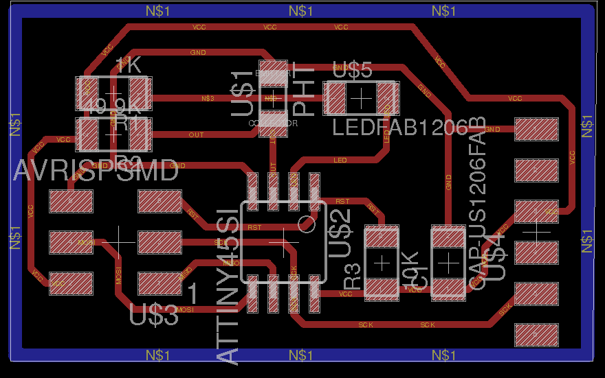
Its schematic created:
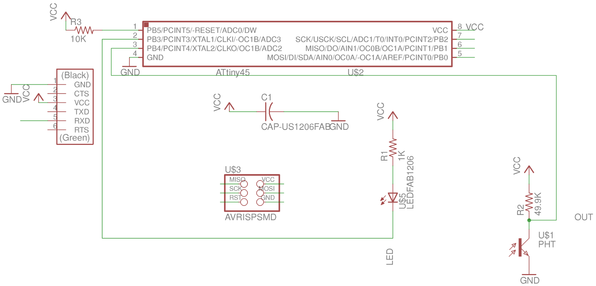
The list BOM:
| Part | Value | Device | Package | Description | |
| C1 | CAP-US1206FAB | CAP-US1206FAB | C1206FAB | ||
| R1 | 1K | RES-US1206FAB | R1206FAB | ||
| R2 | 49.9K | RES-US1206FAB | R1206FAB | ||
| R3 | 10K | RES-US1206FAB | R1206FAB | ||
| U$1 | PHT | PHOTOTRANSISTOR-NPN1206 | OP1206 | ||
| U$2 | ATTINY45SI | ATTINY45SI | SOIC8 | ||
| U$3 | AVRISPSMD | AVRISPSMD | 2X03SMD | ||
| U$4 | FTDI-SMD-HEADER | FTDI-SMD-HEADER | 1X06SMD | ||
| U$5 | LEDFAB1206 | LEDFAB1206 | LED1206FAB | LED |
Board Production
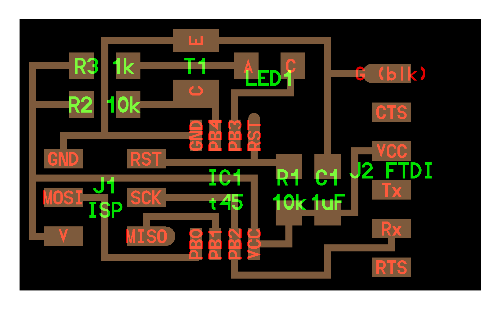
We have exported the board to png file. So we got the following images. Traces:
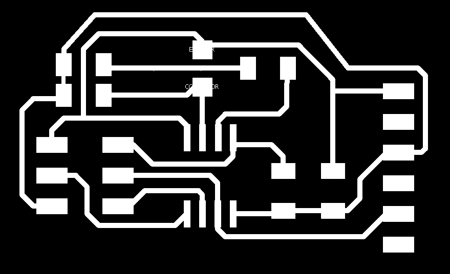
Outline:

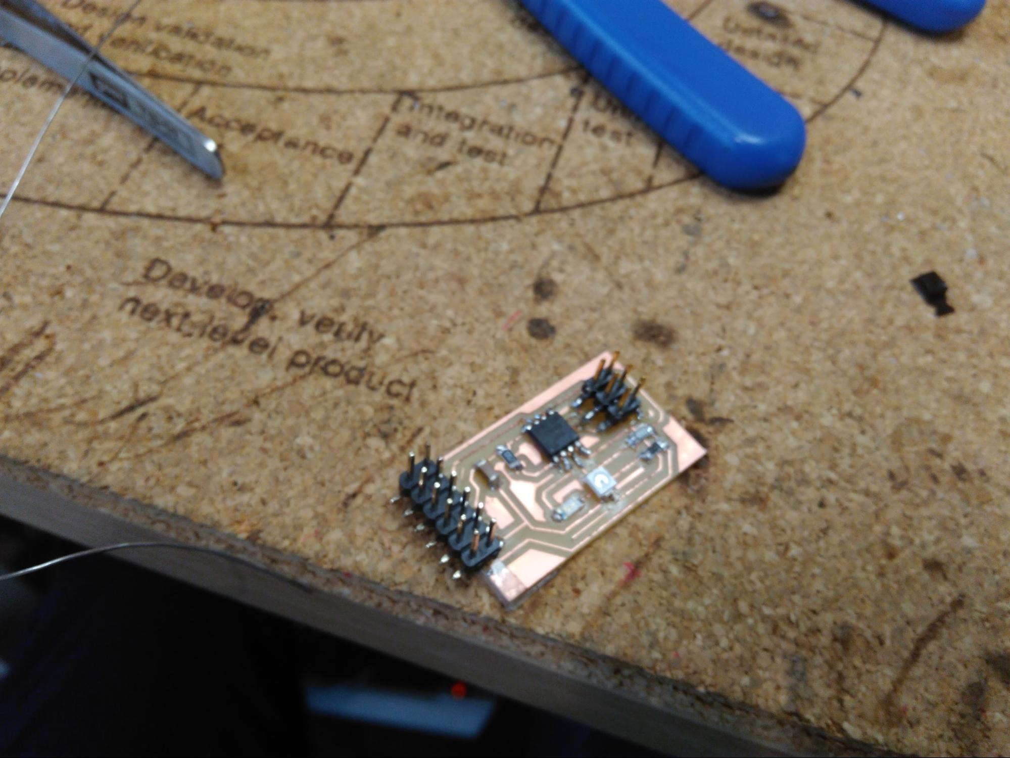
Final board:
Programming
We simply use the code given in class. After downloading the code here in a folder we compiled with the command: sudo make -f hello.reflect.45.make program-avrisp2. The original code shows in the right part of this paragraph. When we finish compiling without errors, but sometimes I had errors in compiling. These could fix with the correct soldering. After compiling without errors we executed python code with the command: python hello.reflect.45.py /dev/ttyUSB0 As a parameter to the source file .py is the port to which the FTDI is connected. And finally we got
Original code
// hello.reflect.45.c
// light reflection synchronous detection hello-world
//    9600 baud FTDI interface
// Neil Gershenfeld
// 10/25/12
// (c) Massachusetts Institute of Technology 2012
// This work may be reproduced, modified, distributed,
// performed, and displayed for any purpose. Copyright is
// retained and must be preserved. The work is provided
// as is; no warranty is provided, and users accept all
// liability.

#include <avr/io.h>
#include <util/delay.h>
#define output(directions,pin) (directions |= pin) // set port direction for output
#define set(port,pin) (port |= pin) // set port pin
#define clear(port,pin) (port &= (~pin)) // clear port pin
#define pin_test(pins,pin) (pins & pin) // test for port pin
#define bit_test(byte,bit) (byte & (1 << bit)) // test for bit set
#define bit_delay_time 102 // bit delay for 9600 with overhead
#define bit_delay() _delay_us(bit_delay_time) // RS232 bit delay
#define half_bit_delay() _delay_us(bit_delay_time/2) // RS232 half bit delay
#define char_delay() _delay_ms(10) // char delay
#define serial_port PORTB
#define serial_direction DDRB
#define serial_pin_out (1 << PB2)
#define led_port PORTB
#define led_direction DDRB
#define led_pin (1 << PB3)
#define nloop 100 // number of loops to accumulate

void put_char(volatile unsigned char *port, unsigned char pin, char txchar) {
   //
   // send character in txchar on port pin
   //    assumes line driver (inverts bits)
   // start bit
   clear(*port,pin);
   bit_delay();
   // unrolled loop to write data bits
   if bit_test(txchar,0)
      set(*port,pin);
   else
      clear(*port,pin);
   bit_delay();
   if bit_test(txchar,1)
      set(*port,pin);
   else
      clear(*port,pin);
   bit_delay();
   if bit_test(txchar,2)
      set(*port,pin);
   else
      clear(*port,pin);
   bit_delay();
   if bit_test(txchar,3)
      set(*port,pin);
   else
      clear(*port,pin);
   bit_delay();
   if bit_test(txchar,4)
      set(*port,pin);
   else
      clear(*port,pin);
   bit_delay();
   if bit_test(txchar,5)
      set(*port,pin);
   else
      clear(*port,pin);
   bit_delay();
   if bit_test(txchar,6)
      set(*port,pin);
   else
      clear(*port,pin);
   bit_delay();
   if bit_test(txchar,7)
      set(*port,pin);
   else
      clear(*port,pin);
   bit_delay();
   // stop bit
   set(*port,pin);
   bit_delay();
   // char delay
   bit_delay();
   }

int main(void) {
   // main
   static unsigned char count;
   static uint16_t on,off;
   // set clock divider to /1
   CLKPR = (1 << CLKPCE);
   CLKPR = (0 << CLKPS3) | (0 << CLKPS2) | (0 << CLKPS1) | (0 << CLKPS0);
   // initialize output pins
   set(serial_port, serial_pin_out);
   output(serial_direction, serial_pin_out);
   set(led_port, led_pin);
   output(led_direction, led_pin);
   // init A/D
   ADMUX = (0 << REFS2) | (0 << REFS1) | (0 << REFS0) // Vcc ref
      | (0 << ADLAR) // right adjust
      | (0 << MUX3) | (0 << MUX2) | (1 << MUX1) | (0 << MUX0); // ADC2
   ADCSRA = (1 << ADEN) // enable
      | (1 << ADPS2) | (1 << ADPS1) | (1 << ADPS0); // prescaler /128
   // main loop
   while (1) {
      // accumulate
      on = 0;
      off = 0;
      for (count = 0; count < nloop; ++count) {
         // LED off
         set(led_port, led_pin);
         // initiate conversion
         ADCSRA |= (1 << ADSC);
         // wait for completion
         while (ADCSRA & (1 << ADSC))
            ;
         // save result
         off += ADC;
         // LED on
         clear(led_port, led_pin);
         // initiate conversion
         ADCSRA |= (1 << ADSC);
         // wait for completion
         while (ADCSRA & (1 << ADSC))
            ;
         // save result
         on += ADC;
         }
      // send framing
      put_char(&serial_port, serial_pin_out, 1);
      char_delay();
      put_char(&serial_port, serial_pin_out, 2);
      char_delay();
      put_char(&serial_port, serial_pin_out, 3);
      char_delay();
      put_char(&serial_port, serial_pin_out, 4);
      char_delay();
      // send result
      put_char(&serial_port, serial_pin_out, (on & 255));
      char_delay();
      put_char(&serial_port, serial_pin_out, ((on >> 8) & 255));
      char_delay();
      put_char(&serial_port, serial_pin_out, (off & 255));
      char_delay();
      put_char(&serial_port, serial_pin_out, ((off >> 8) & 255));
      char_delay();
      }
   }