Electronic Production
This homework was make an in-circuit programmer by milling the PCB. My homework was divided in three approaches: two failures and one success experiment.
First Approach
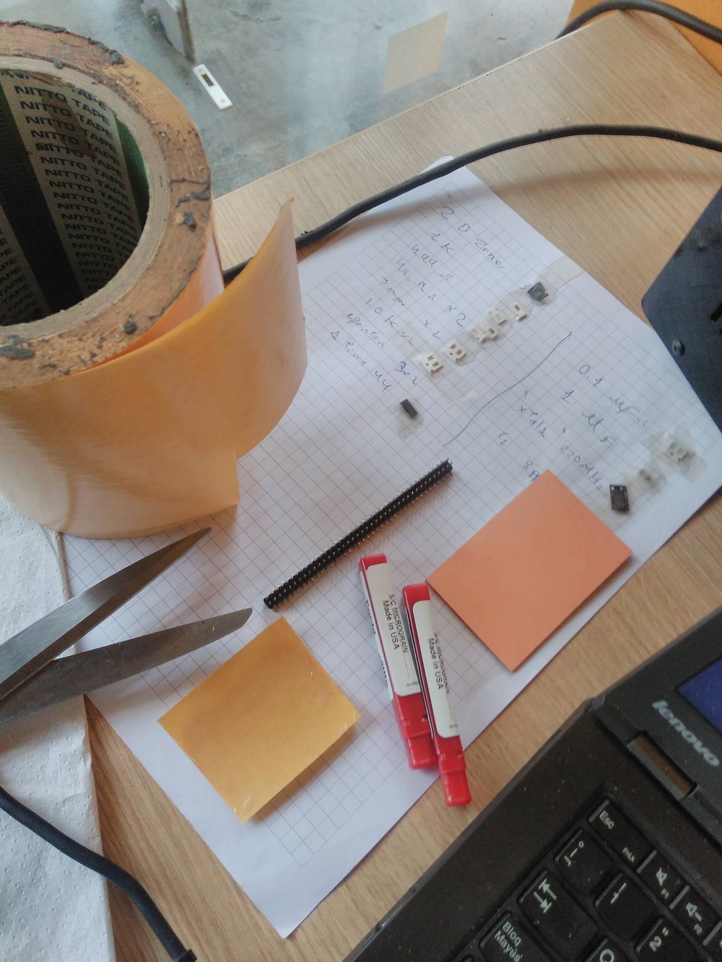
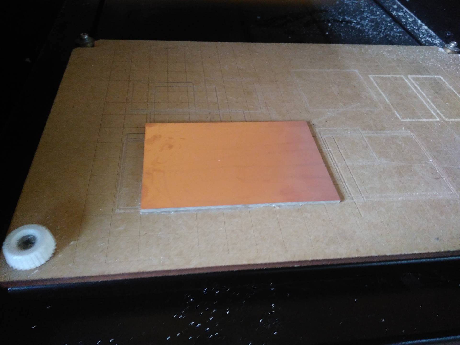
In this initial stage I decided to implement the Andy's FABISP. So we procedded to do. Firstly, we got the materials on the lab, with the stick is push on PCB and we assured to leave bag of air between PCB and stick. Retired the other label of stick to push on the platform on Roland Machina MDX-20. To do the last step, we set up the machine on view mode.
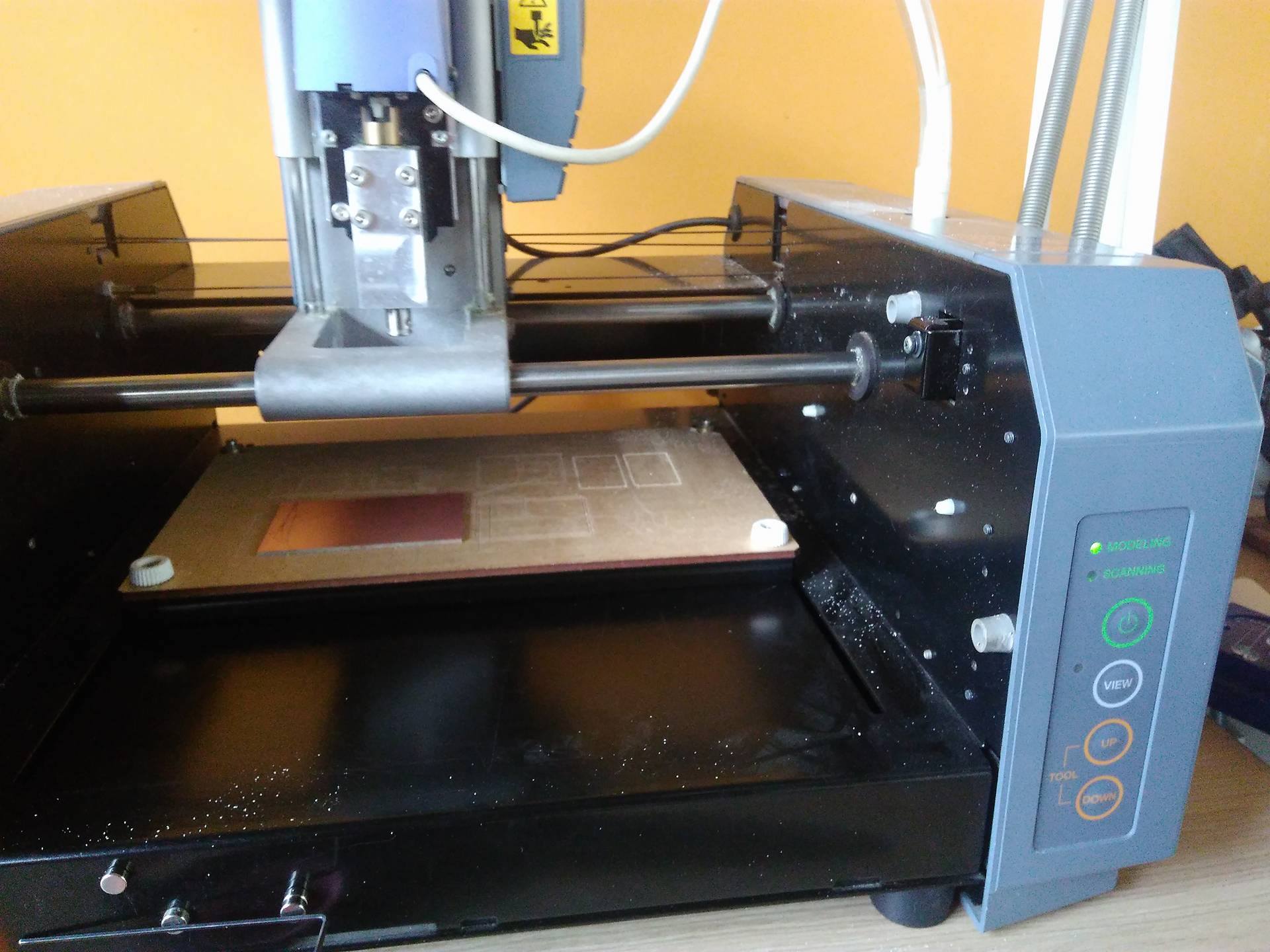
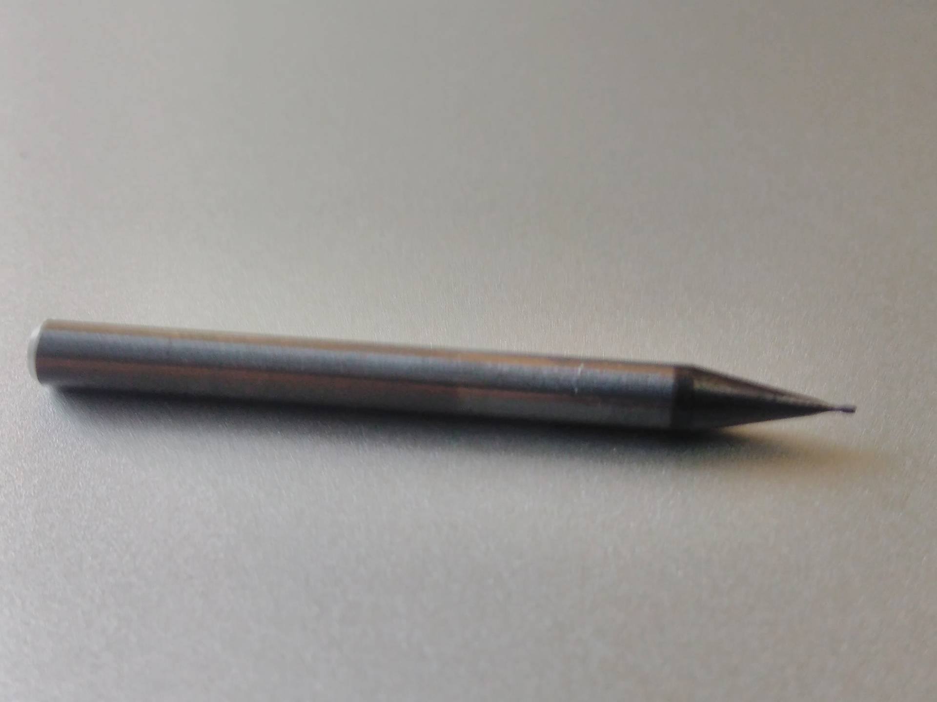
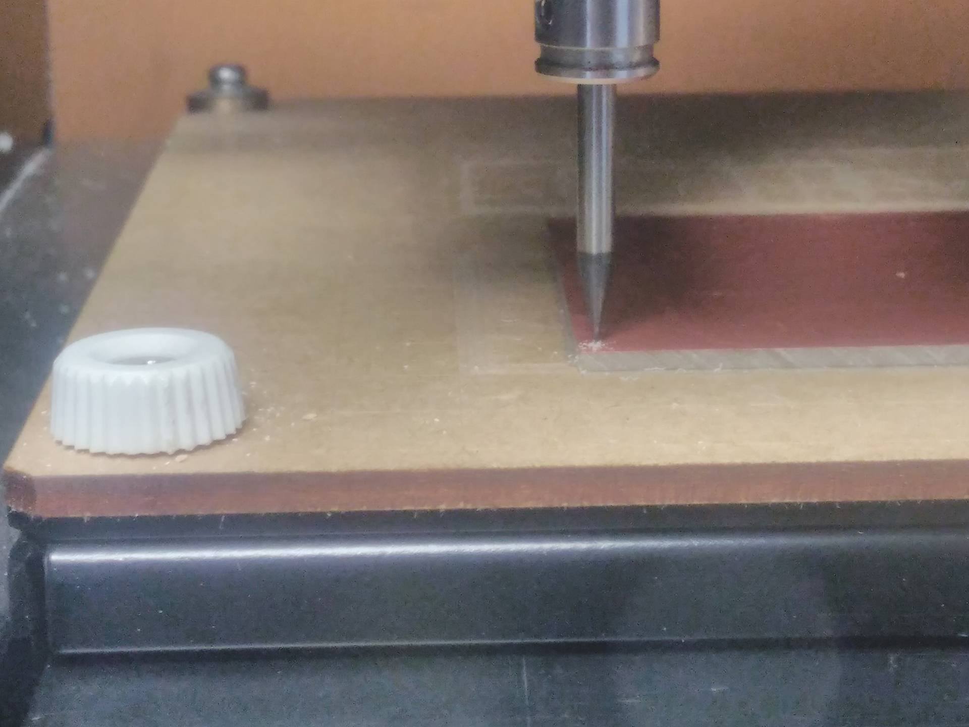
With the correct drill 1/64 to milling PCB , we adjusted it inside the head of Roland. Our platform indicate that our PCB are in the point (20,20) aproximately. I had a little nervous because the drill is extremlly thin.
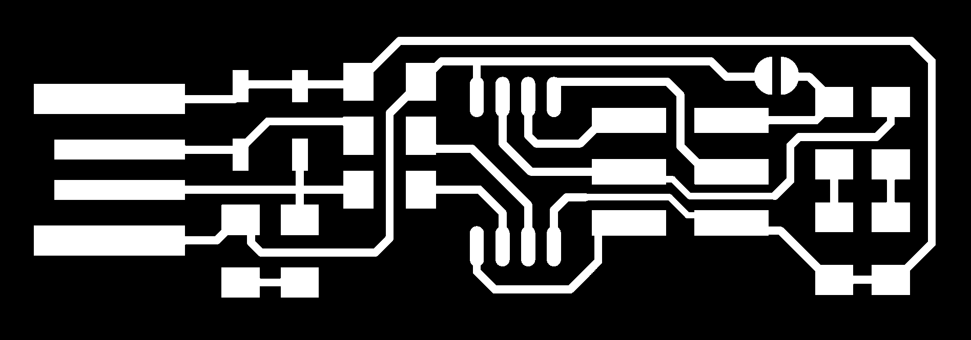
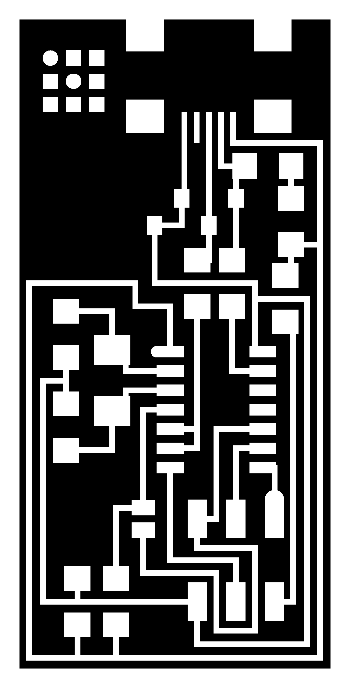
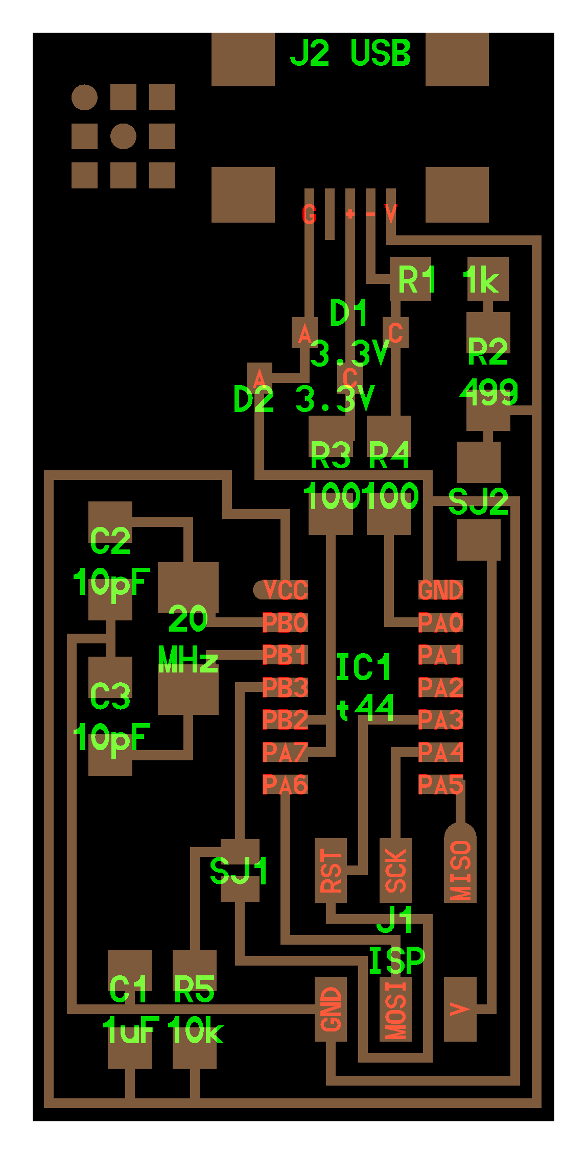
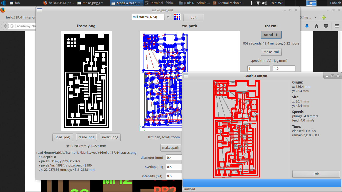
The PNG files for the traces and the board are following accordly the author.
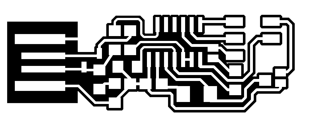

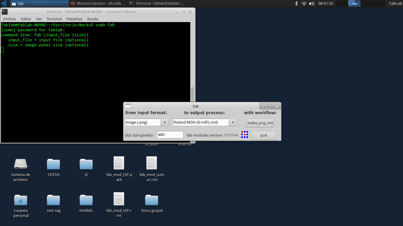
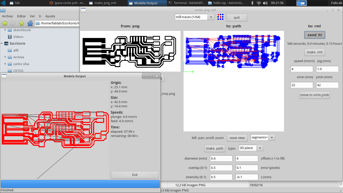
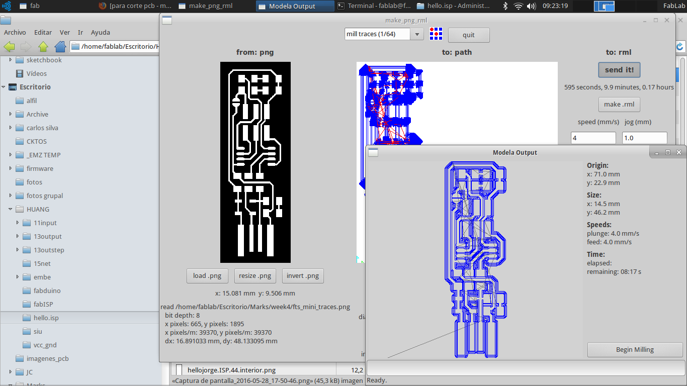
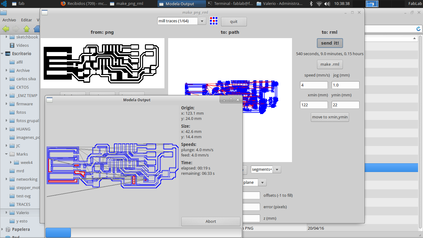
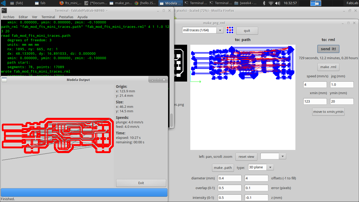
Now, we sent the image to milling PCB. To do this task we lunch a terminal on Linux and we write the command sudo fab. A gui is show. Accordly, this task we select image(.png) as input format and Roland MDX20 mil as output process. Pushed a make png_rml. In the program we load the traces images, in the list box in top we select mil traces(1/64). For this experiment we considered the error(pixel) with 0.1, the kind of view is segments+traces+path. In this case we move the drill head to the position (22,22).
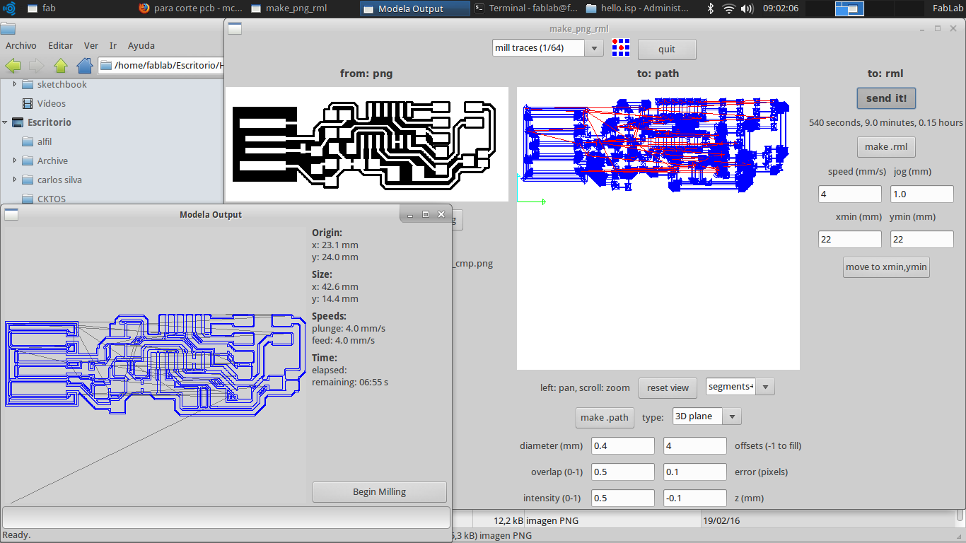
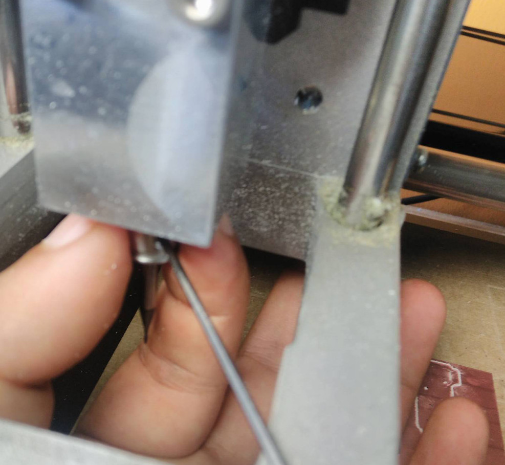
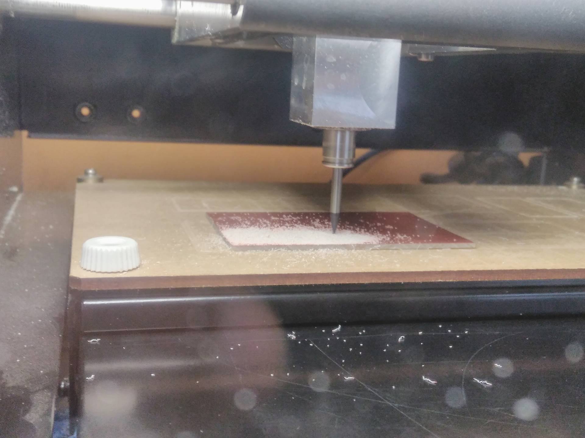
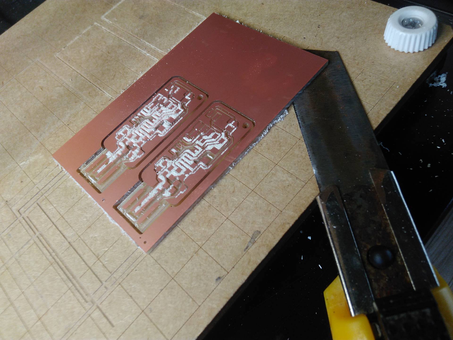
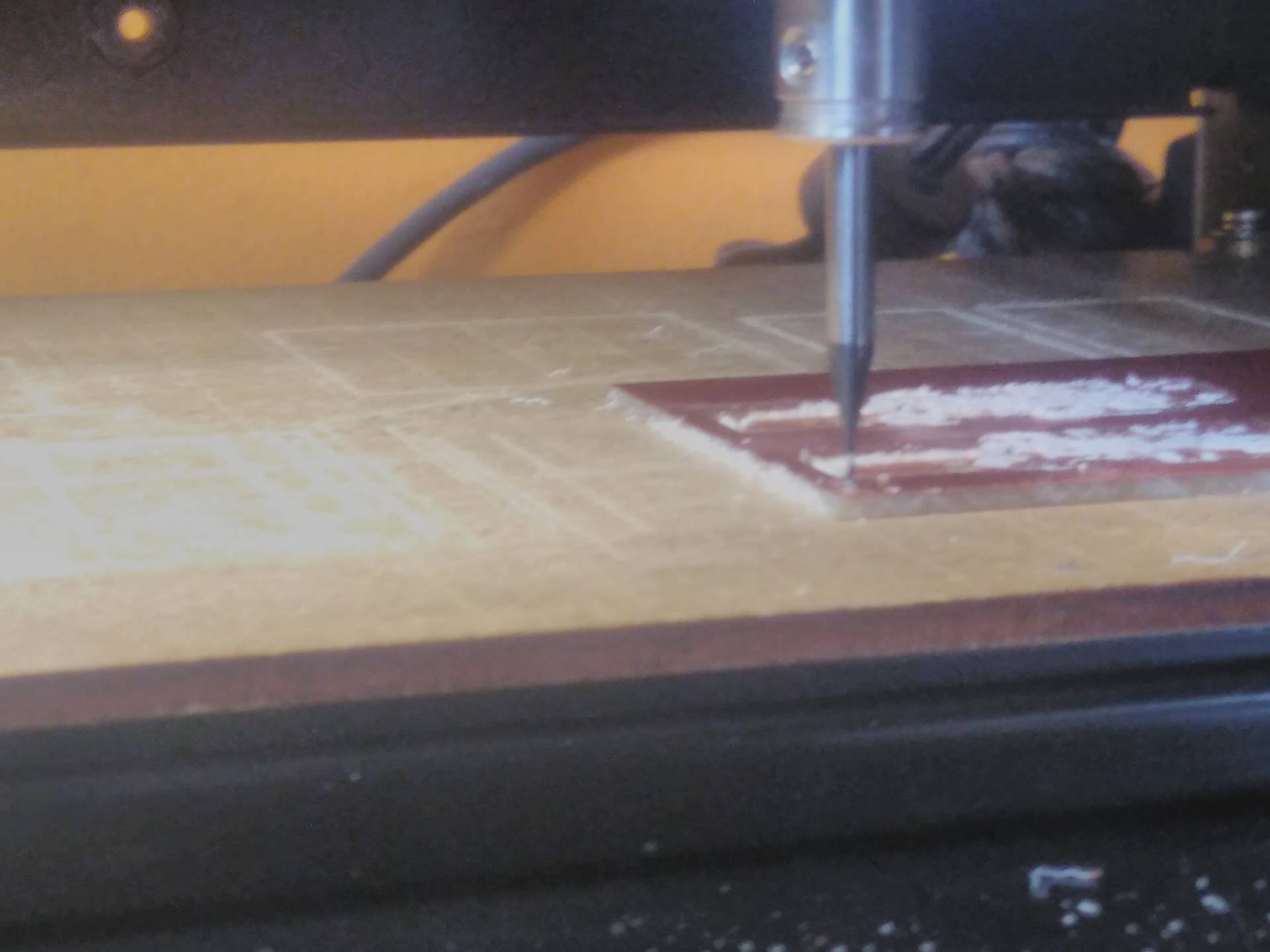
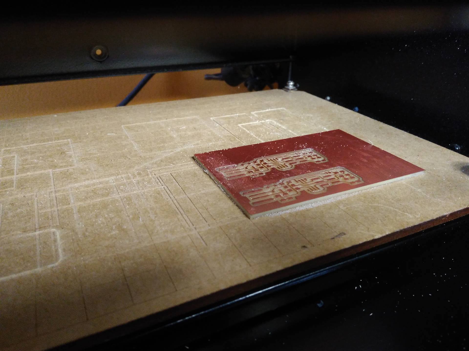
The drill should be milling the PCB surface. It was so complicated at the begining because while we push the button down of the machine, we should care to not destroy the drill. But we did it! , clicked the button make .rml and following sent it!. Finally, we pressed begin milling and the milling task was done by 7 minutes for this PCB. We did mill two extra circuits in the board, we only change the origin of the drill head to (22, 42), it was differente because this point was translated twenty points in Y axis, this size is the width circuit. Another circuit was rotated to keep on the PCB.

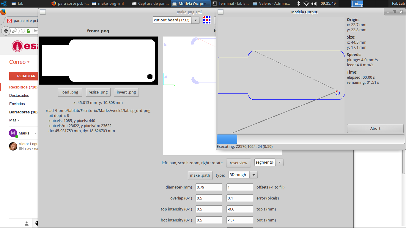
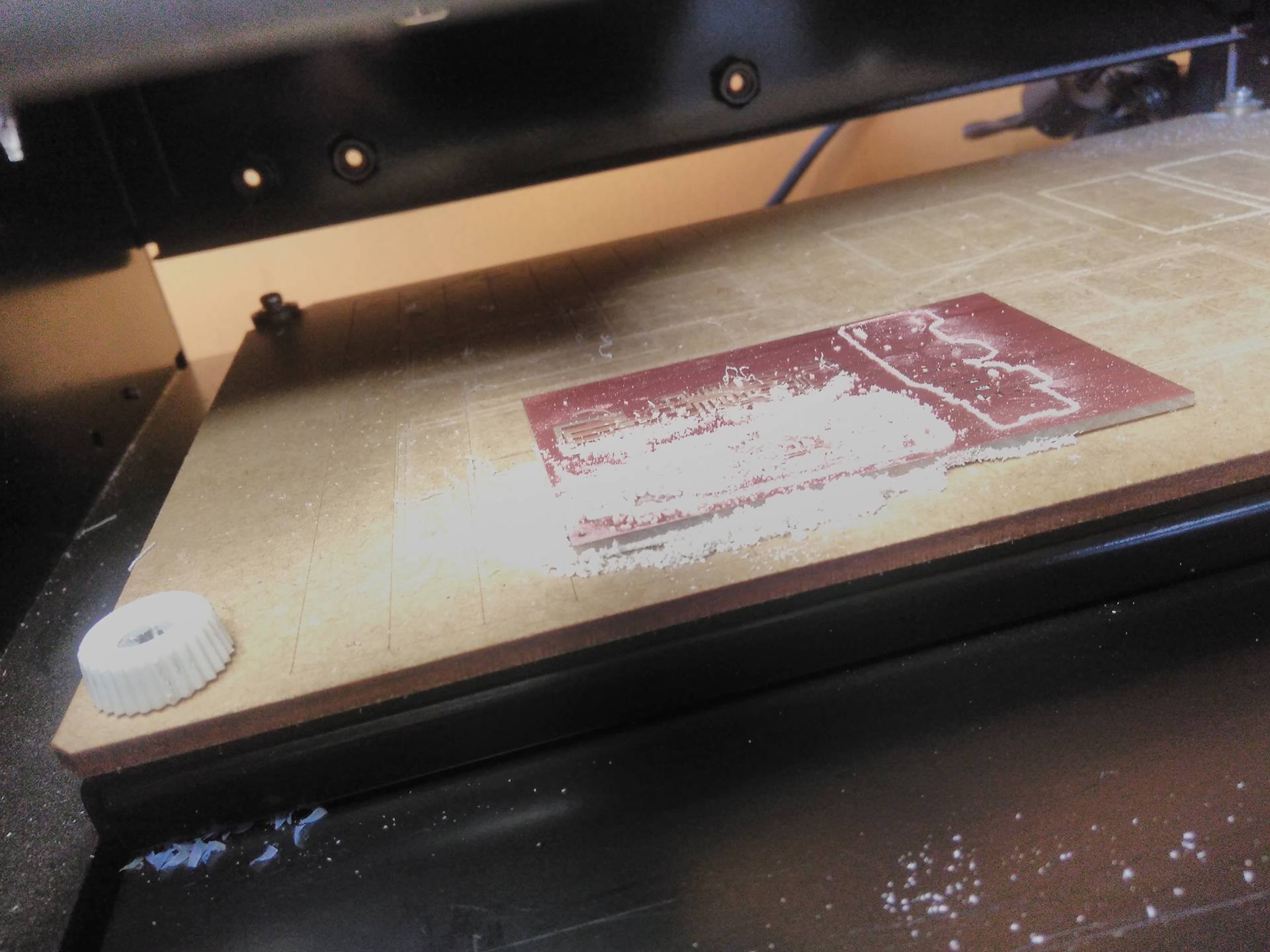
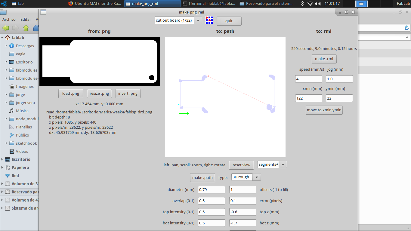
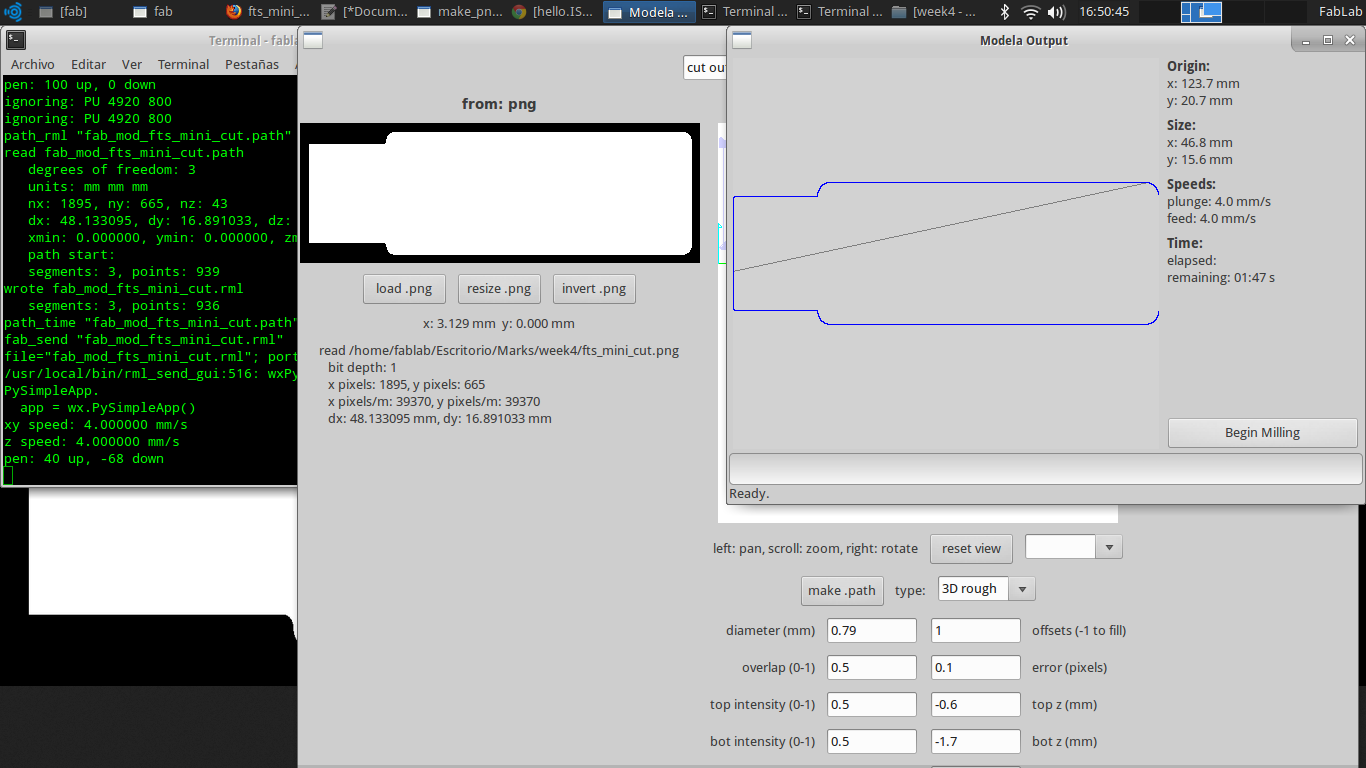
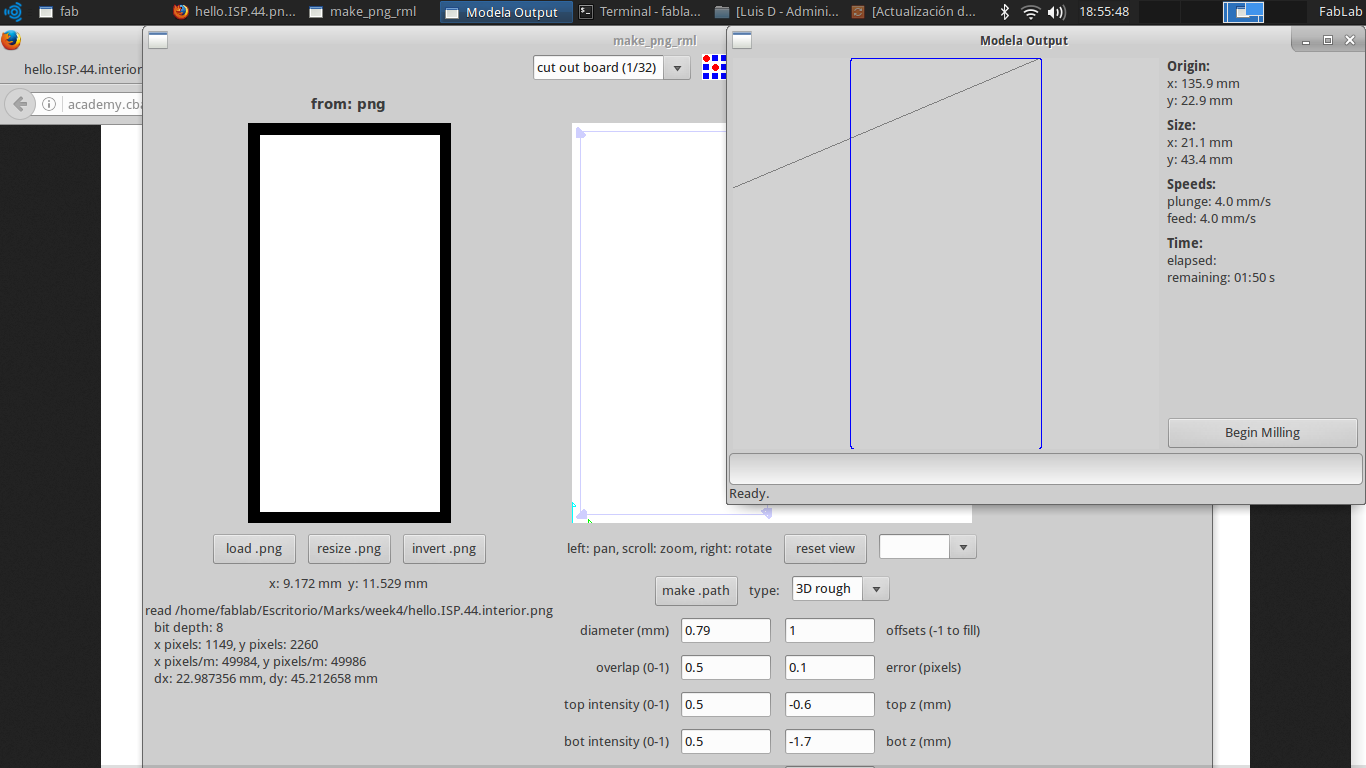
After three milling circuits we loaded the interior image. The machine is turn off to change the drill 1/32. In the program we changed the task by cut out board (1/32). The process to cut out PCB is the same of milling with calibration of drill on the board. We are three PCB so we started the cut out in the initial point of each circuit. Unfortunately, the PCB has moved when the drill was milling. We power off the machine but the drill was broke and the circuits were incomplete.
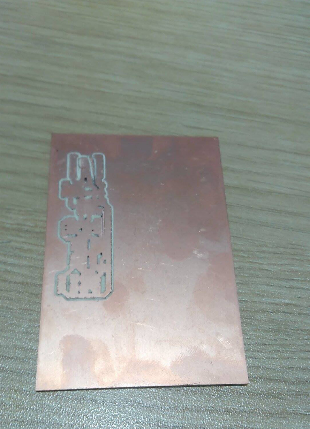
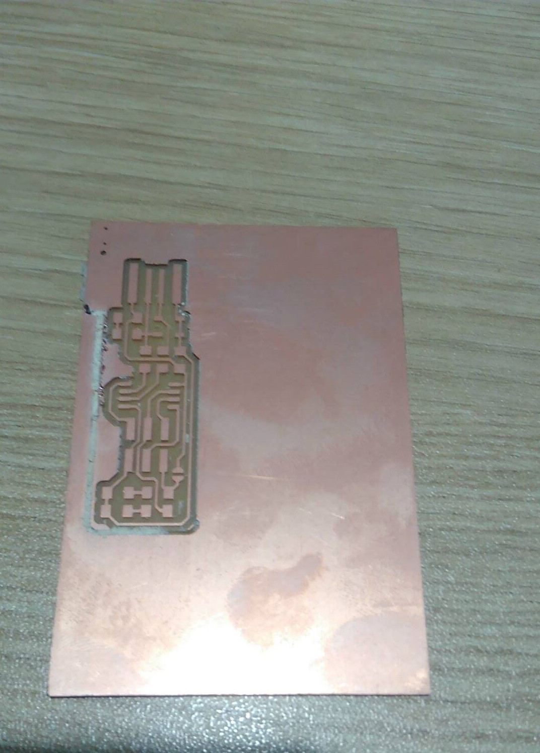
I tried one time more, we have repeated the same process of milling.
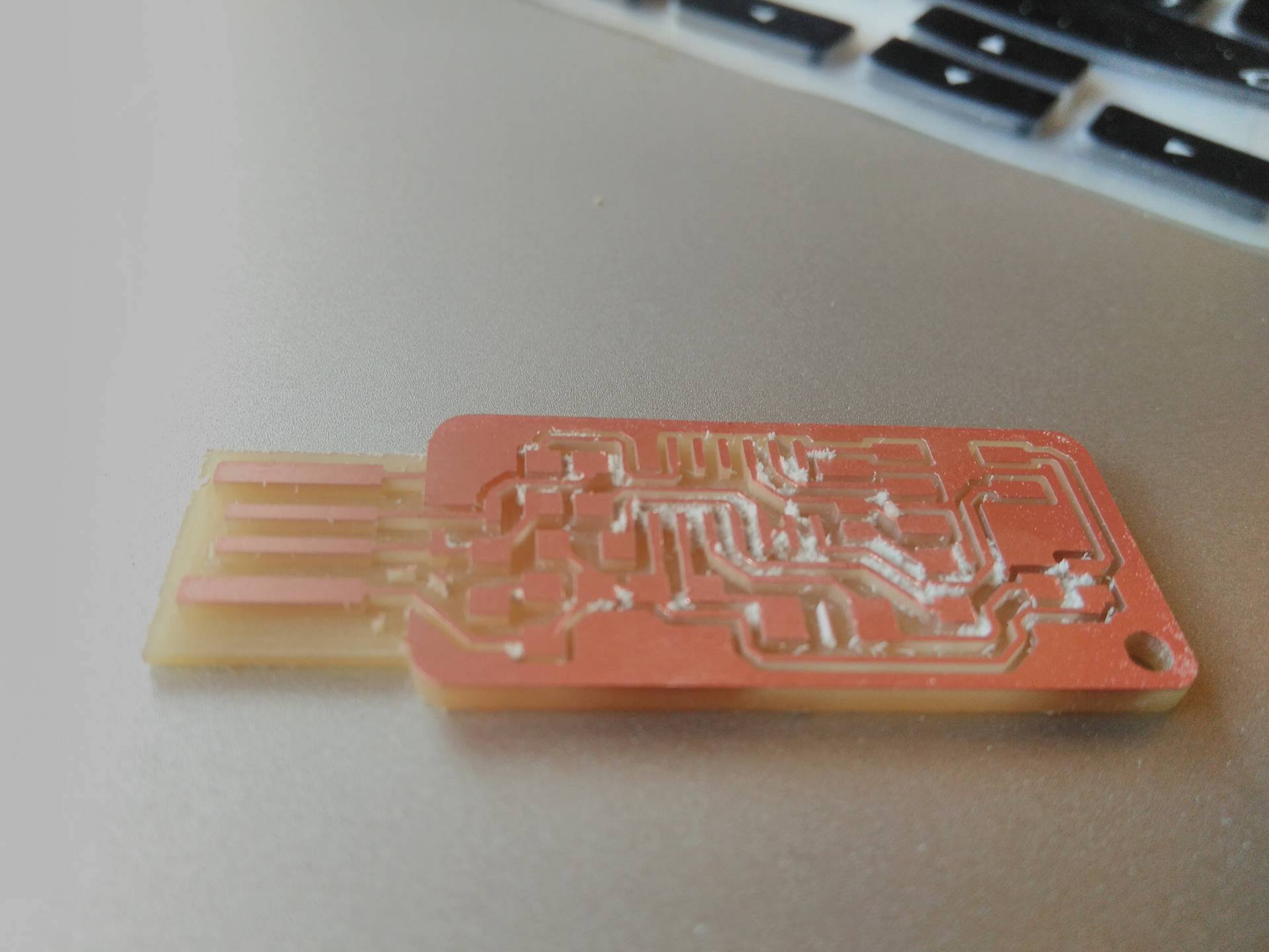
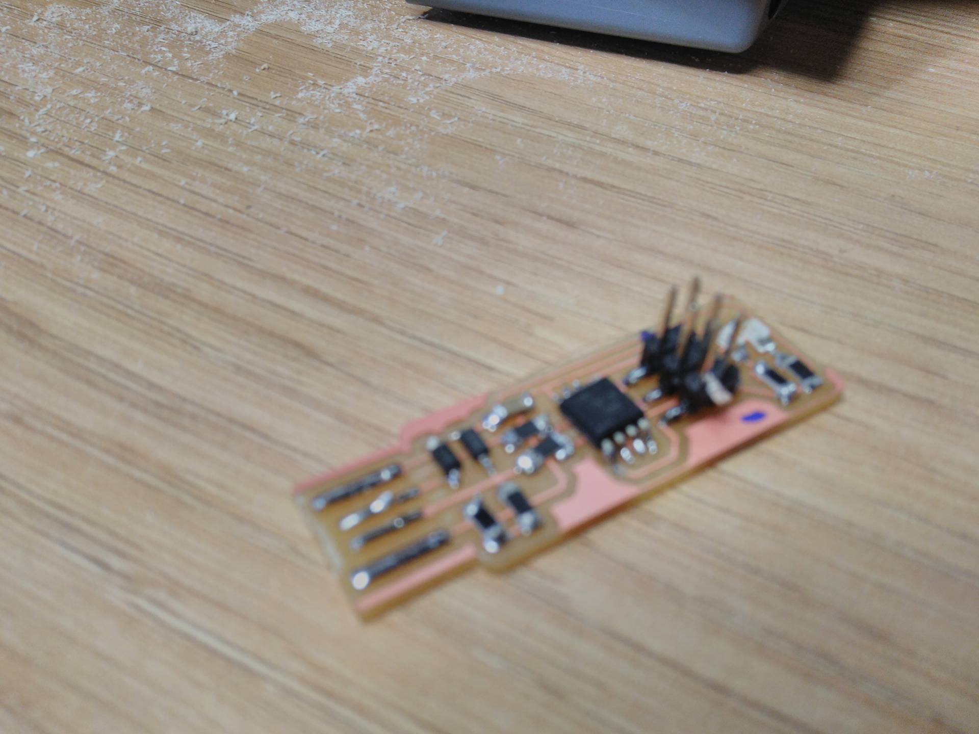
We completed the circuits :D!!!. After we have soldered the elements in the board. The soldering took hours because it was hard to sold elements with tinny dimensions.
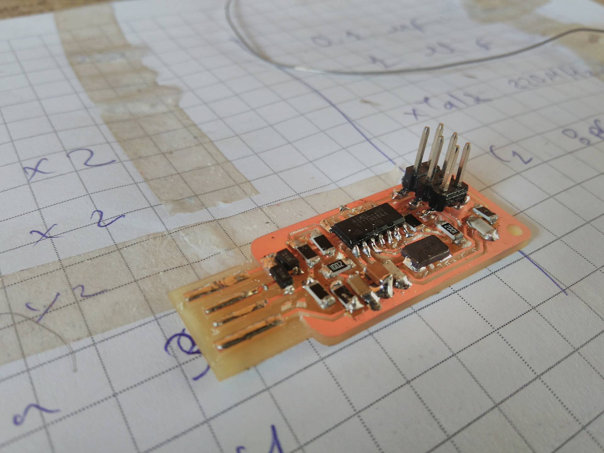
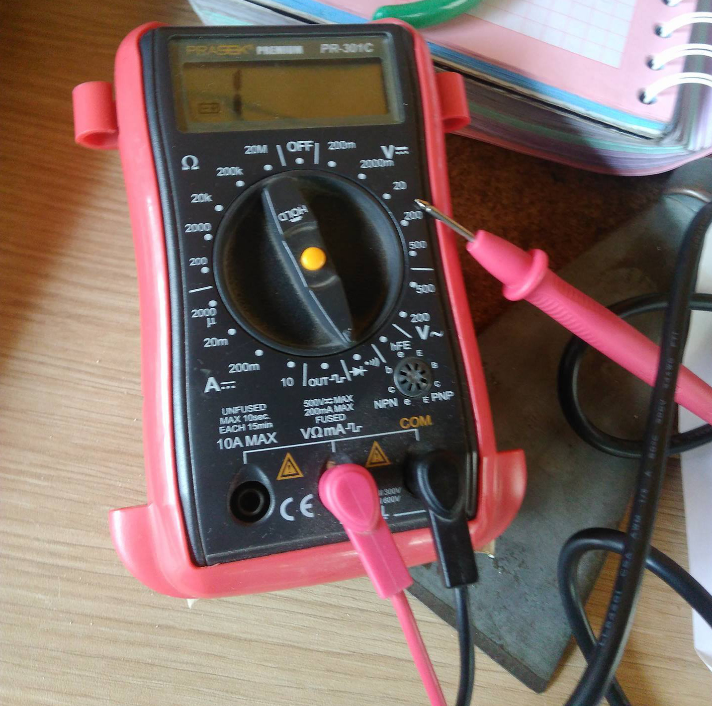
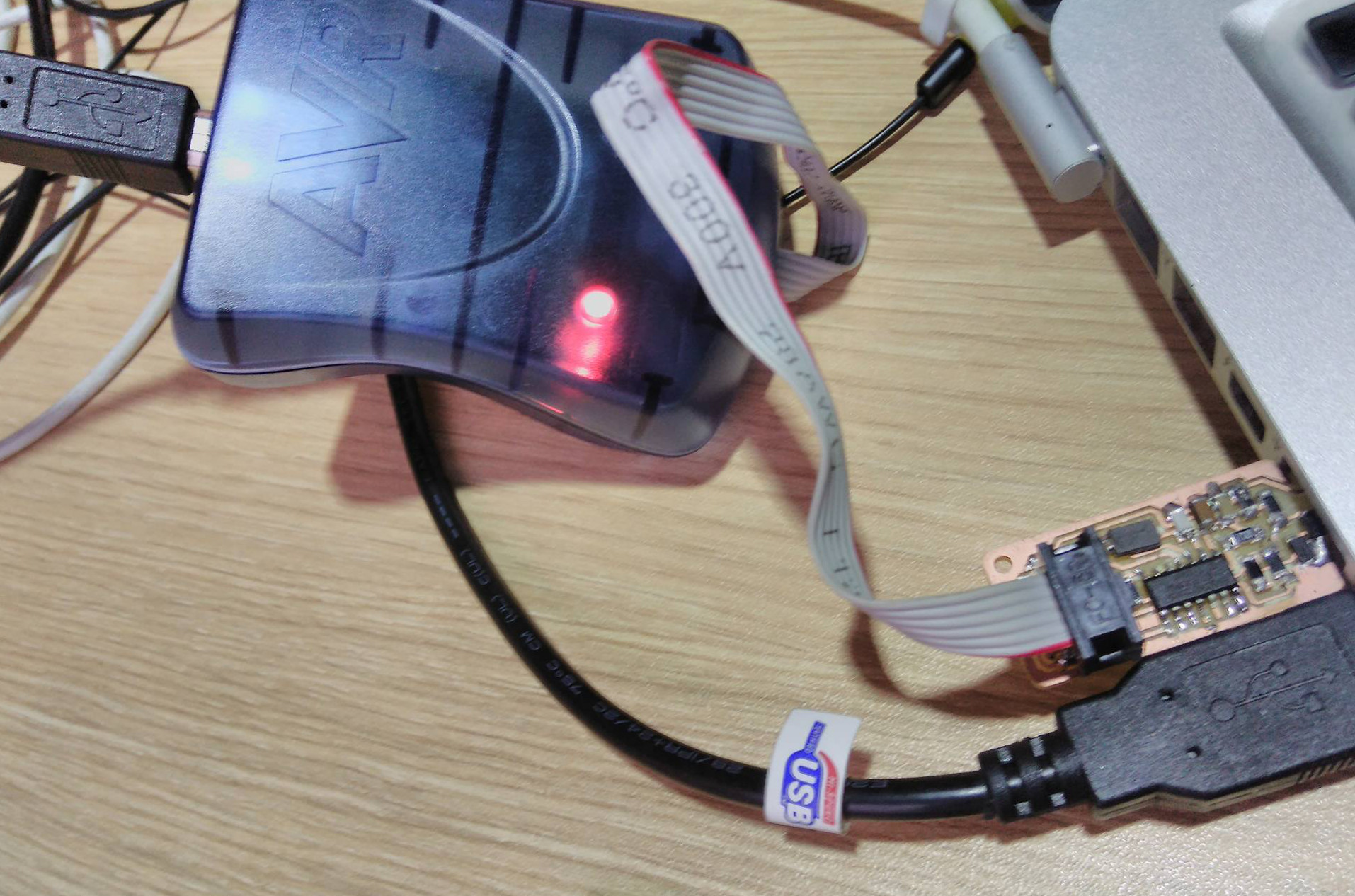
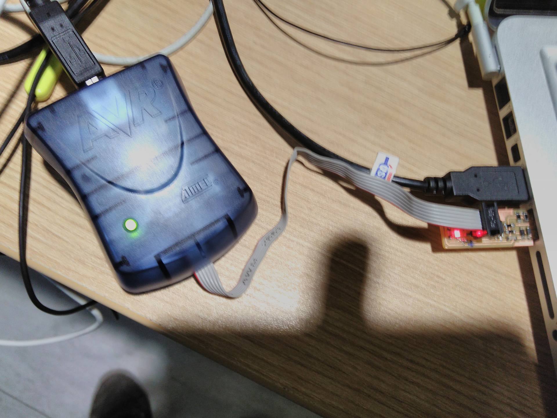
To test if our PCB is correct we use AVR ISP which has a circuit to check the correct implementation. It lights green if the circuit is ok and other colours to failures in the PCB. We got a red light so we took a multimeter to analyze the continuity of the circuit, I spend several hours veryfing the position and soldering of elements in my PCB. But I found always ok. So I declined to continue with model.
Second approach
This opportunity we decided to make a Brian's ISP. This circuit has less element than the last PCB. So we have done the same milling process that we described in the last section.
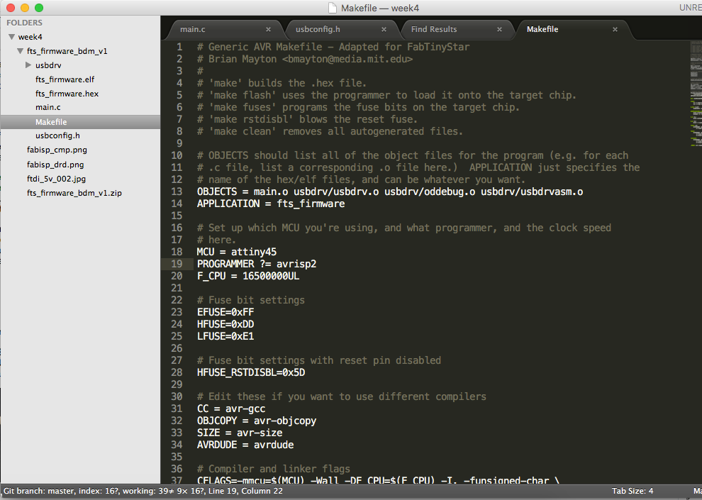
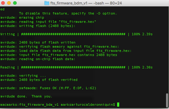
After extracting the firmware in a folder, we modified the Makefile changing the PROGRAMMER value of ustiny by avrisp2. In the terminal we directed to the firmware folder and compile the code with the command make, it has generated a .hex file and sent to the microntroller with avrdude -c avrispmkii -p attiny45 -U flash:w:fts_firmware.hex:i in the terminal. I was said "oh yes, I did it!".
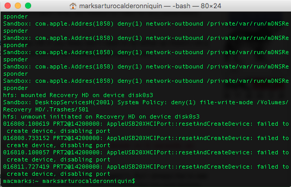
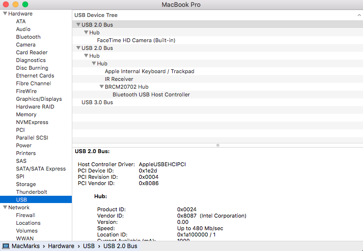
Unfortunately, my ISP was fault because the laptop did not detect. To verify these situation was with the command sudo dmesg , I check the elements and other situations that the author commented in his site . After hours with the problem was never changed. The system report of About this mac reported the same.
Third approach
I have continued trying the last ISP by two times more, I broke a drill and one PCB has moved in milling process. The chance was clear in this situations. So I decide to change one more time.
Finally, I decided to do the simple FabISP.

We did the milling and cutting process.

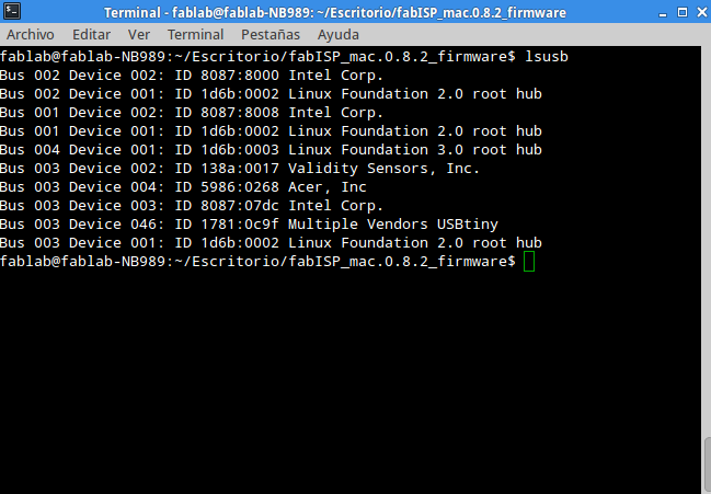
When we tested our circuit with AVR, it got a green light. So it was ok. Now, we downloaded the firmware and extract in folder. We execute the next command in the terminal which was in the firmware folder:
- make clean
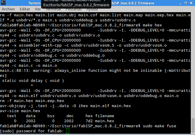
- make hex
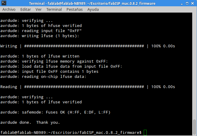
- sudo make fuse
- sudo make program
My finall conclusion are:
- The innovation starts with simple things. In this task ocurred the inverse process.
- We learned more persistance that technical skills.
- Frustation and failures are part of growing.