Computer-controlled cutting
This homework was composed by two assigments:
Tasks
- Group
- Individual
- Project related
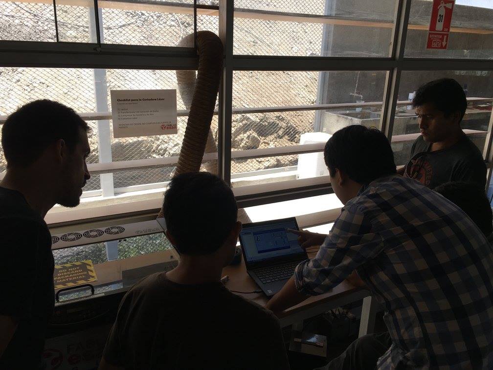
Group assigment
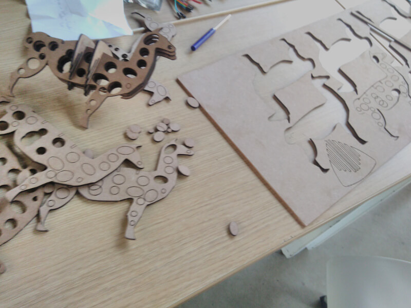
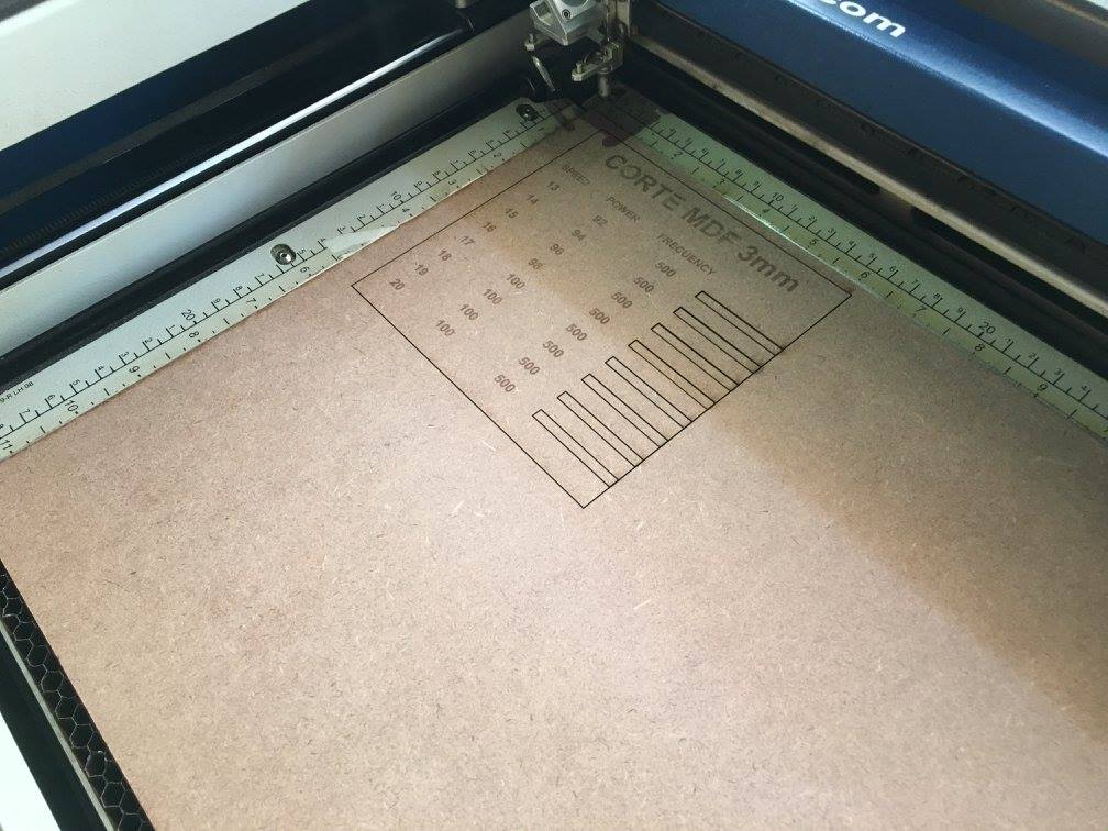
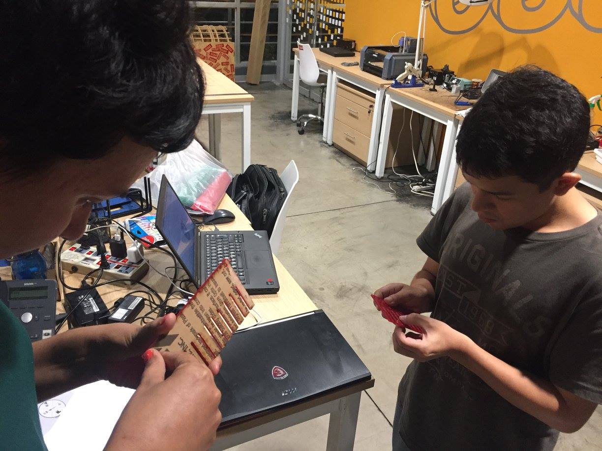
My team have been testing the Epilog laser mini with the help of workers of FabLab ESAN. They have explained all details about the machine and considerations as how to clean the headboard and glass of this machine. After that we sent simple things in cut and raster configurations. But my team was considered to create a collection of samples with configurations in different materials such acrylic, mdf, leather and pino wood base. The process was cut one the shape of collection, and for each sample we sent to cut with differents settings. Several designs in cut laser caused that dirty on the head of machine, although we turn on air compressor. So we learn to clean the head after using the machine by several minutes. After this task I decided working in a design of keychain, so I did it! .
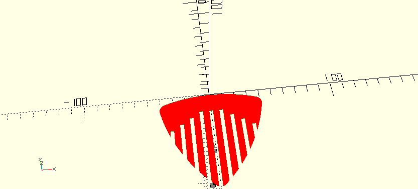
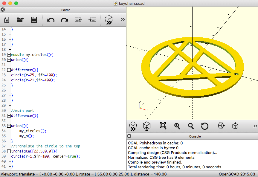
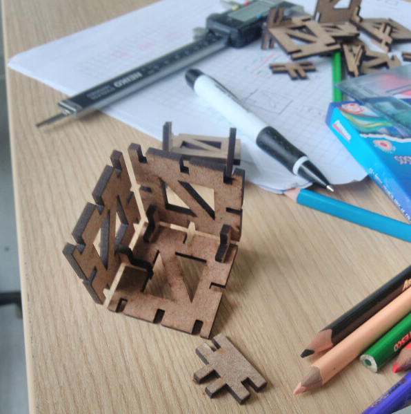
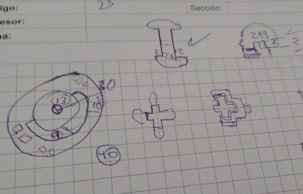
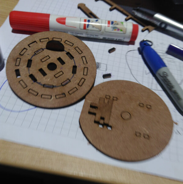
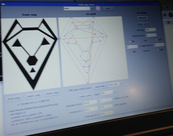
Epilog laser machine offers two modes: laser cut and engraving or combined . The first one need configuration as autofocus option which calibrates the laser head. Piece of Size represents the dimension of the board where we put material to cut, this machine accepts a piece of 600x300mm2. Finally, we must setup laser parameters such as speed of head, power of light and wave frequency. The keychain settings shows in the image central belong here.
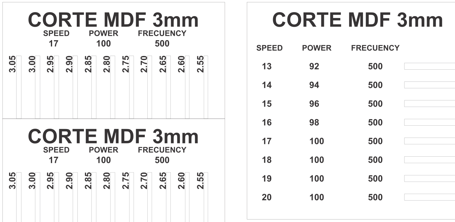
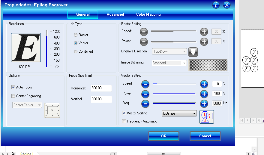
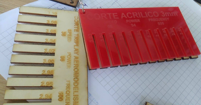
- Speed: 10
- Power: 98
- Frequency: 5000

Conclussions
This machine allows to cut or engrave some materials like MDF, fommi, vynil, paper, and other kind of wood base. But it can not work with metal. The parameters to use change according the material, we read more details in its manual . My team could see variation in pressfit according the power, speed and frequency; with a inappropriatte values of these can separate more the unions.Individual assigment
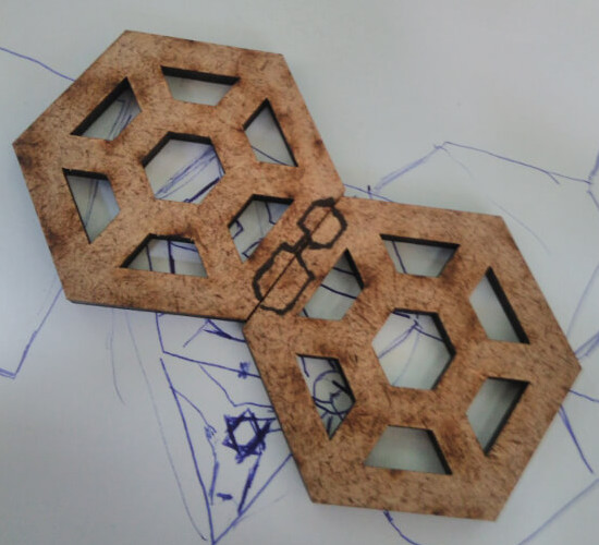
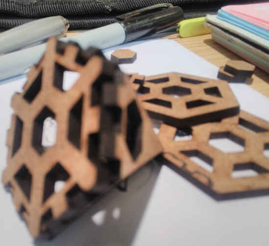
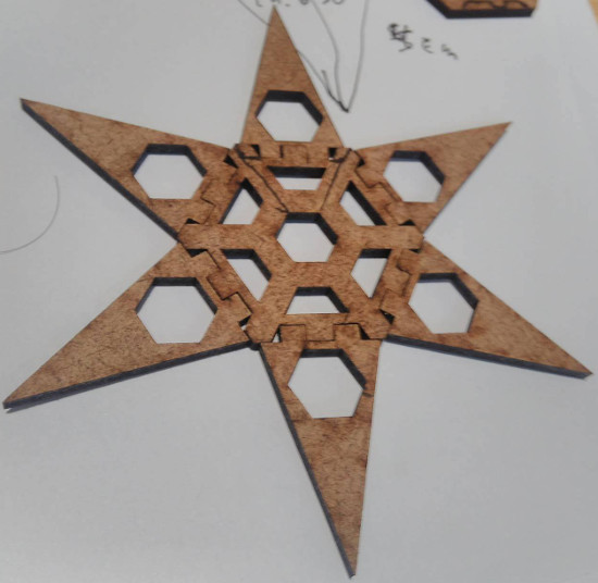
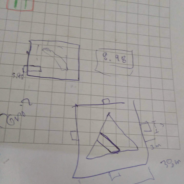
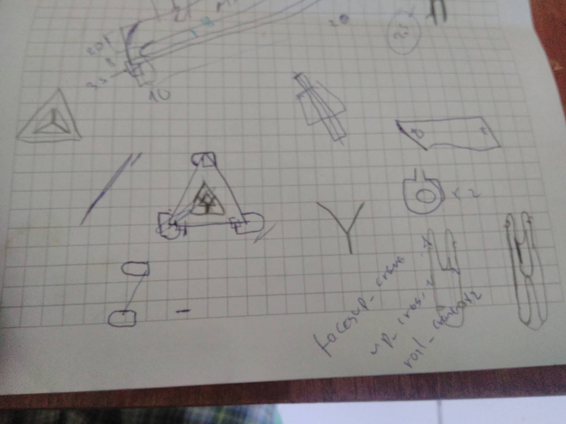
This homework are divided in three parts: press-fit construction, vynil cutting and project cut. In the next paragraph we can see the construction of our press-fit kit. The construction of press-fit was a crazy journey of ideas and testing for me,like a jewish in the way to the promise land, because I knowed that I will finish it, but I did know nothing about parametric design neither modular designs. At the beginning we decided to create a turtle shell, so we tried to create it with hexagonal pyramids. This was not a good idea adding my frustation using Inventor, but I reconsidered my bad situations as part of successful homework, I took the though "it's only the first iterations!". The follow images show my first sprint. The side hexagonal measure was around 20 mm and the high of triangle 40 mm, the problem with this design was the unions to close the pyramid. My union are perfect if I want to create a star as it show in the image, but it was not a good deal to build a pyramid.
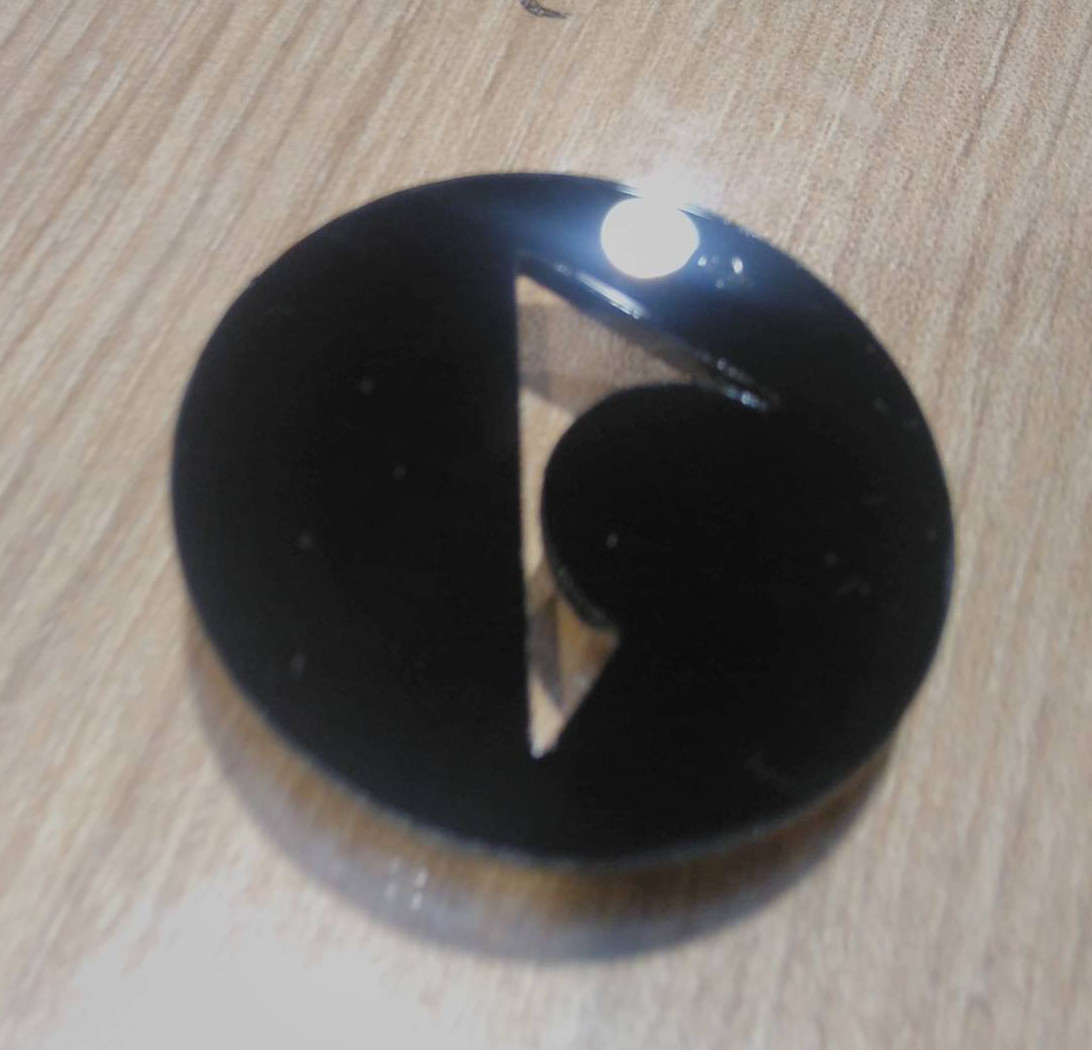
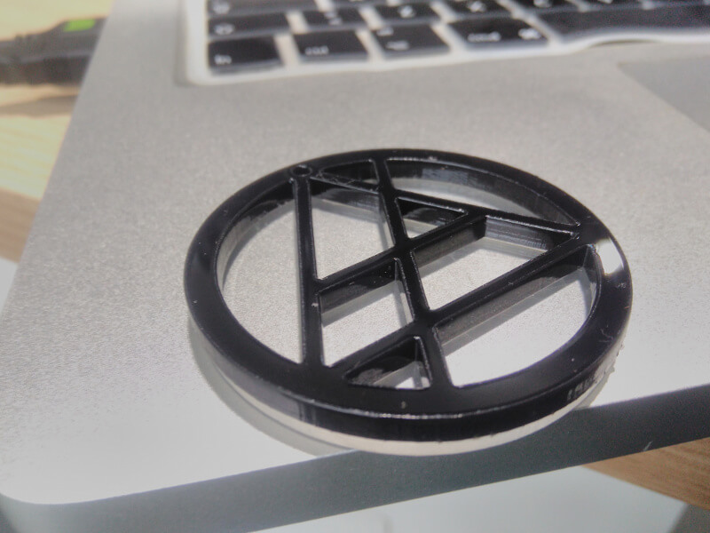
We aborted the shell design so we decided to create other parametric logo with Inventor. I took around several hours to create a simple logo. I have just remembered the lecture about OpenSCAD and how you can program your designs. Then, I took a quickly tutorial in Youtube. After concluiding the tutorial I design the same logo in code which took around fifteen minutes. The image belong here was cutting with my design in OpenSCAD. The right image shows the CAD design with code. This design was so simple, it is only two concentric circles separate by 6mm, a triangle inside the interior circle, and adding two lines. You can download the source file here for more details .
The next opportunity
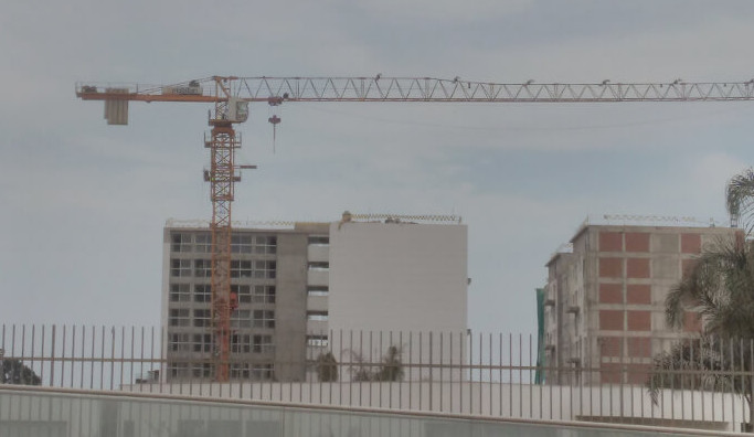
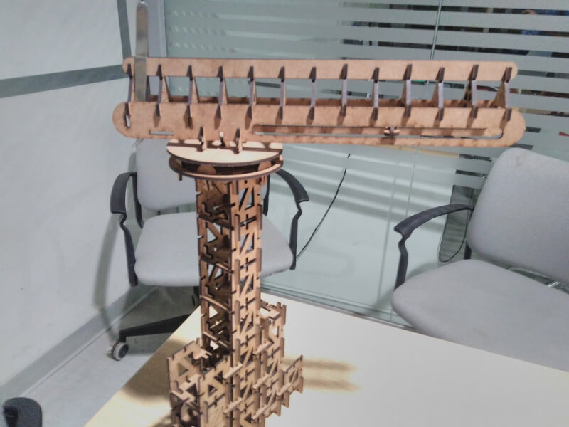
At the moment I was experience using cut laser machine and desigining few things, but I still have a clear idea about my modular design. One day I went to my work normally, but I have never seen around the way, when ocassionally I decided to look around the round and I saw a tower crane in building construction, Eureka!. This was a perfect idea to create a modular press-fit because each floor of the tower crane is the same in dimensions and shape with exceptions in cabin and its arm, but the arm can have a modular design.
Tower design
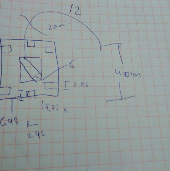
The challenge that I was faced how to design a part of tower. I tried one time without success, so I chanced my original design by other with some specifications as side length of 40mm, six holes to unit with other structures of the time. In the right image we show my final draft for the face of the tower. Additional considerations as 2.96mm of space for unions with MDF of 3mm, the answer to the question: why do we choose 2.96mm and not other widths?. The answer is that we tried with others but without success to adjust with pression and not result impossible to disassemble, the perfect width was 2.96mm. The source file is here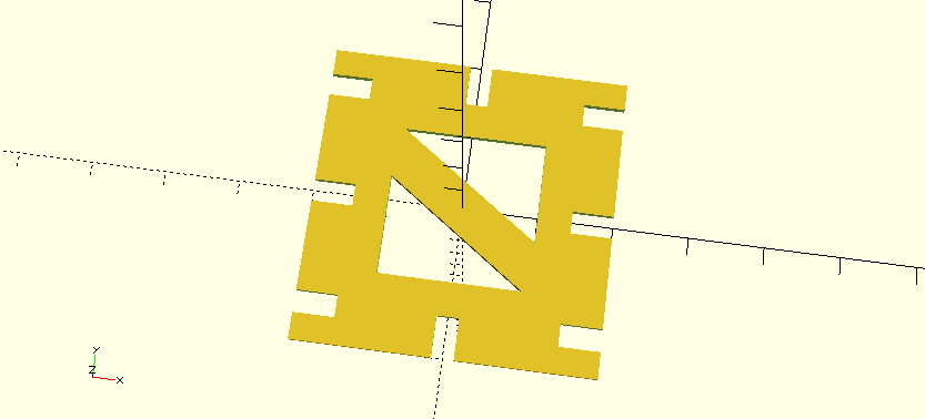
Union of tower face
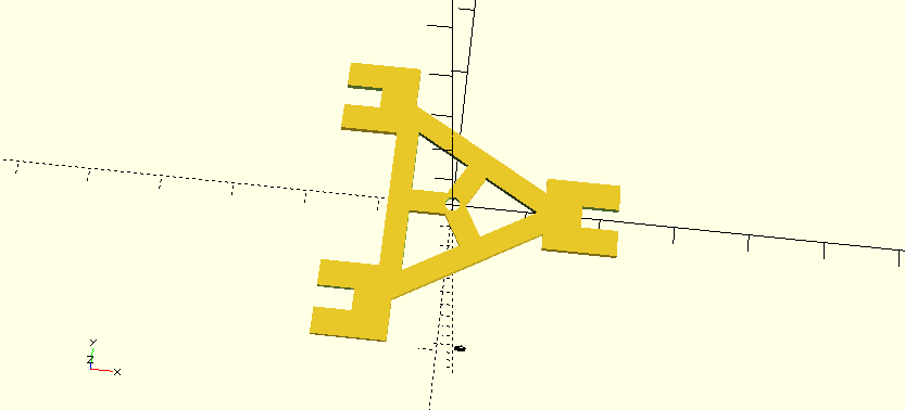
At the beginning of my union design, I had the idea to create a H union, but it can mantain the stability and not allow grow. So, the second approach was to create a T union, the advantages were so clear as it could combine three faces of tower up, down and lateral. This proposal were designed and developed in MDF of 3mm until we seek the final design. In the left image shows the final skecth of the design and the image belong here is the design in OpenSCAD. For more details can download the file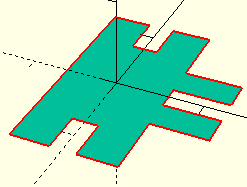
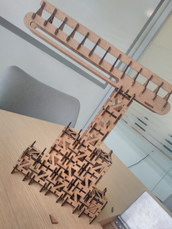
The tower was born!
The arm design
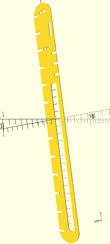
The idea to design the arm of crane was not scaled from original crane, we proposed our arm with specific dimensions without consider mechanical analysis. In the left image represents the skecth of our arm, after one prototyping we adjusted the measure as the rail width with 8 mm and the unions of the parallel supports. With OpenSCAD was easy design repetition patterns as the unions in the button of each support. The middle image was the support the both sides of the arm considering we use a triangle base, and right image is the up supporting arm. You can download the files of rail support and top support.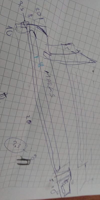
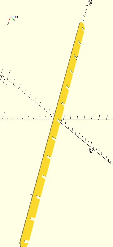
The first image in this row is a middle design until to test the structure and conclude with OpenSCAD model as it shows in the right image. You can download the source file here
First approach complete!
This approach was concluded but I wanted to create the rotation in Z axis. So I took my next challenge "rotation in Z axis".
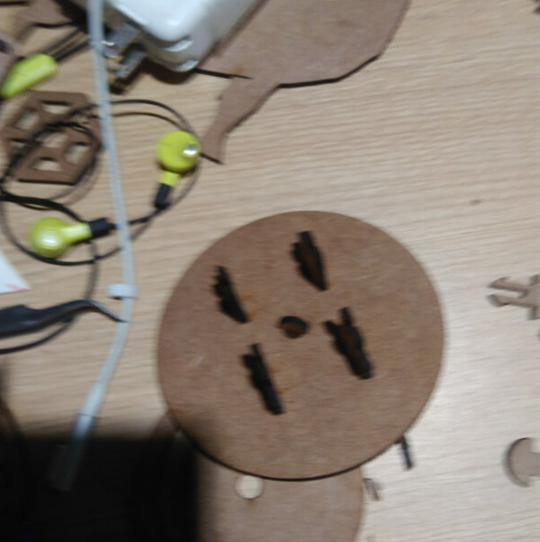
Base rotation design
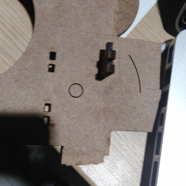
The right image represents the first approach to create a base that allows rotation in Z axis. The original idea only considered a rotation of 180 degrees, but it was limited. Then we thought in two platform united with rotate piece, where one of these were the base with elements that allows rotations. These elements are presented in images below this paragraph.
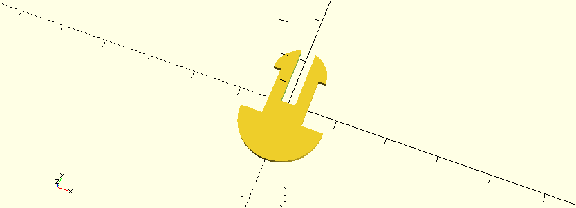
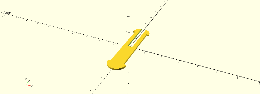
Base rotation design
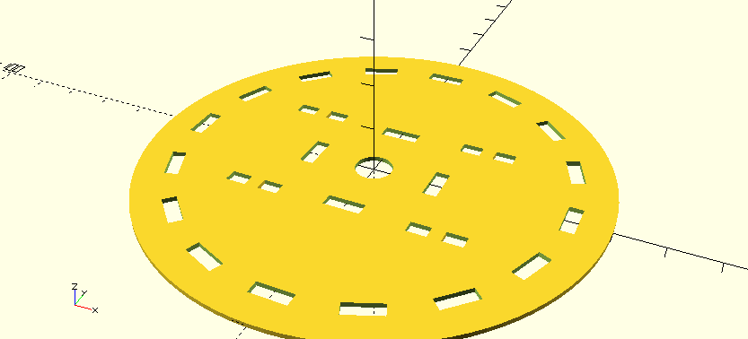
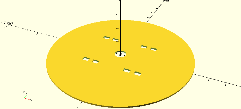
Testing the base design
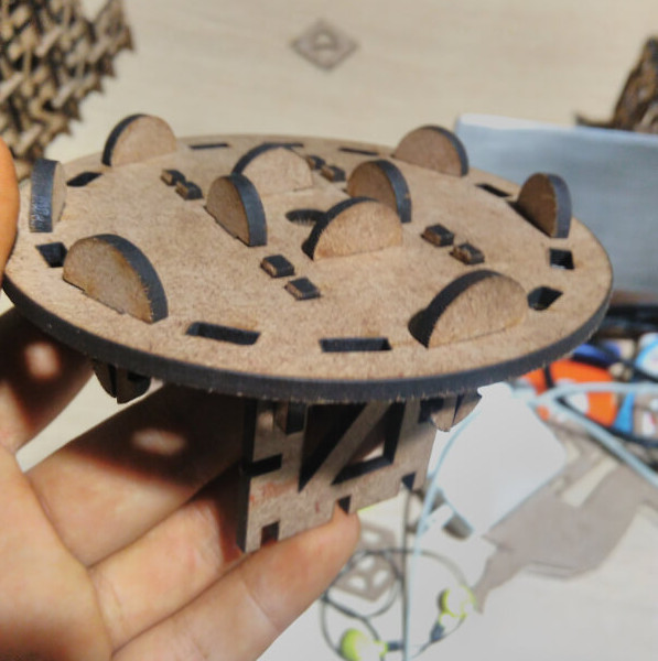
Finally!
Vinylcutter
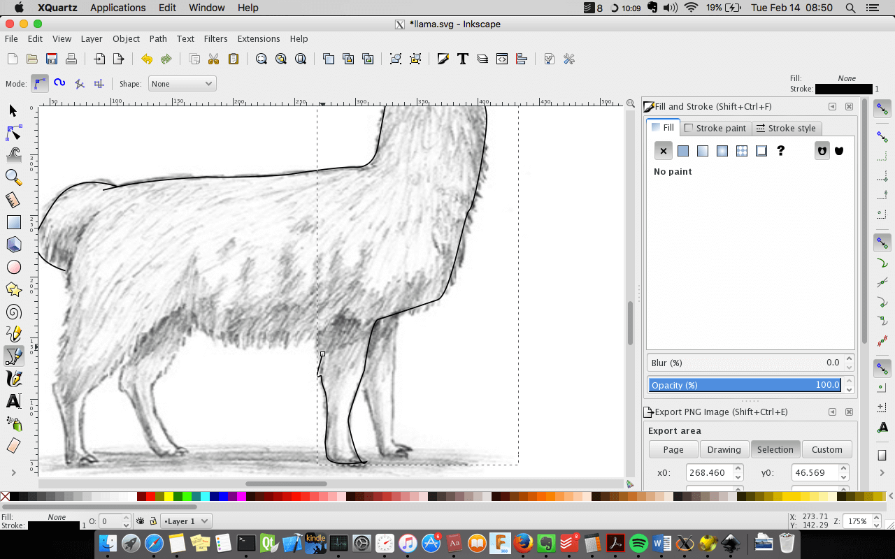
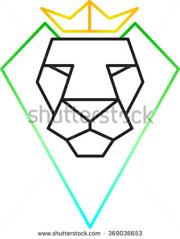
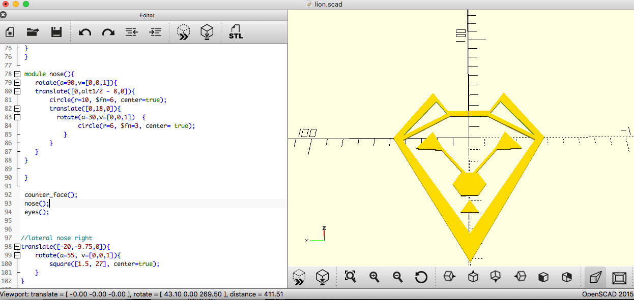
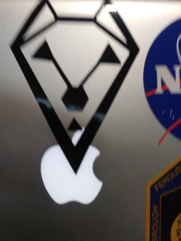
My original idea was created a logo like a lion wire. I took a photo from google images as it showed, but I did not know the measure of that. So that I took the measures of a logo on my computer.
With its measures I drawn in Openscad, the first challenge was created a irregular shape. Therefore, I thought that the complex is the plus of simple things. I divided the images in triangles. After coding the edge, and I could see a llama and not a lion shape. With the idea to change the logo, I got this llama based on the combinations of simple polygons and triangles.
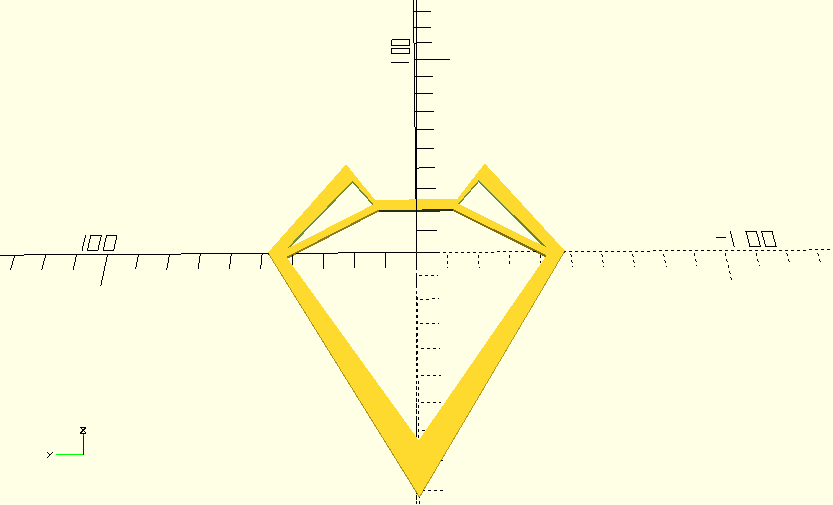

This iteration was awesome and we could draw a original logo based on two ideas. The final design in OpenScad can download in this link .
- Export to svg file from the design in OpenScad.
- Open the terminal and write the command fab
- Fabmodules launch a menu of input and output. We selected png as input and output vynil cutter machine.
- In the new GUI, we selected vynil option and load the PNG file to make a path
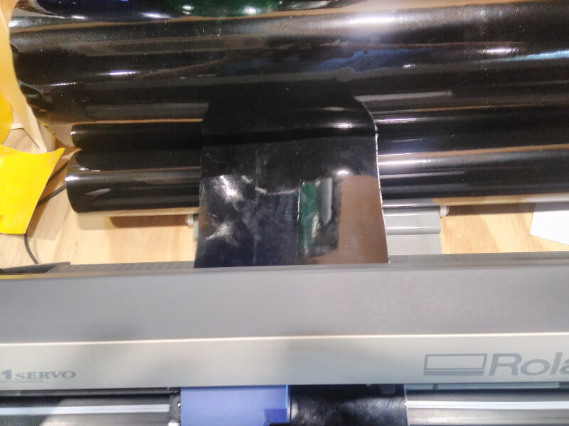
- Put our piece of material in the paper feeding unit.
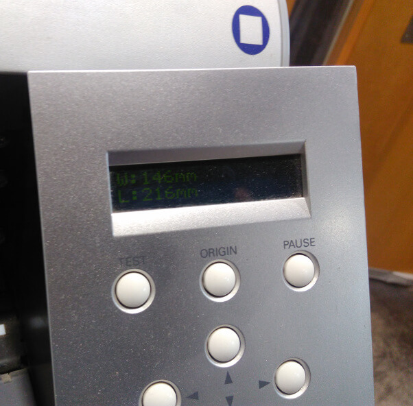
- In the menu of Roland we select piece, so the machine measures the sheat.
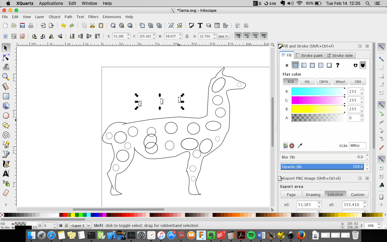
- In the program we load the png image. This image was pre-processed with Inkscape to add background.
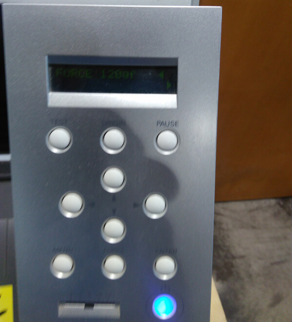
- Check the original force in the machine to put in the GUI program.
- Press make camm and send it buttons.
- It's done!
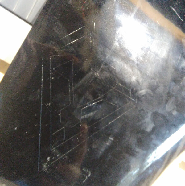
The logo was put in my computer and the problem was that it does not shape without supports.
Project
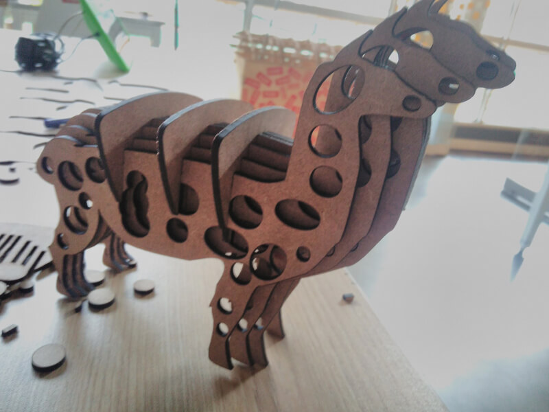
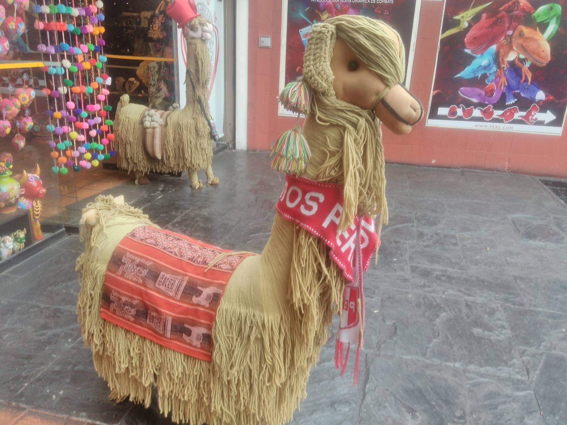
A sunday when I was walking in Lima I found a Handicraft store focus in Peruvian art and related. The most curious toy was a big llama in the front of this company. It has around 140 centimenters of height, and I was so fascinanted by its shape, textures and simplicity.
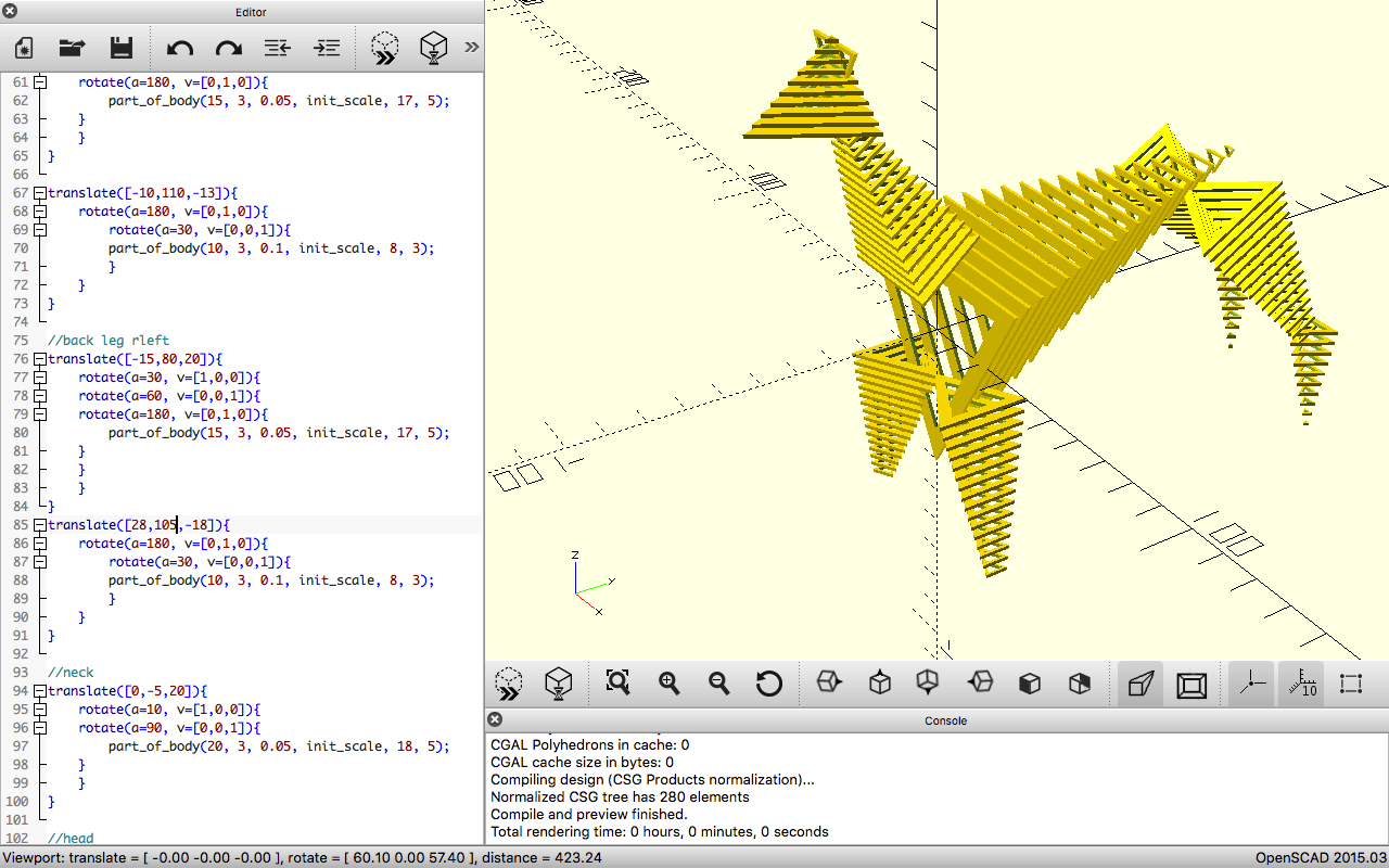
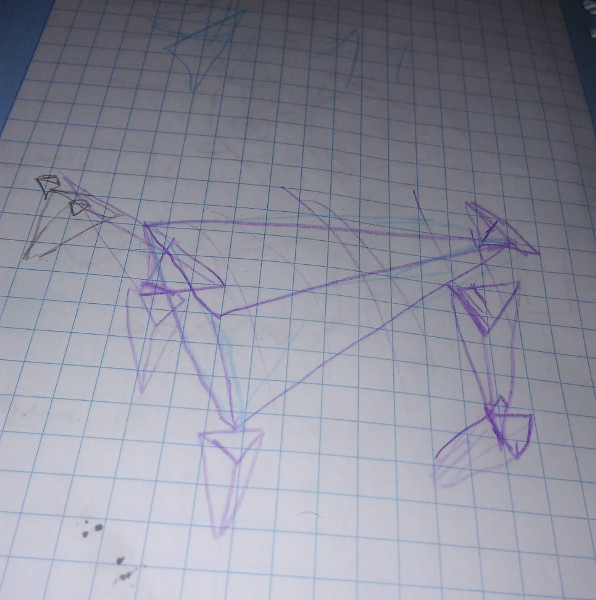
The beginning idea was to make a llama like the original but I considered that we can assemble any object, this hipotesis is true if I try to use a triangular mesh to represent object 3D. So that we created a first approach with triangles in OpenSCAD, in this program we only create a simple concentric triangle. To create the shape of the llama we iterate the triangles through X and Y axis, and scale these axis. Additionally, we rotated the triangles. The source file is here.
Second approach
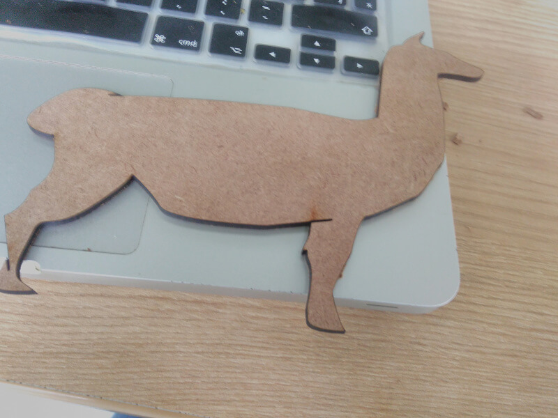
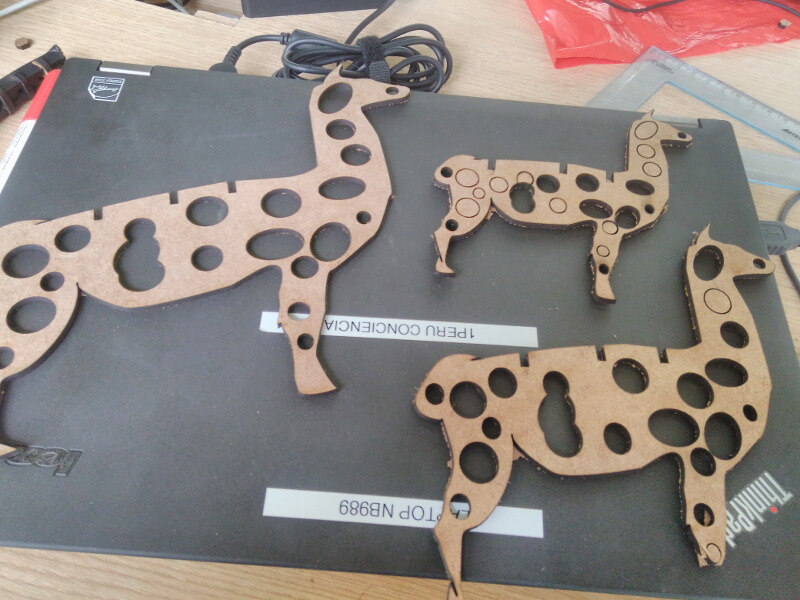
The first was good but we would have problem if we had implement this. The main reason was the supports to keep the stability of the llama body. Therefore we change the idea by create a simple lateral view of llama, Inkscape helped for this purpose. The body was build by consecutives sheet of MDF llama each sheet was scaled with differents measure. To unify the sheets we create a card where it can put all elements. The original llama can download here and the scale 2 and 4. The mount of sheets can download here, this file depend of this stl file