Electronics Design
The assigment for this week:
- Redraw the echo hello-world board
- Add (at least) a button and LED (with current-limiting resistor)
- check the design rules, make it, and test it
- extra credit: simulate its operation.
- extra credit: measure its operation.
My vision in this assigment was:
- Take a tutorial of Eagle.
- Draw the same circuit of the current lecture.
- Add the push button to current design
- Program the circuit using our FabISP
- I will try to complete the extra credits if I have time left.
Just do it!
The first I have learned using EAGLE thrugh reading the tutorial. So we procedded to do. Firstly, we reply the original scheme in Eagle. The steps are detailed following:
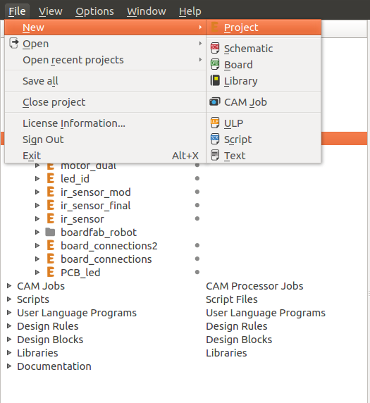
Step 1: Create new project
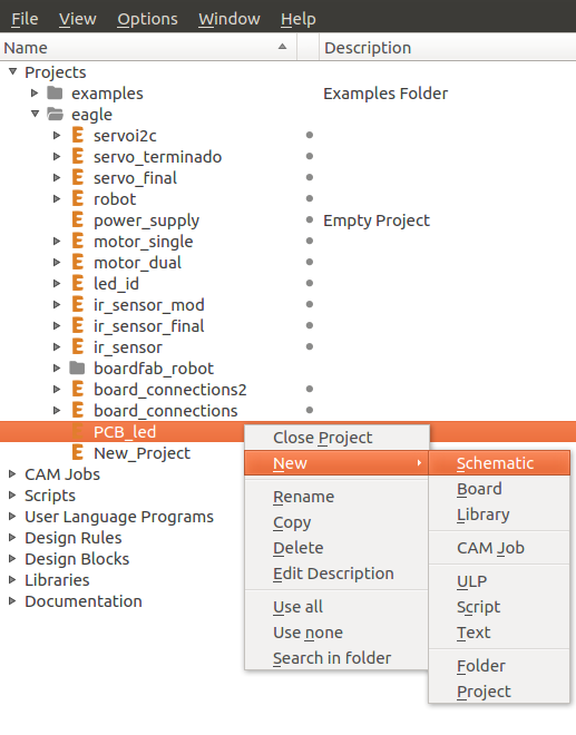
Step 2: Create a new schematic file in current project
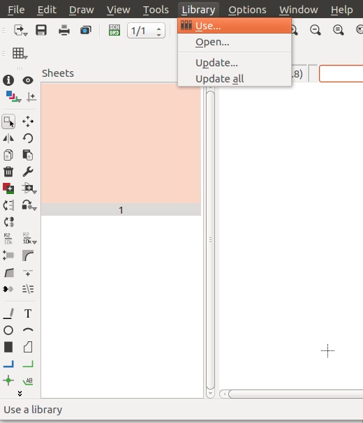
Step 3: Add fab.lbr library to the project
Step 4.1: search fab.lbr in the system
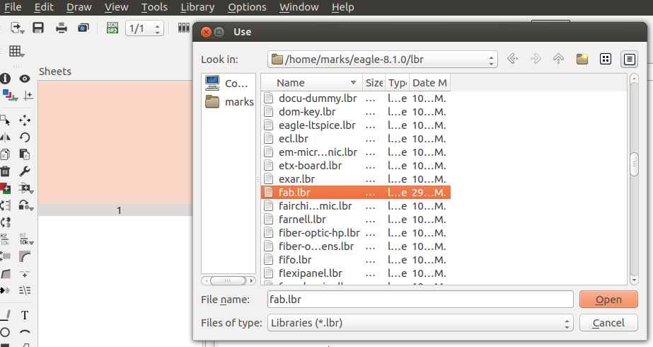
Step 5: Search fab library
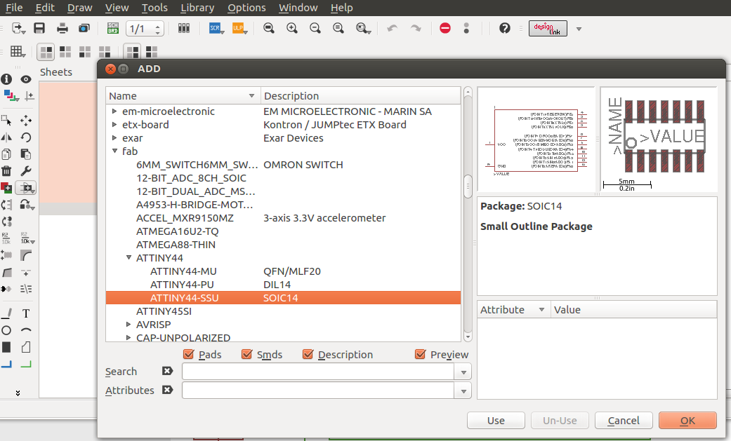
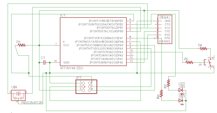
Step 6: Add the electronic components to schematic file
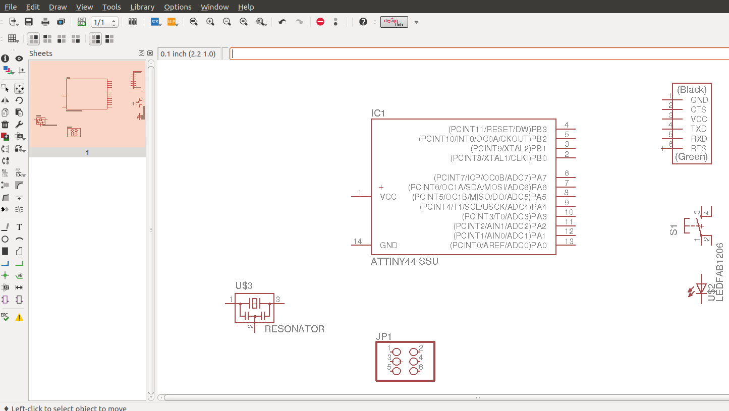
Step 7: Connect the components
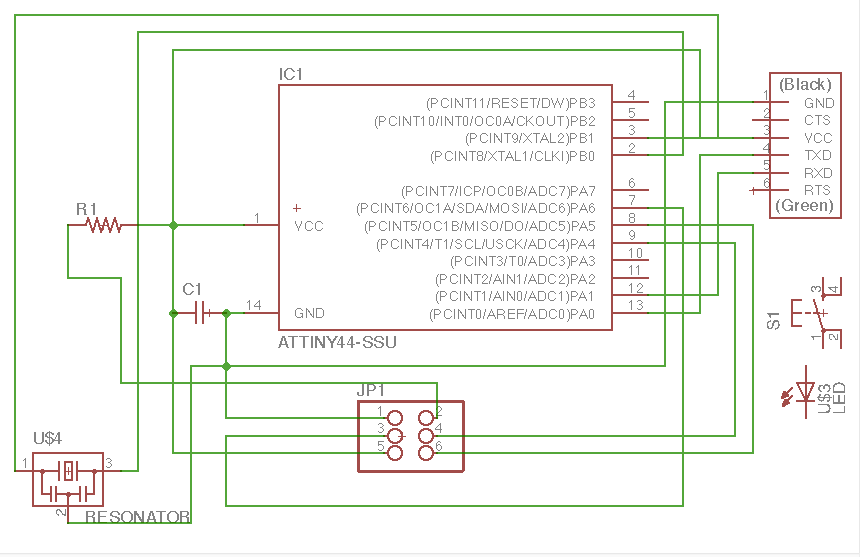
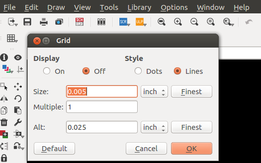
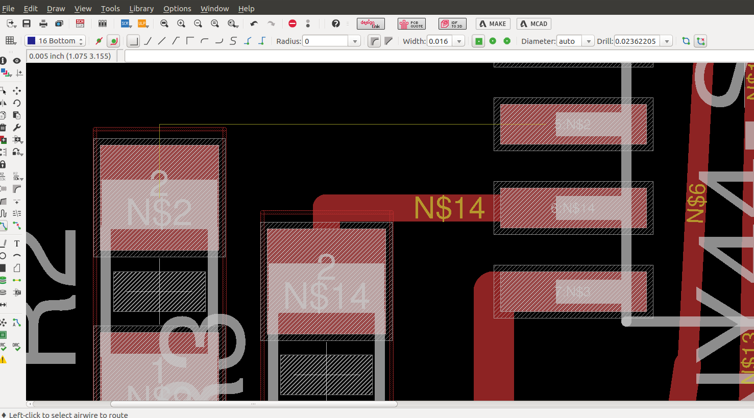
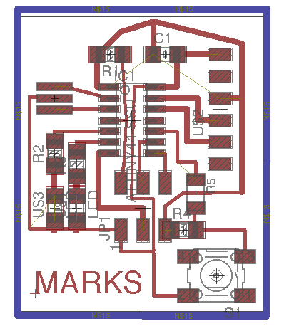
Step 7.1: Create a board file from schematic with button sch/br. And configure the grid settings with
Step 8: Draw lines over the line connection. The width line is 0.016"
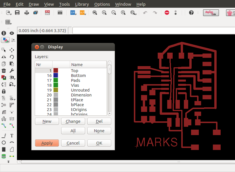
Step 9: Select the colour layers to display to export the current view. File >> Export >> Image
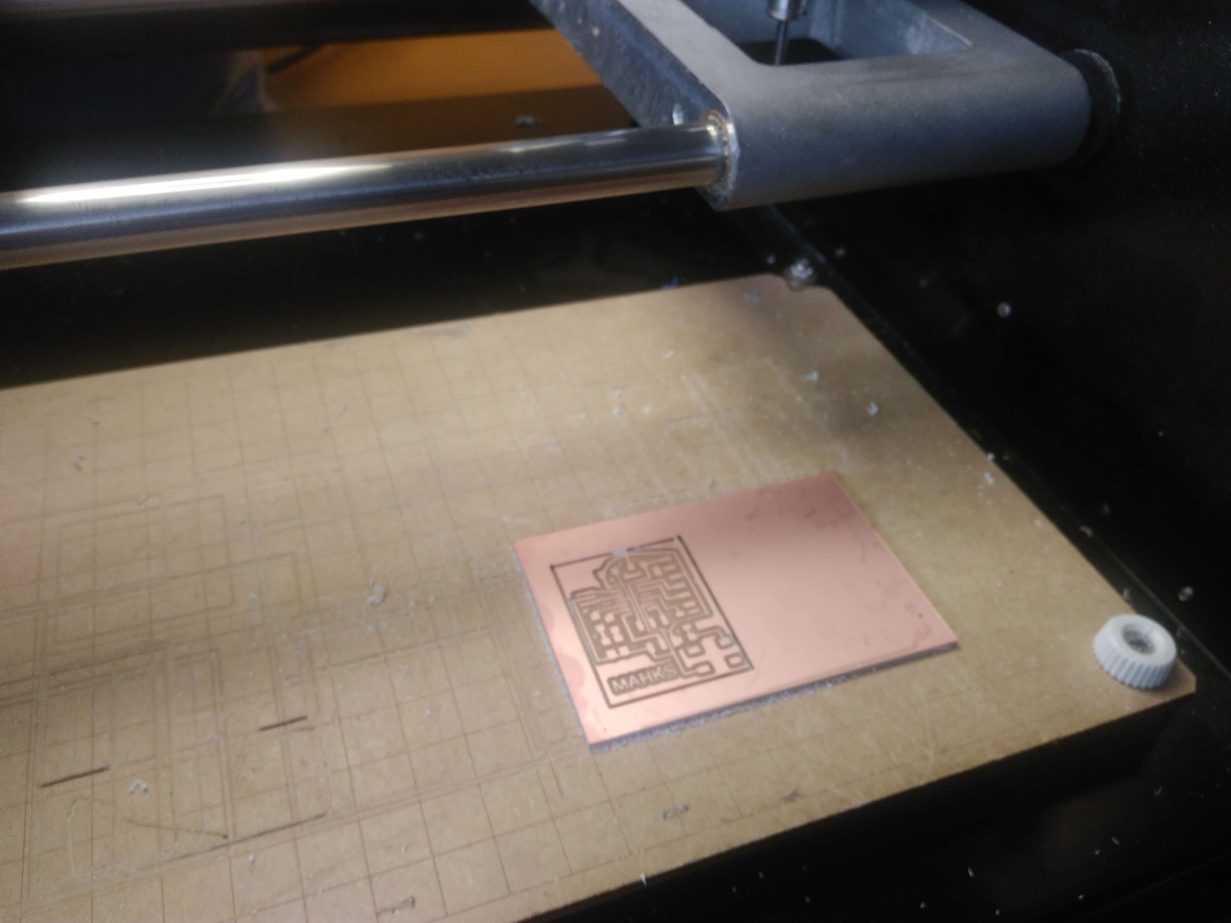
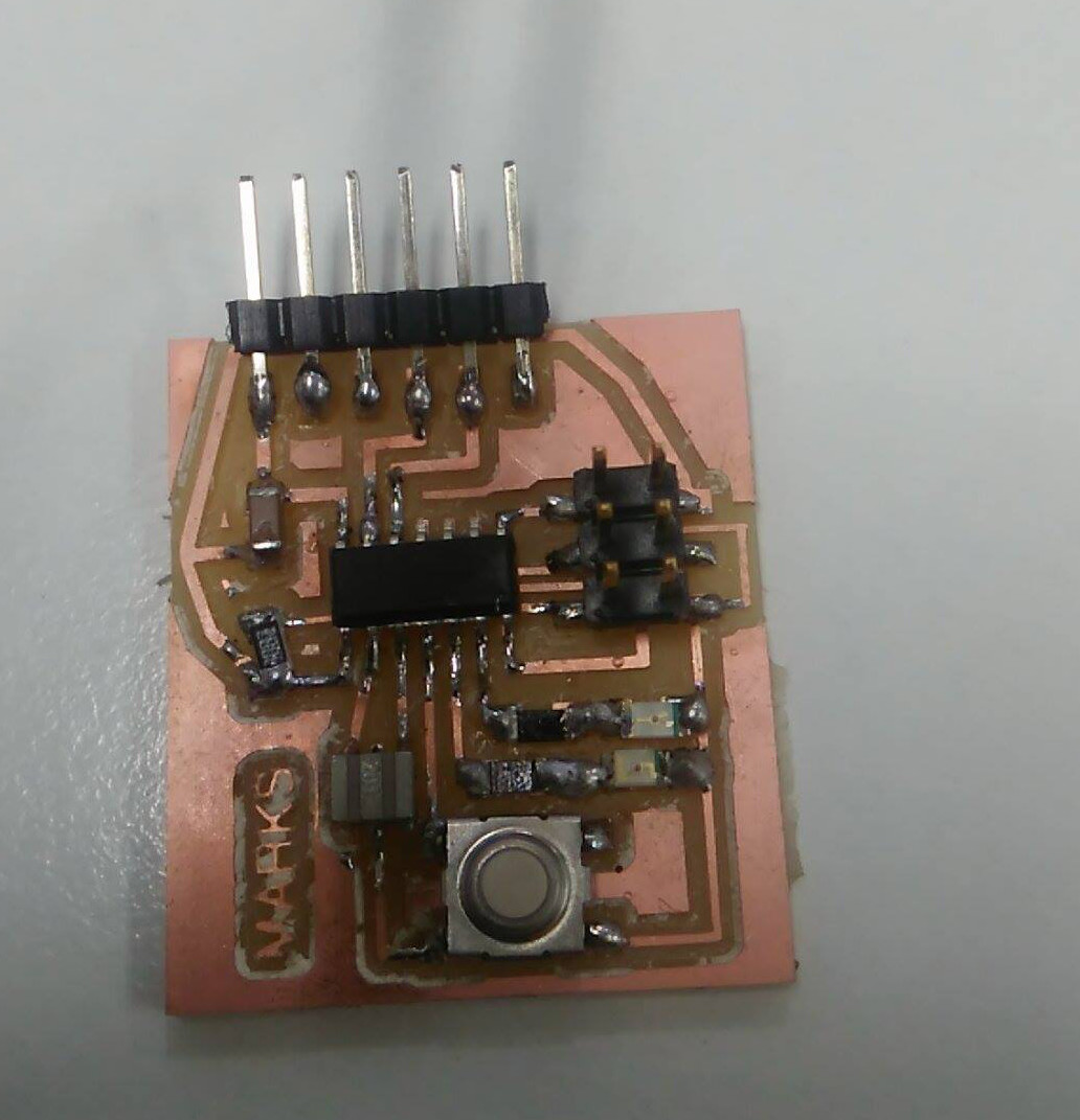
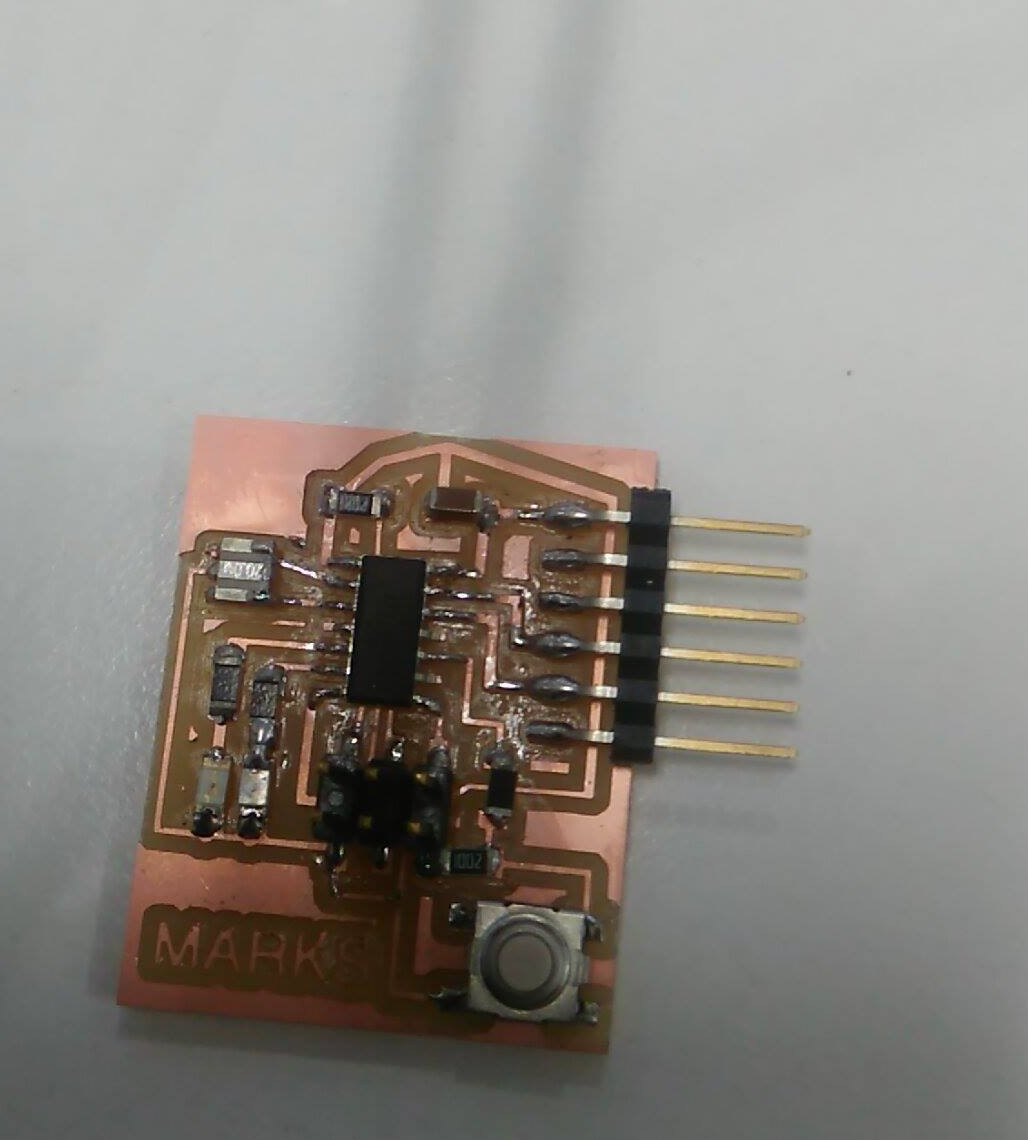
Finally
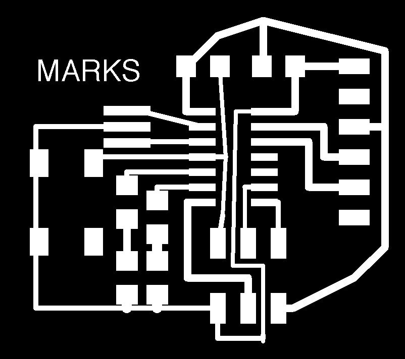

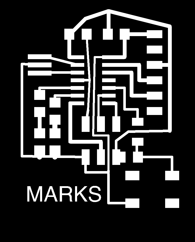
The parameters used in the grid was 0.005", the width of cooper track that I considered was different in the border I consider 0.024", line parallels with 0.016" and the line wich passing under the chip has 0.012". In the next assigments I am going to use a unique size. The design was completed to export in 600 dpi with monochrome color, but we invert the color to use in Roland MDX.20. Finally, the traces image cutted in Roland machine and soldering elements.
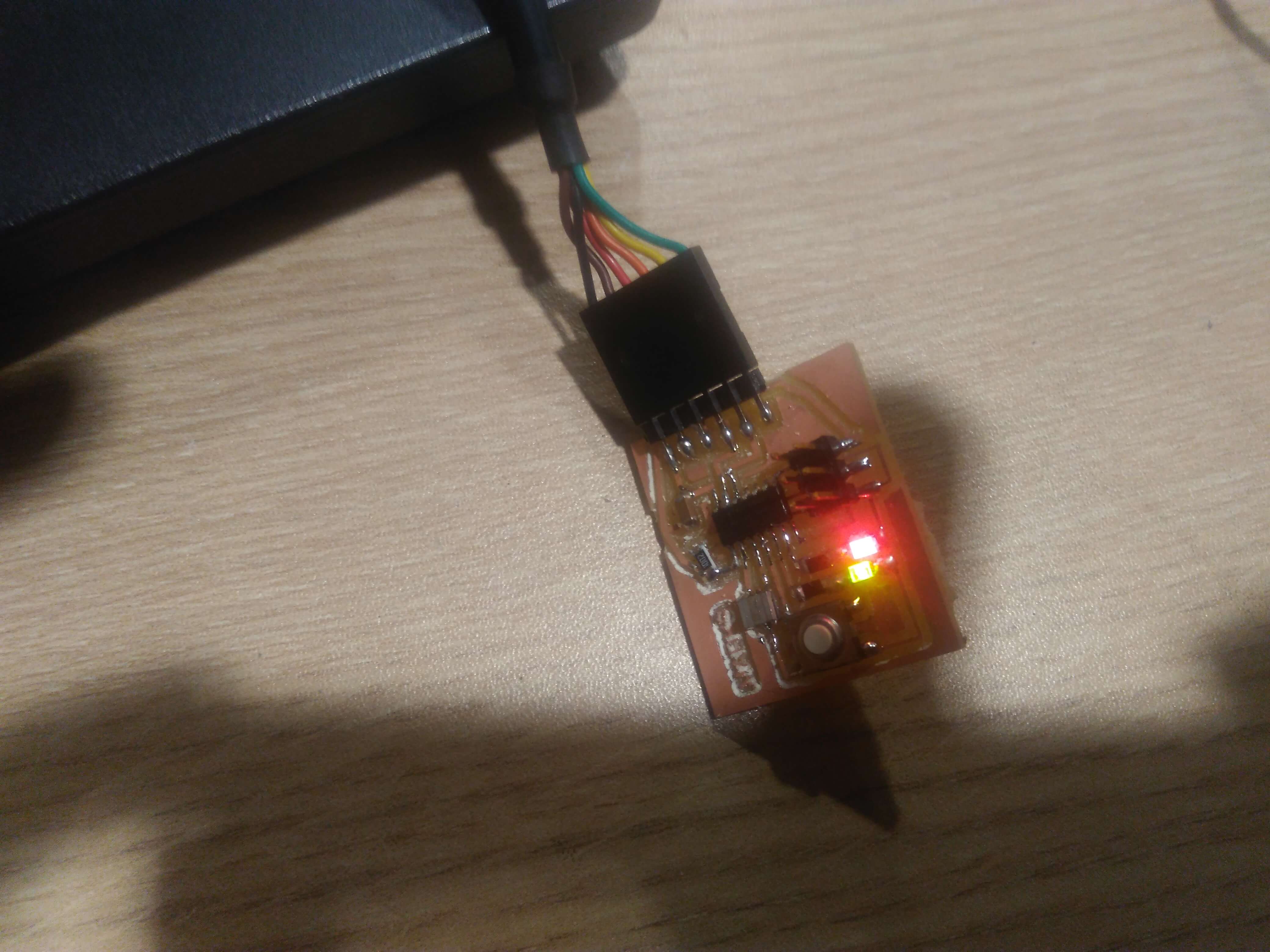
Programming the PCB
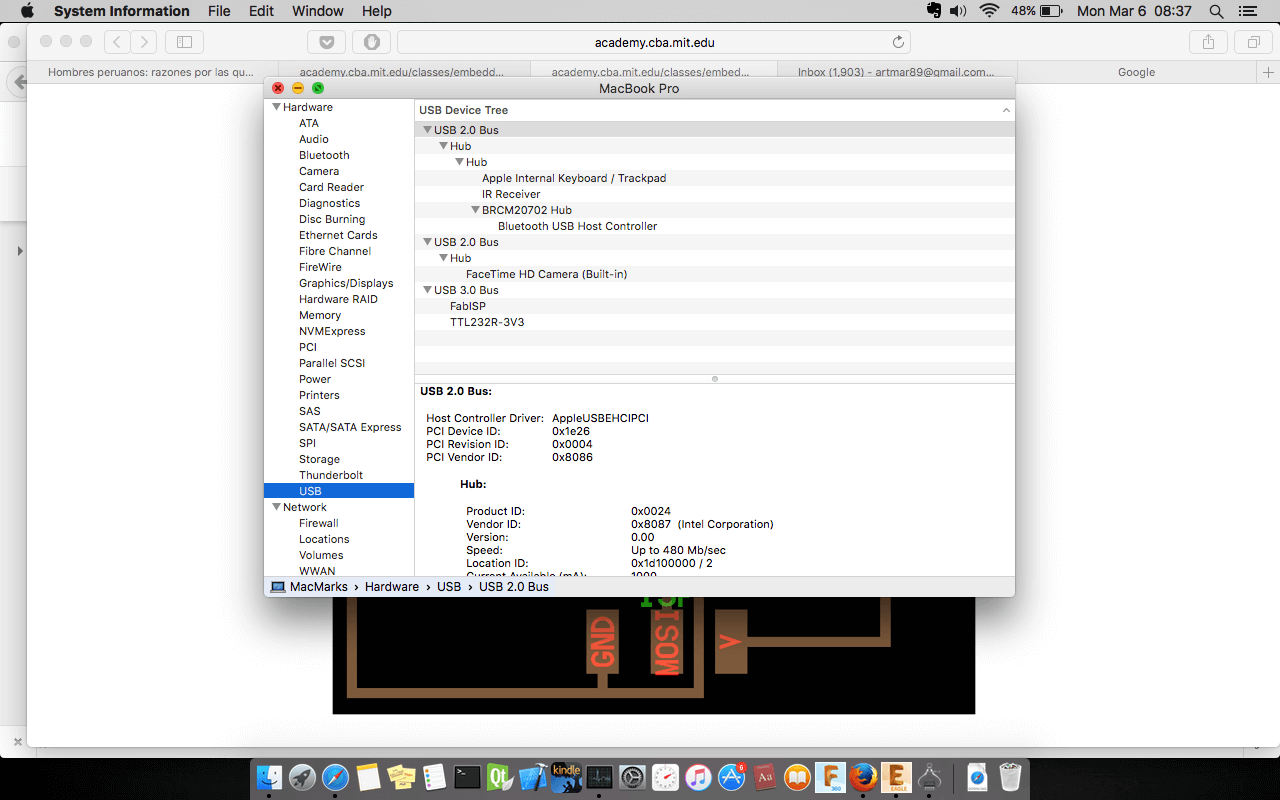
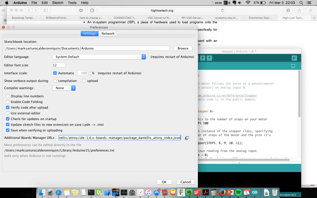
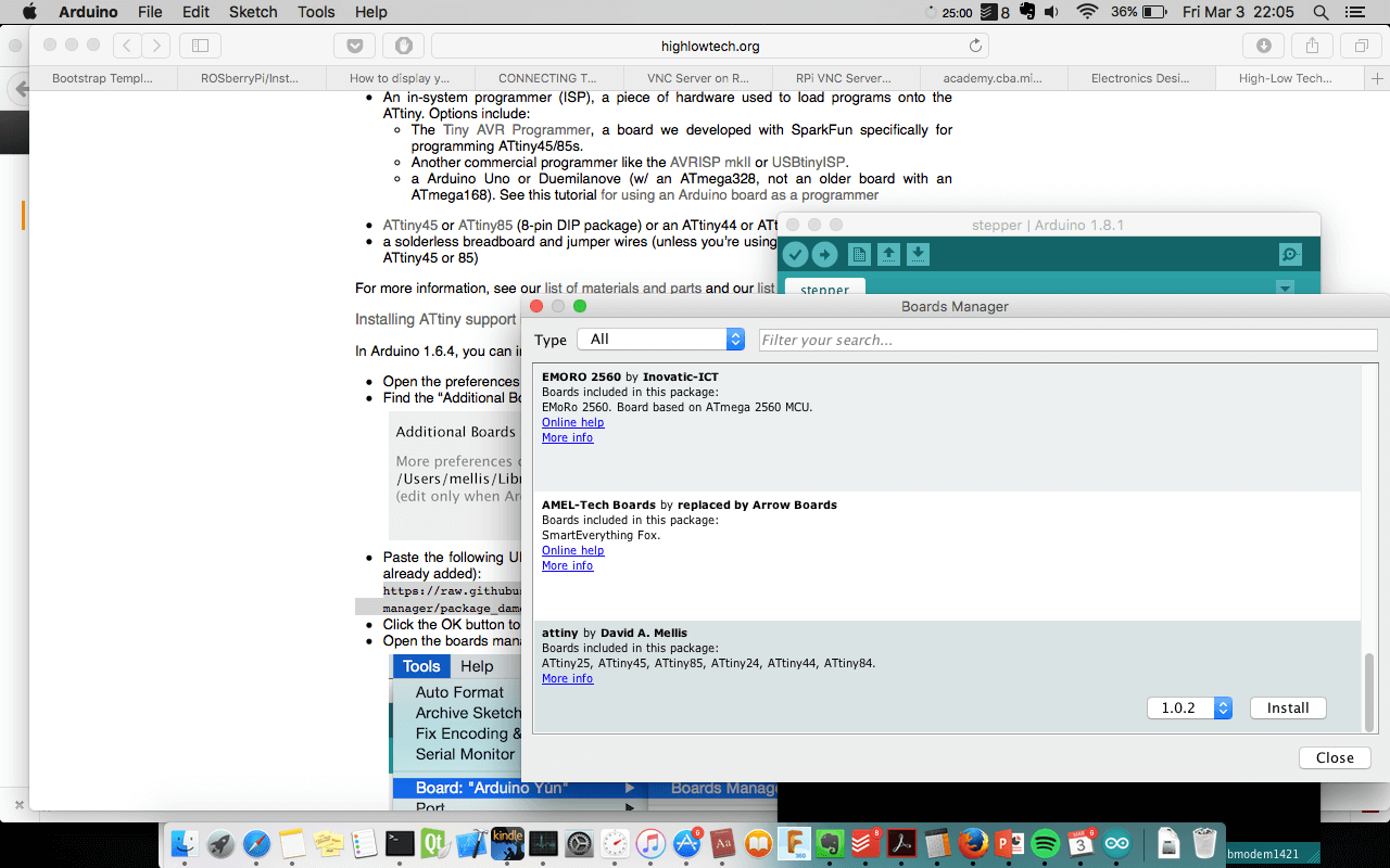
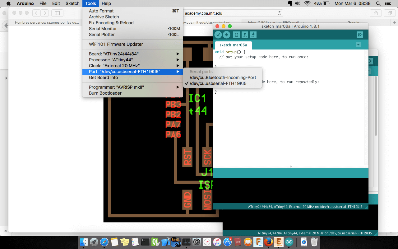
Before programming our PCB we have configure the environment in my Macbook. We have installed the FTDI wire with this driver. In order to program the chip we verify the systems when they are connecting in the laptop, in Os X we do not need install a driver for fabISP. After checking the devices are ok, we read the Attiny tutorial. So that we setup the Arduino 1.8.1 in my computer. In preference of the Arduino IDE we add the URL https://raw.githubusercontent.com/damellis/attiny/ide-1.6.x-boards-manager/package_damellis_attiny_index.json to put additional board in the system. In the menu Tools >> Board , we open board manager and find the attiny package to install.
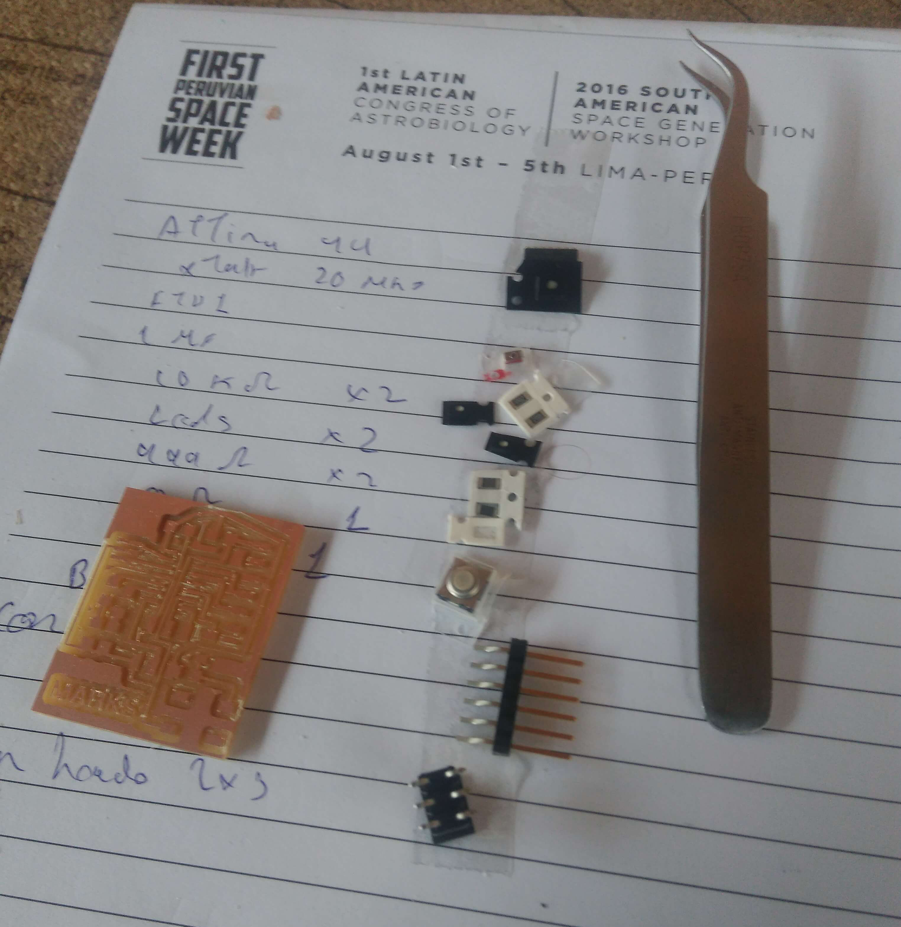
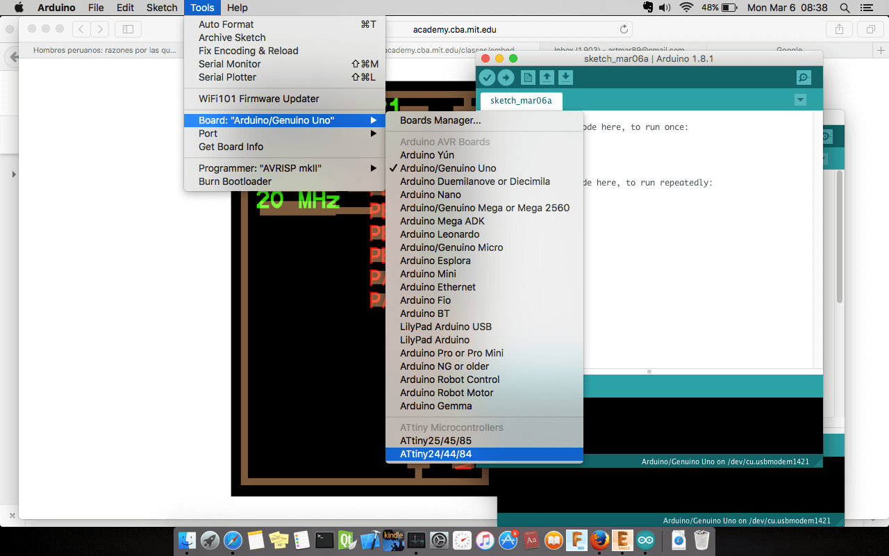
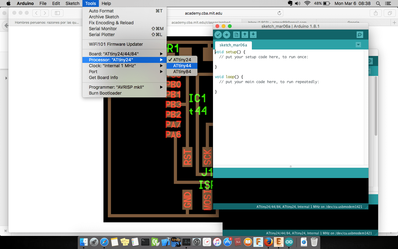
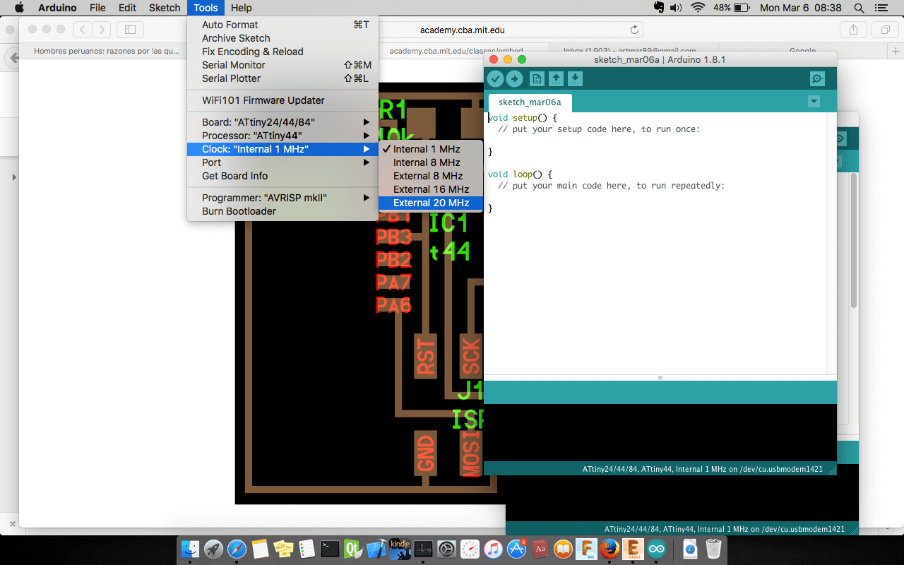
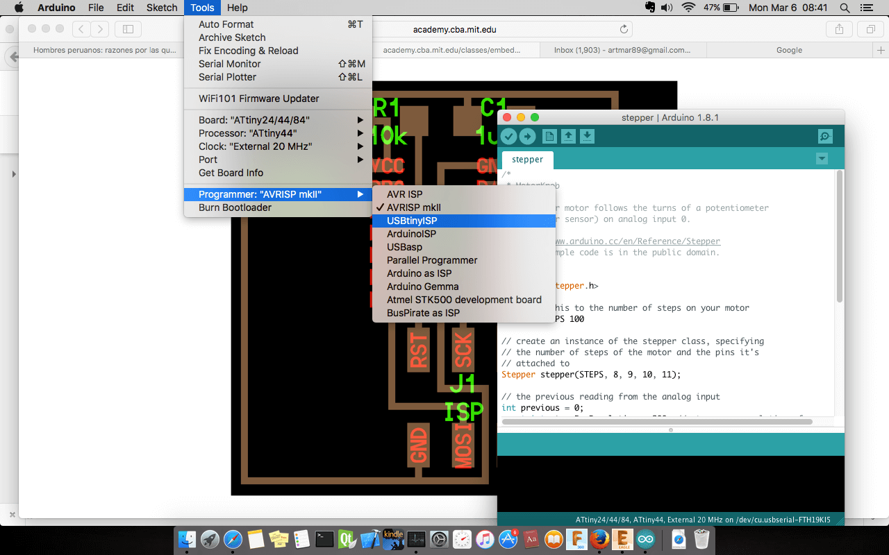
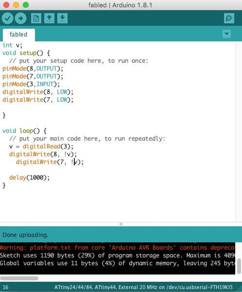
We have choosen the correct parameters according the elements that was designed. The parameters are:
- Board: ATtiny 24/44/84
- Processor: ATtiny 44/li>
- Clock: Internal 20Mhz
- Port: FTDI port
- Programmer: USBTinyISP
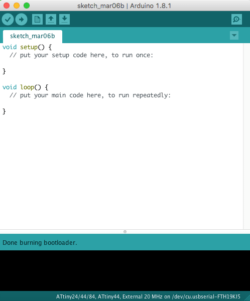
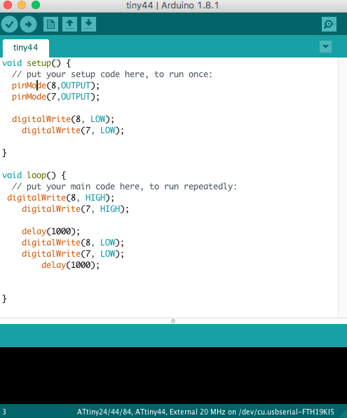
Now we burn the bootleader. The output message was correct, "we did it!!!, I said". While programming the board we found a little issue the pin 4 is reset and we can not change to use as normal pin OMG!!. But I have continued coding the board, so we can turn on the leds, but we can not read the pin 4 from the source code. When we press the button, the circuit will reset.

Conclusions
My conclusions are: