Computer-controlled machining
The assigment for this week is made something big. I though to create a bookshelf chair So for completing that we divided in three parts:
- Testing shopbot in group
- Test with my design
- Make my design
Testing shopbot
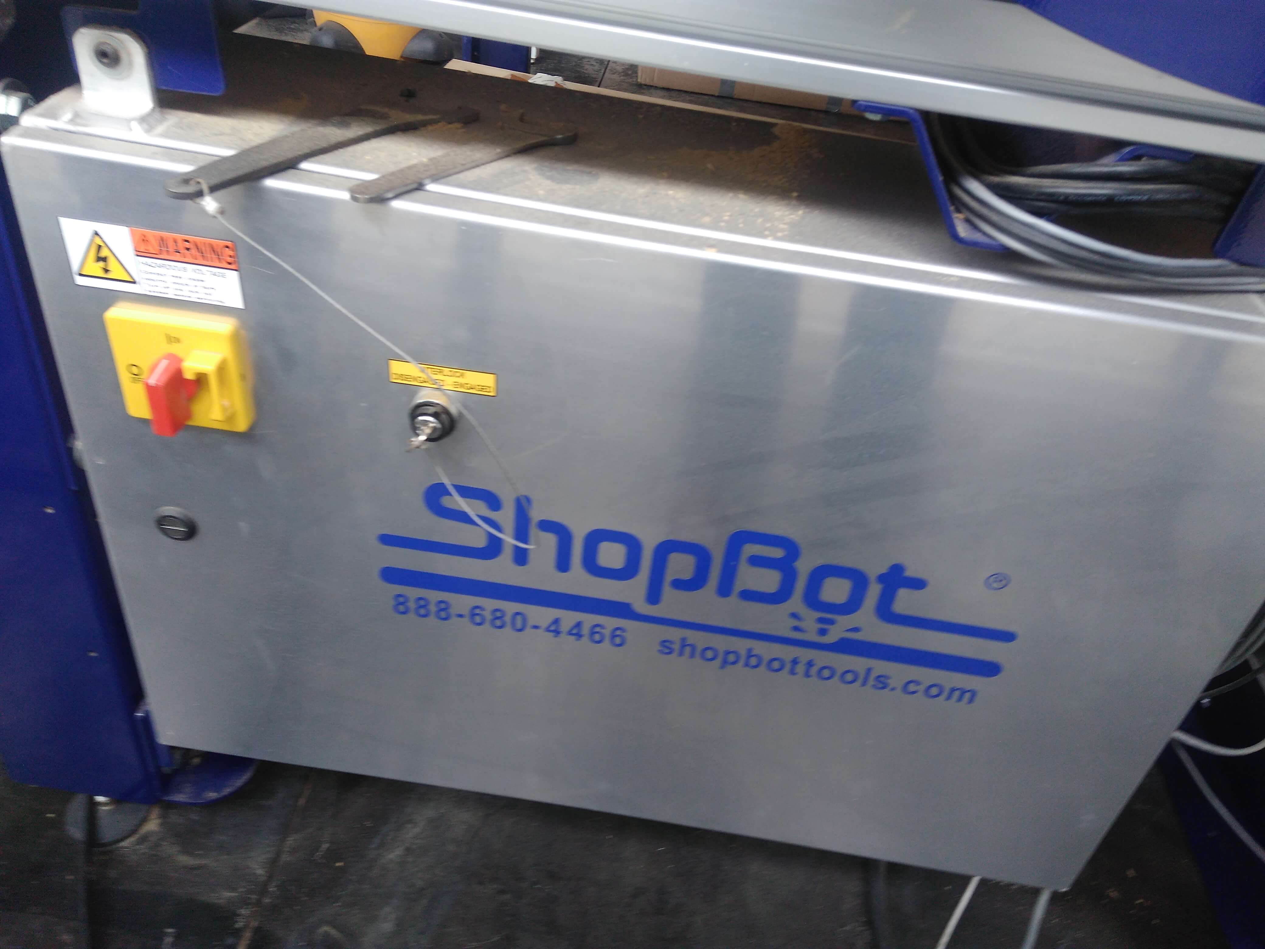
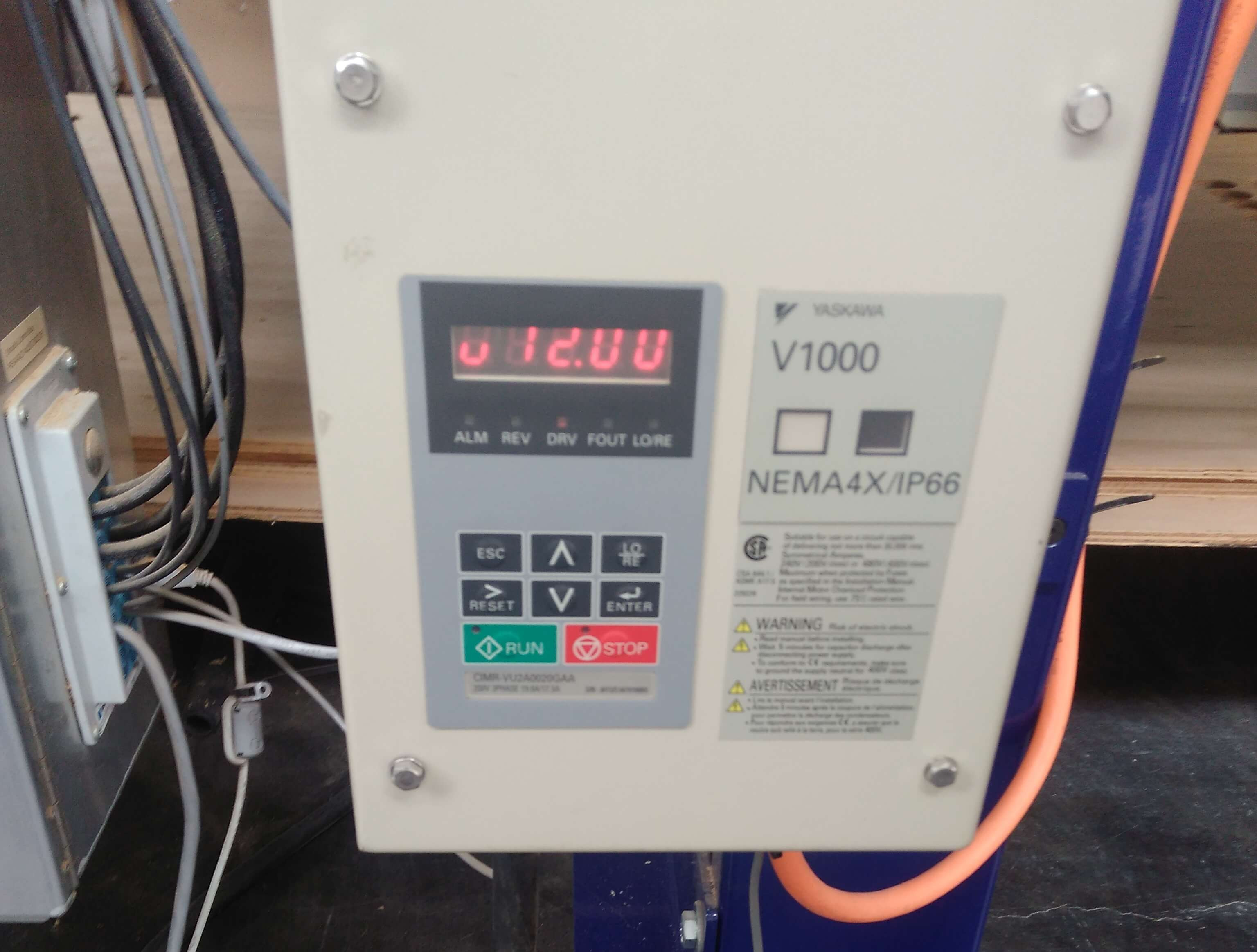
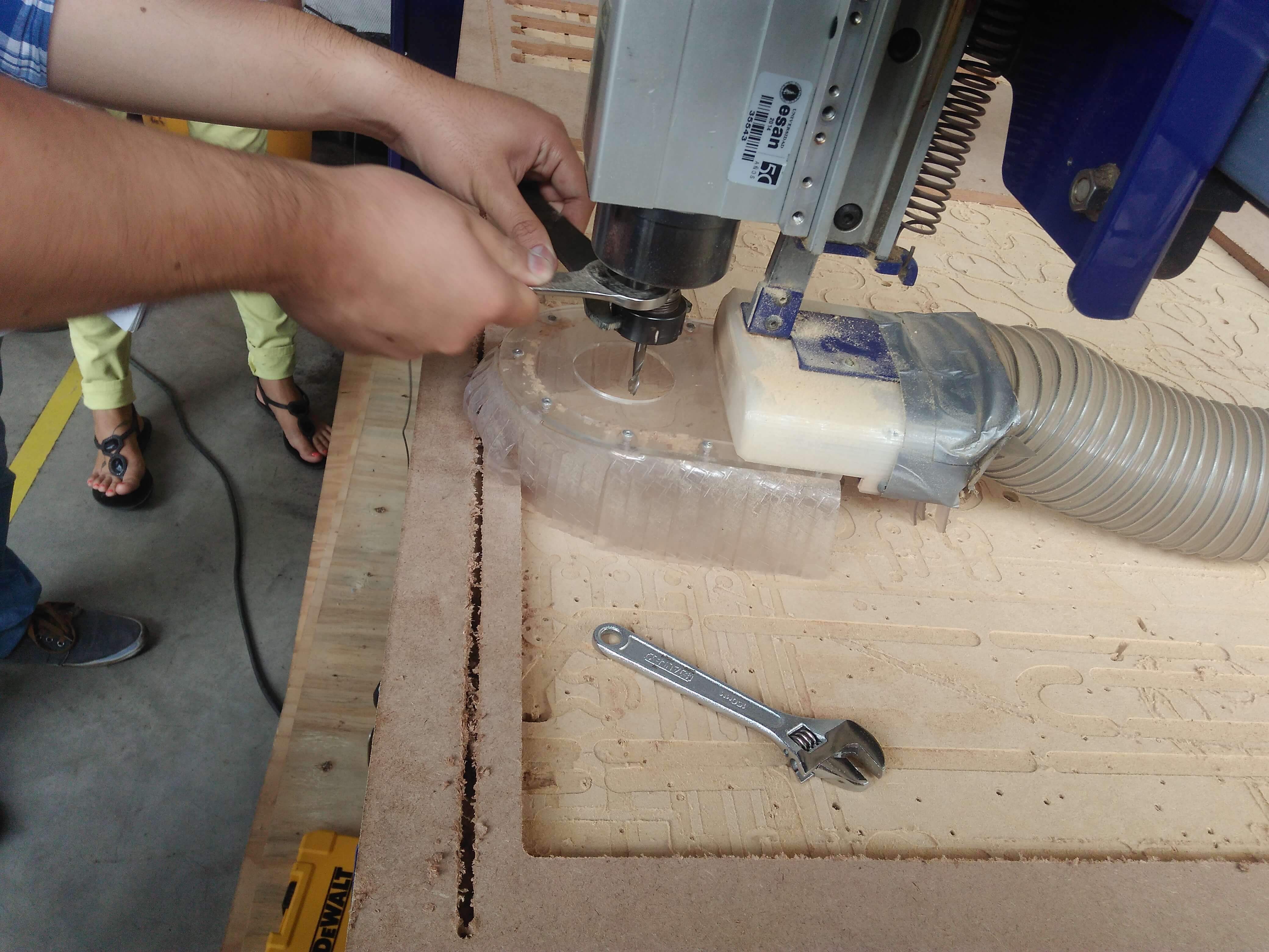
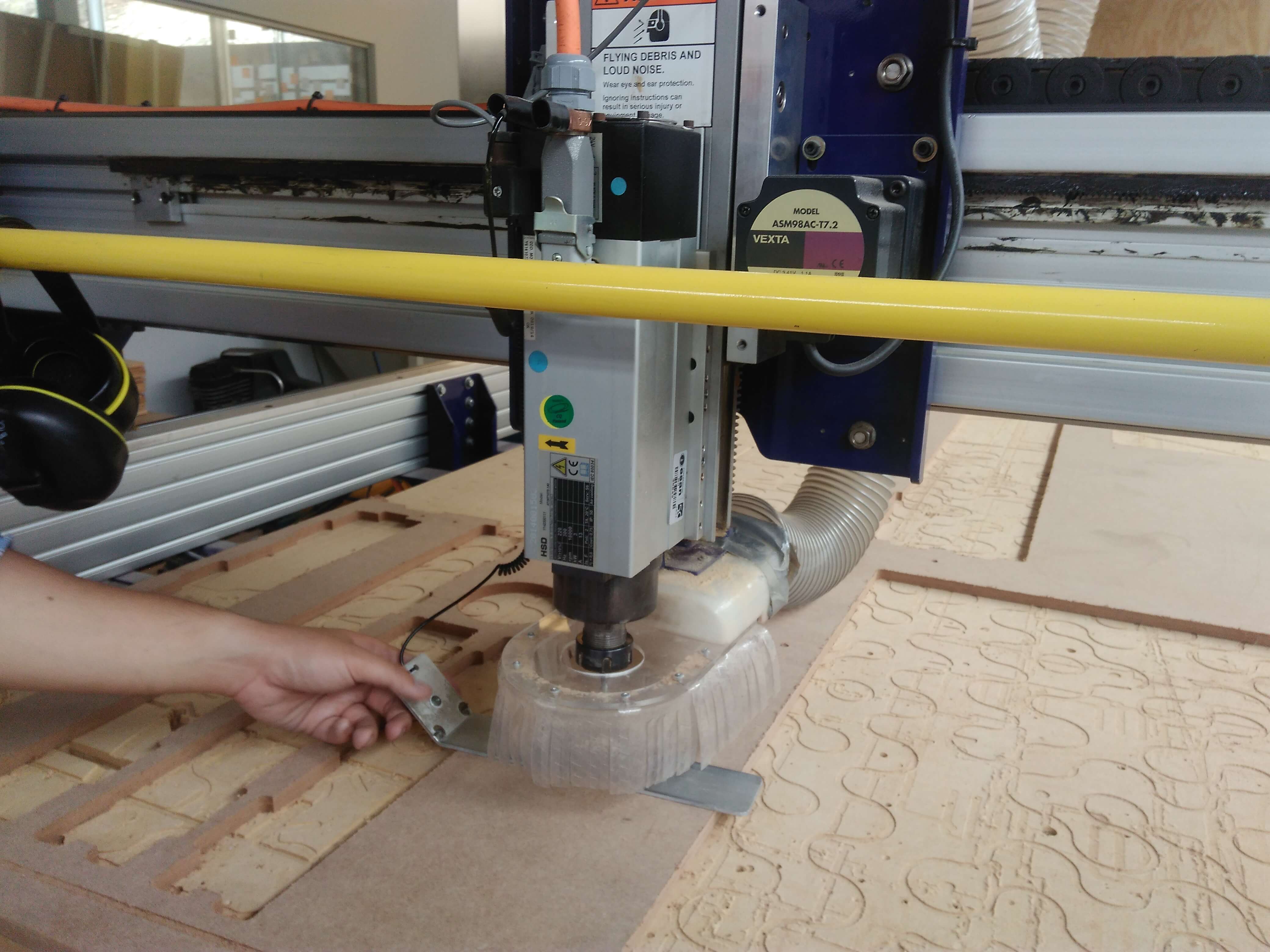
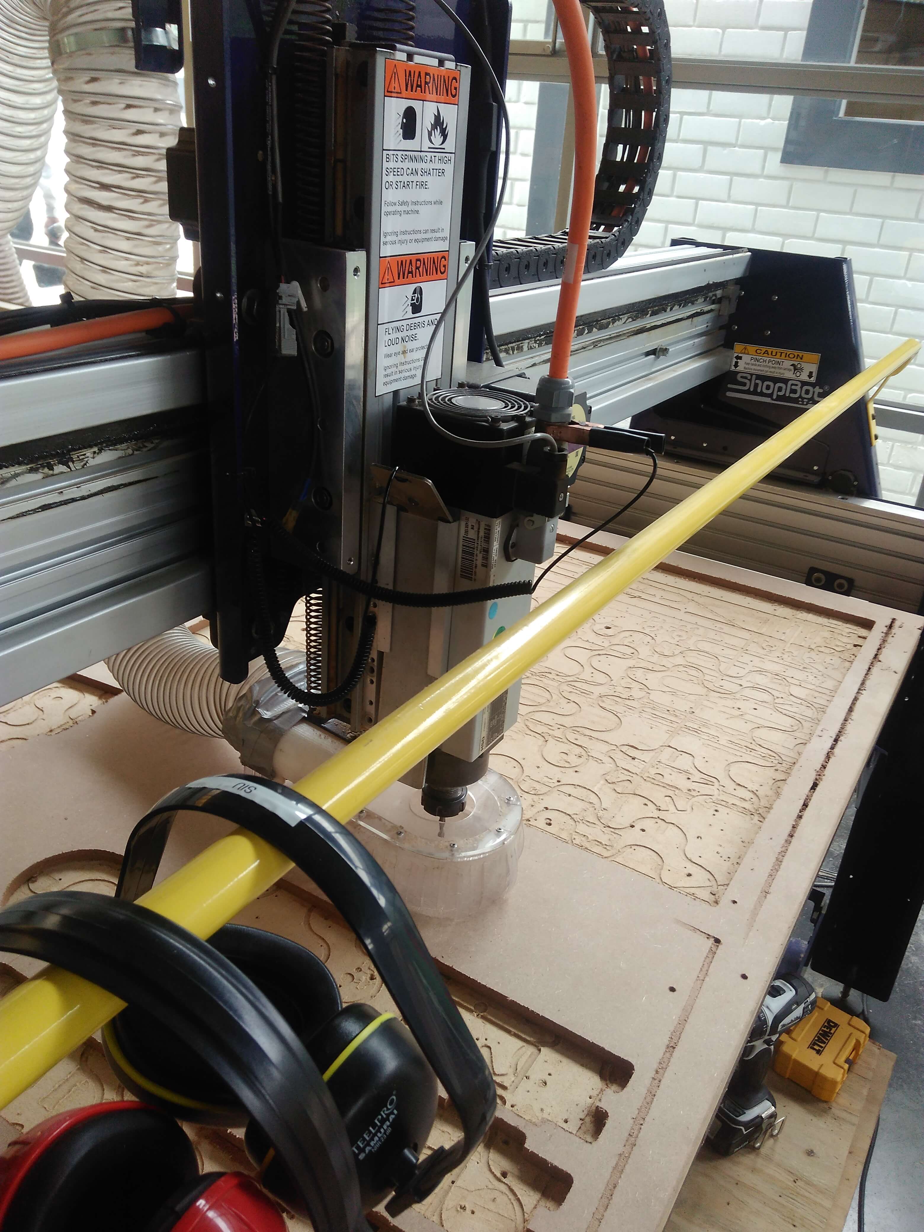
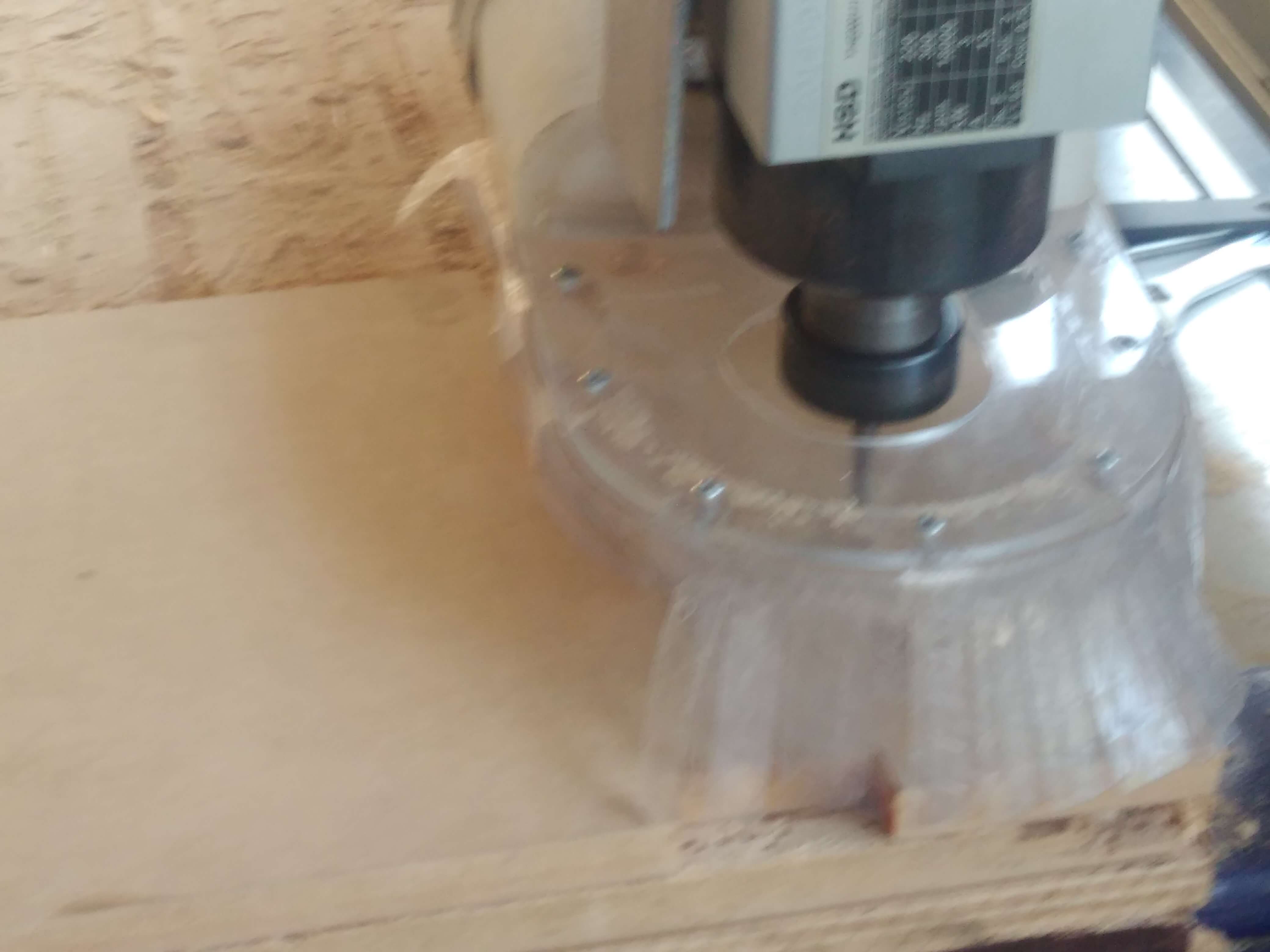
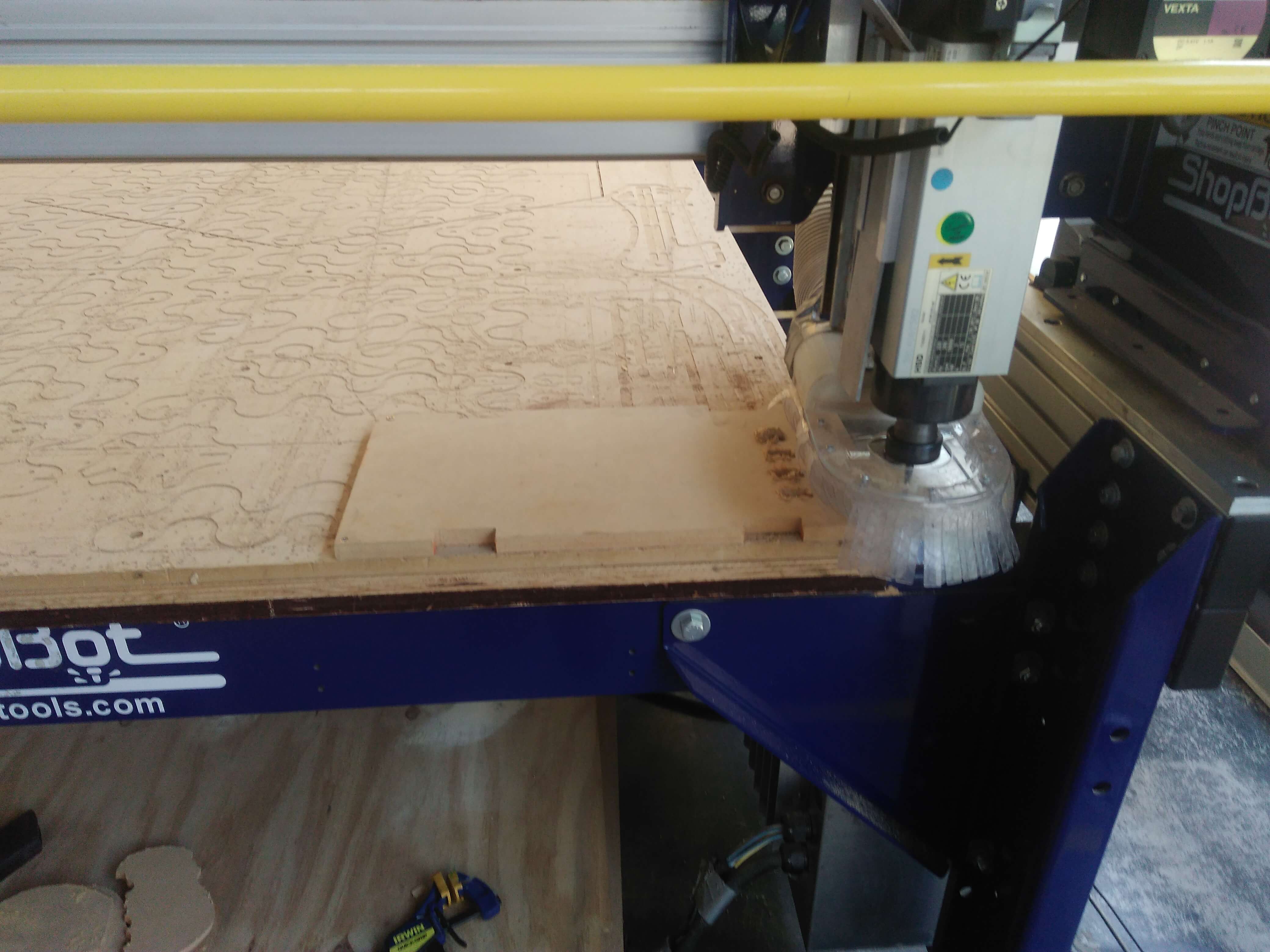
My team and I have trainned by local instructor to use a Shopbot. The first thing that he said was turn on the swithc and unlock the machine with the key. So we should verify the led speed panel. The machine chuck should for adjusting the drill cut up. With the MDF on the table which holds with crews in its corners. The next step was calibrated the axis Z and XY, the first we move the head in the middle and we did calibrate with the plate and alligator.
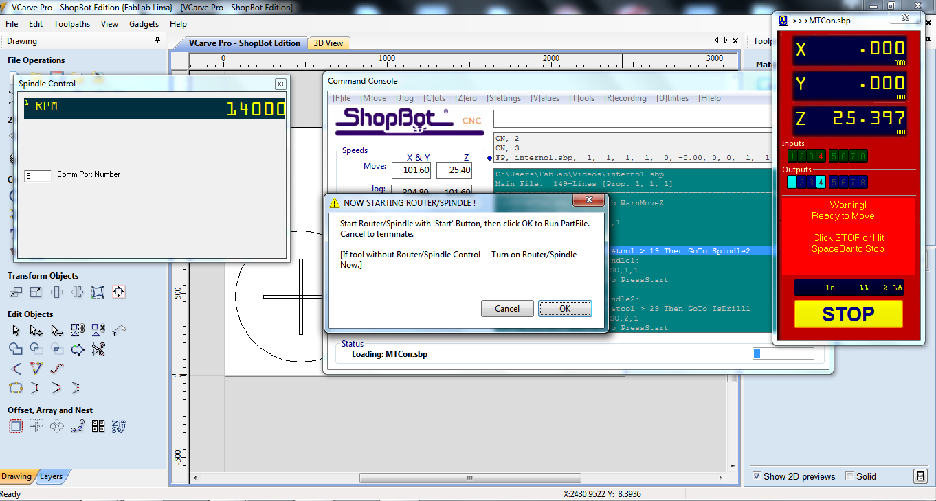
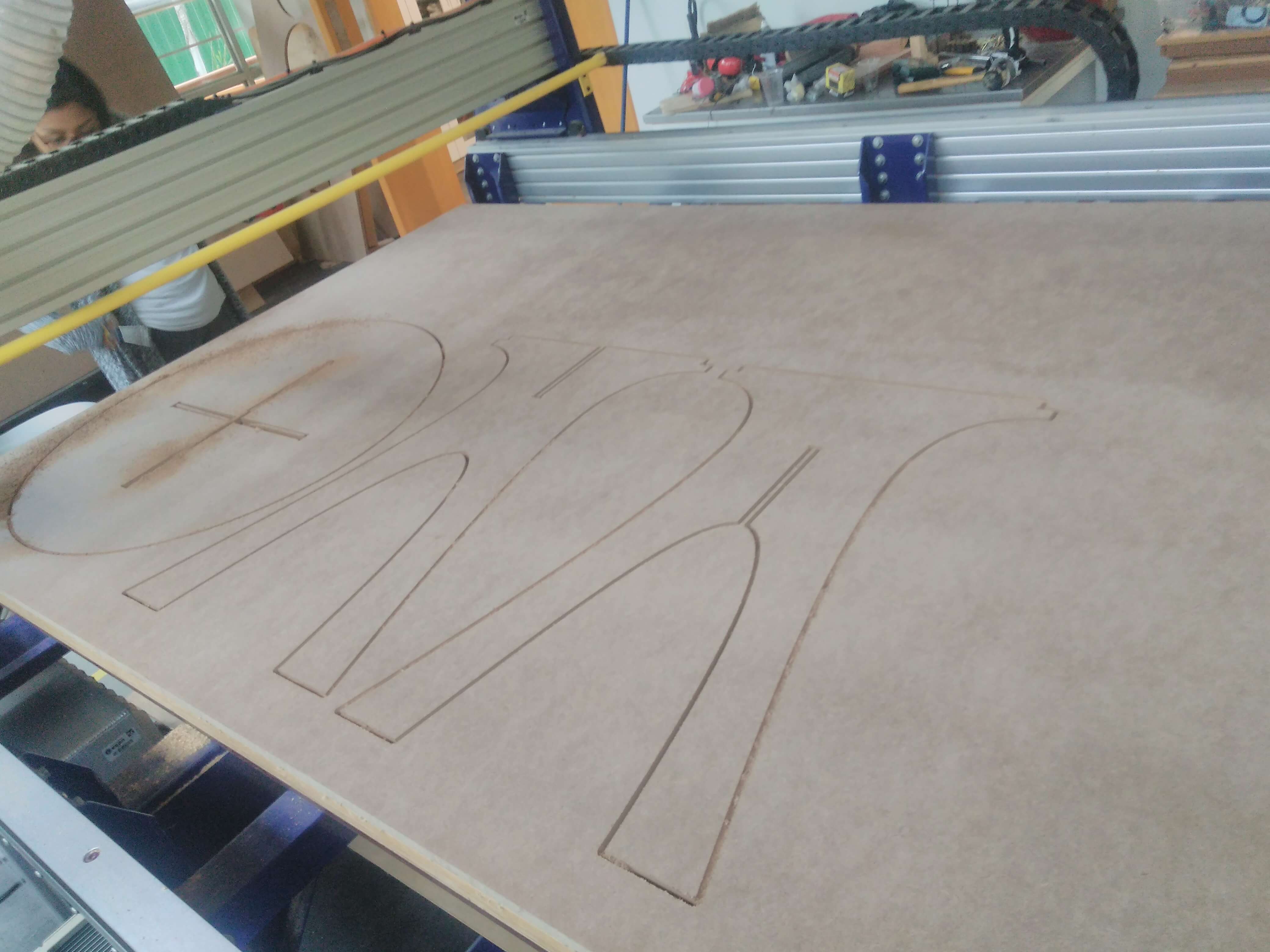
with the correct calibration we send our basic design. Firstly, we imported our .dxf file with Vcarve program which add tabs to assure that the piece out in the cutting process. Additionally, with the program adding semicircles with the program. After these details we must create the toolpath configuration with an specific drill, depth of cutting, and speed. Finally, we exported the file to process in the shopbot. With the shopbot software was launch and set the speed 14000 rpms and load the file, the program warned to press start button and wait a few seconds to start the cutting. So the machine was cutting!!! =)
Test my design
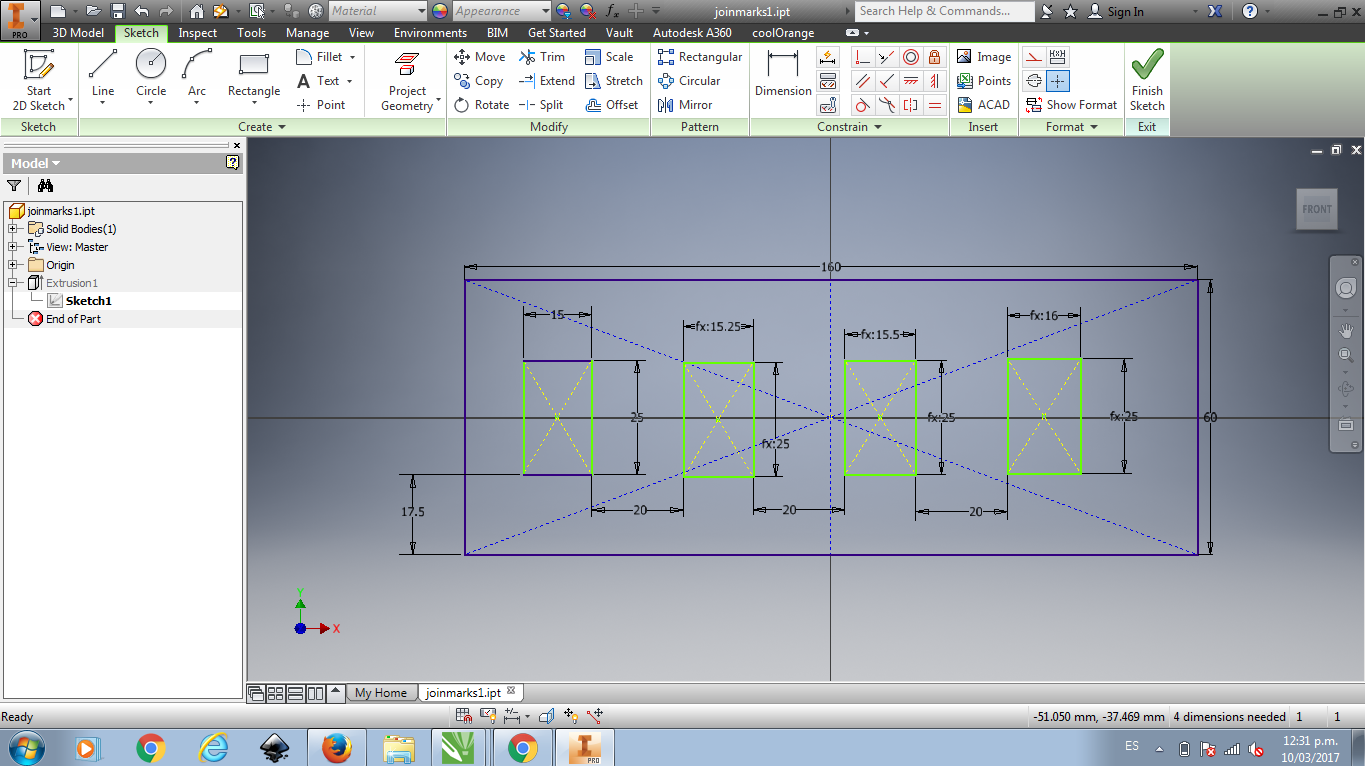
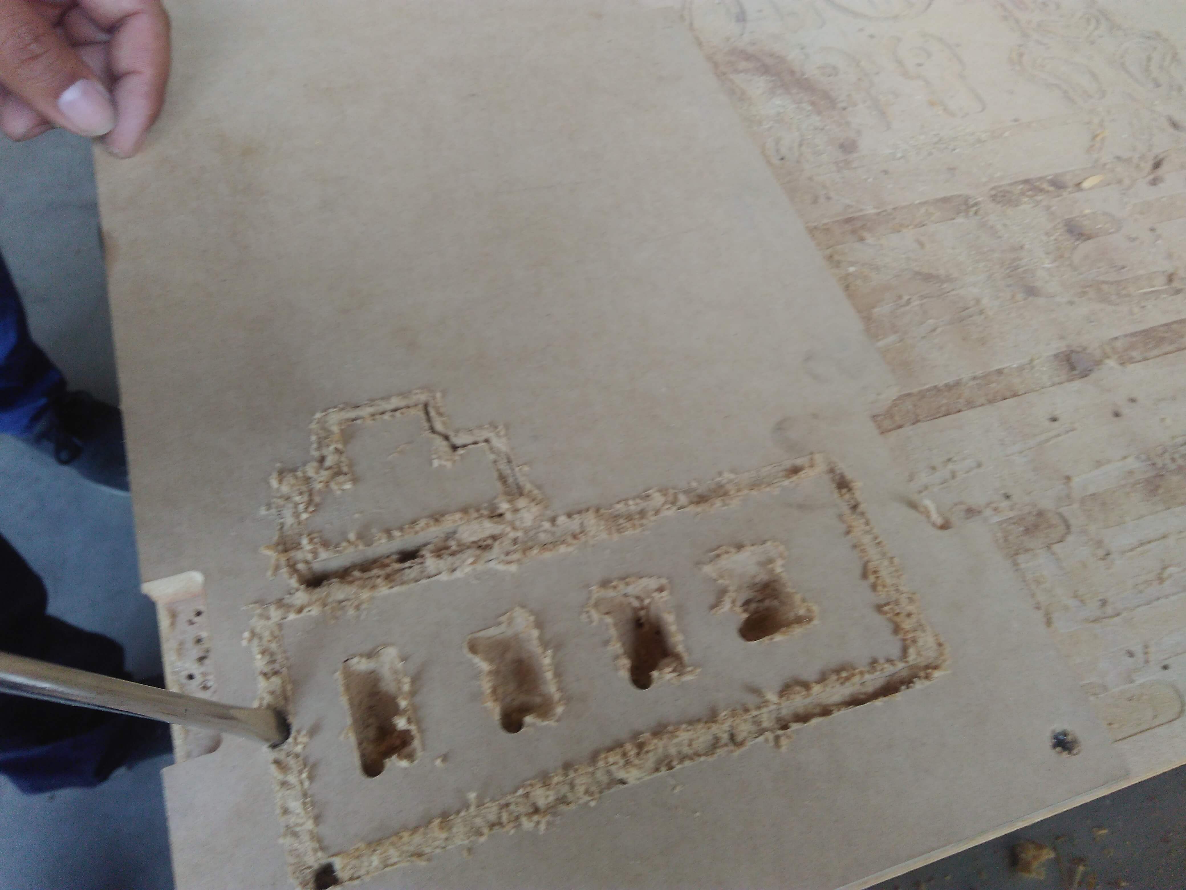
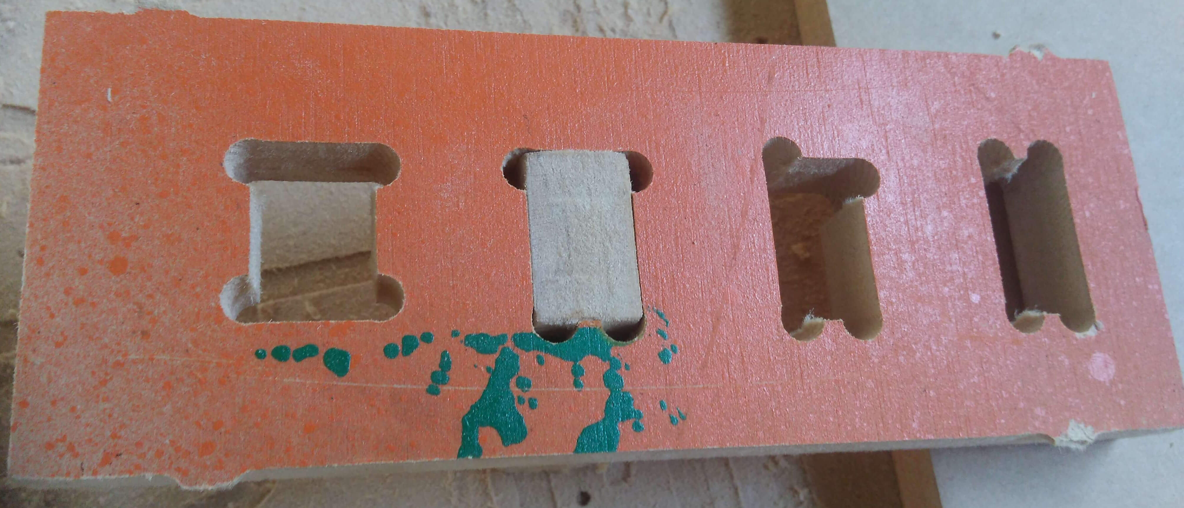
We tested the tolerance with 15 mm depth of MDF. So we designed the T joint with tolerance of 0, 0.2, 0.25, 0.3. After cutting our design we concluded that 0.25 is the best option for 15mm MDF.
The CAD file can download here
Make my design
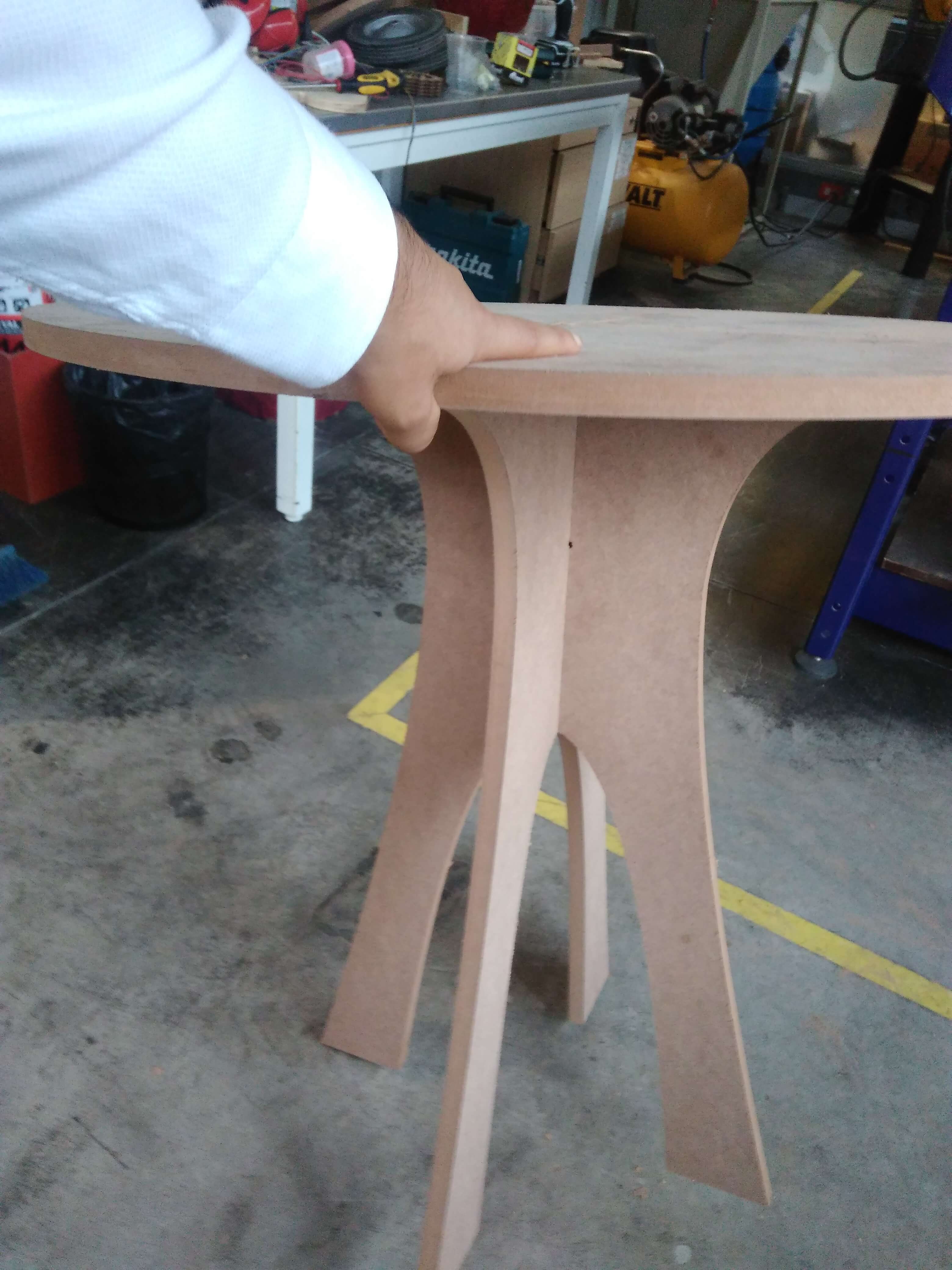
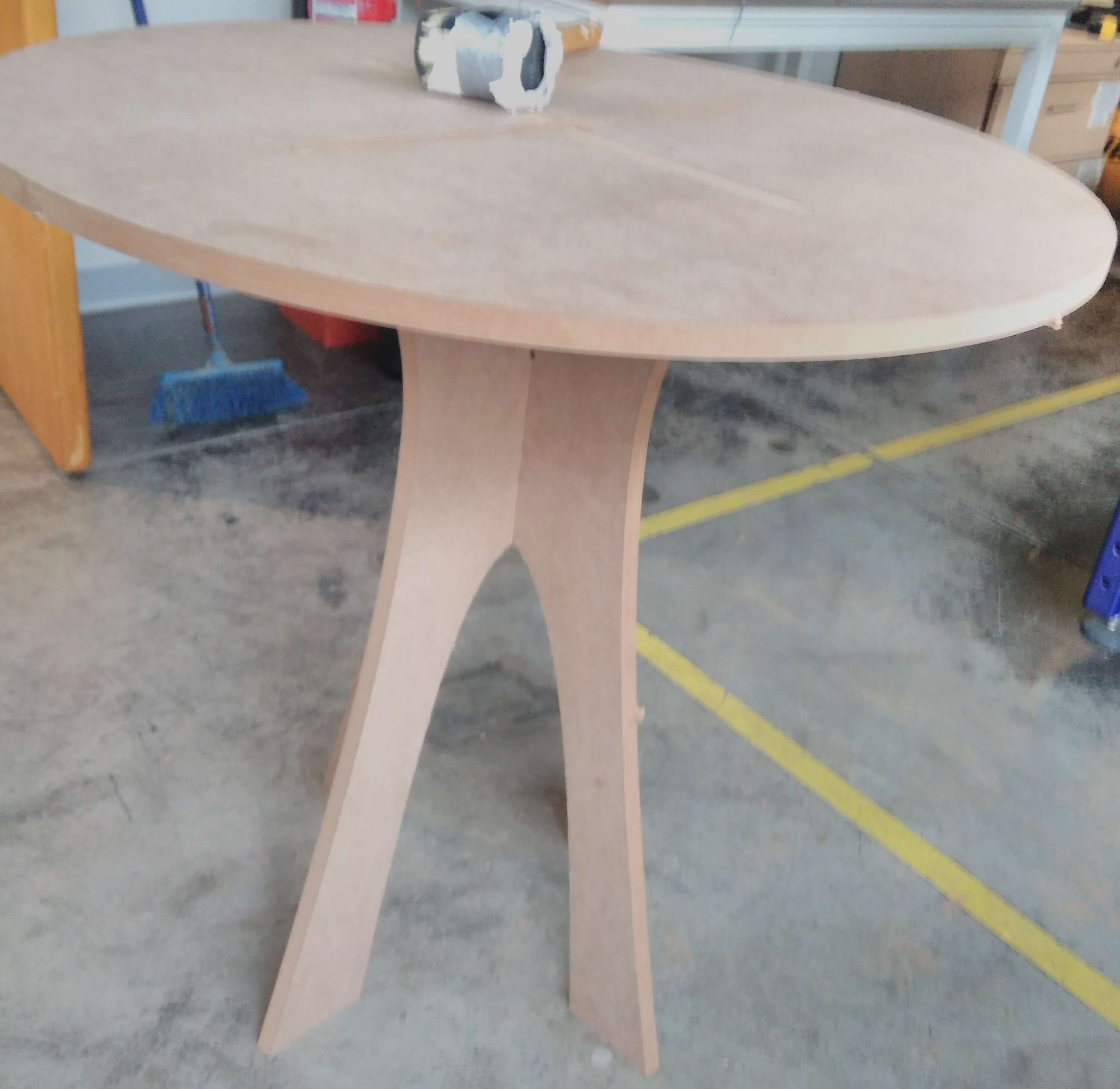
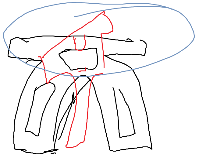
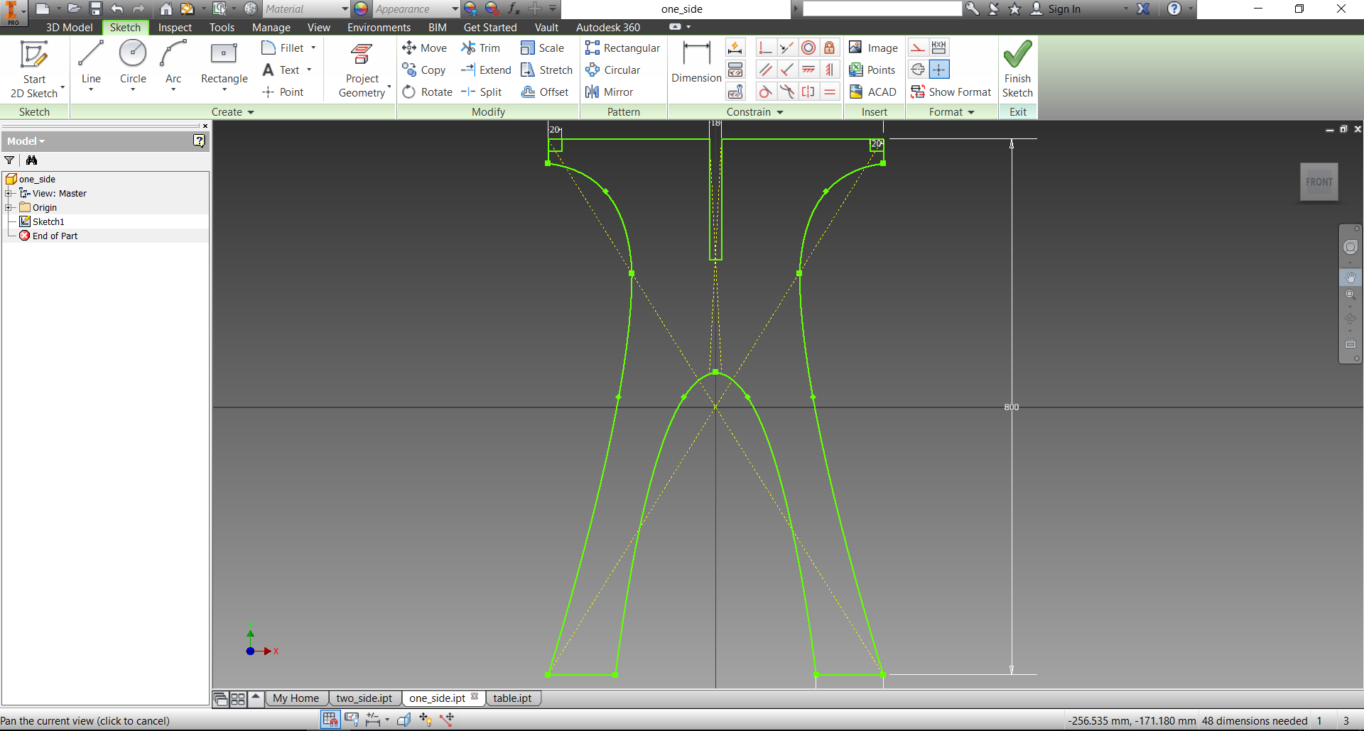
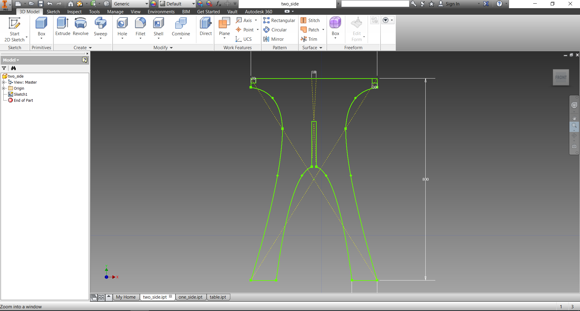
The idea was to create a circle table of three elements. The sketch in the left image belong here shows the idea. The design three elements joint male and female as supports, and the table. The support joins with the table. The project was designed to cut 18 mm MDF.
The CAD file can download here
.
Each step from loading CAD .dwg to cut and assemble parts will describe in the next.
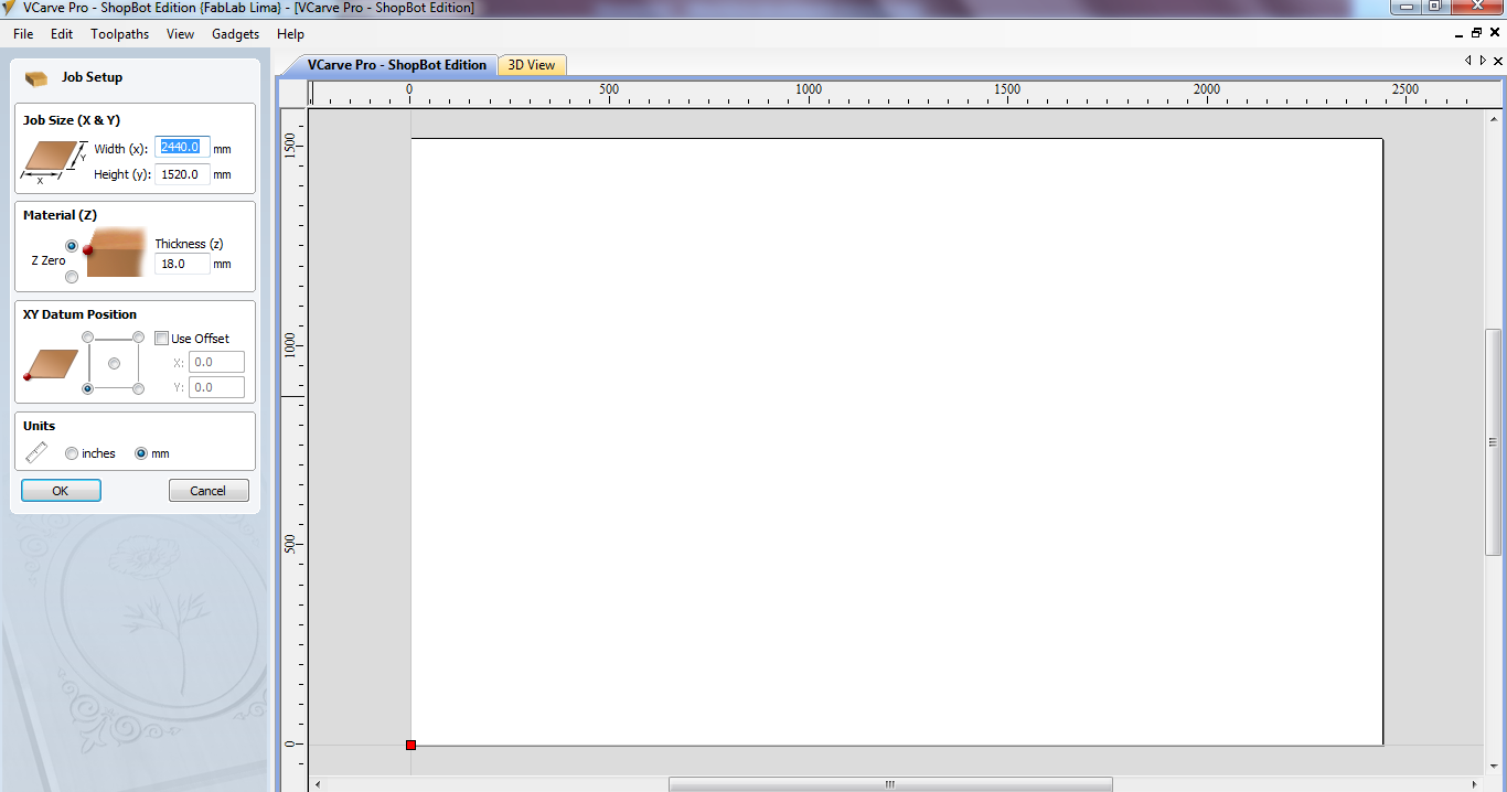
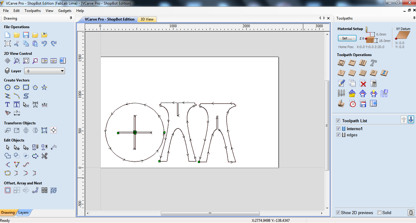
Step 1: Open VCarve program
Step 2: Load .dwg files to current canvas
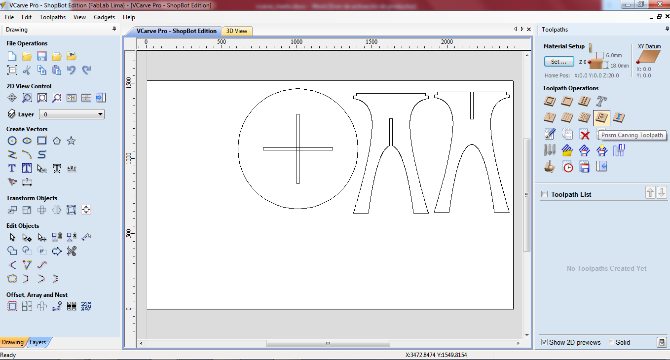
Step 3: Select elements to cut
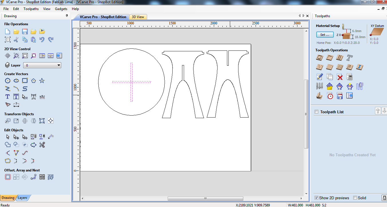
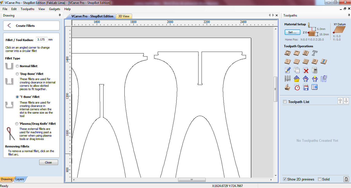
Step 4: Close open shapes and add fillets T-bones in joints.
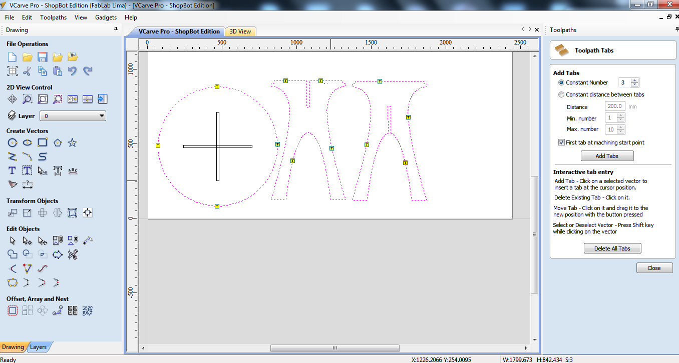
Step 5: Select profile toolpath and add tabs
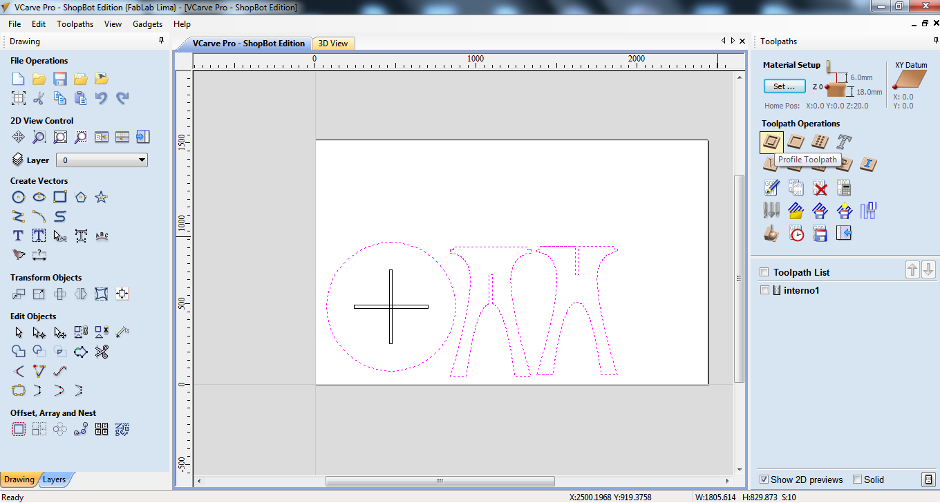
Step 6: Select all exterior edges
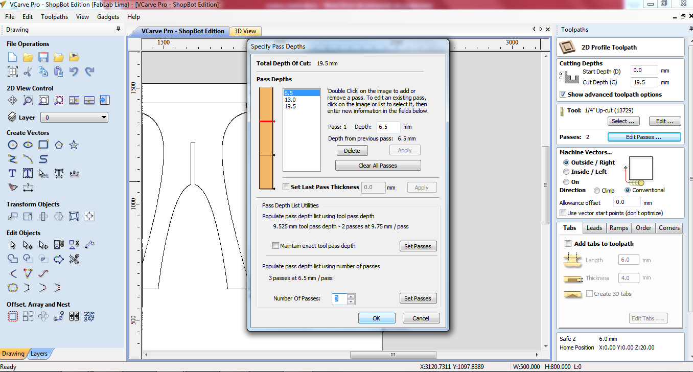
Step 7: Select tool 1/4" up-cut(13729) and passes: 3. According the shape we selected machine vectors as: outside for exterior edges and inside for interior shapes.
Step 8: Press calculate button to compute the trace. Select the profile to export file shopbot.
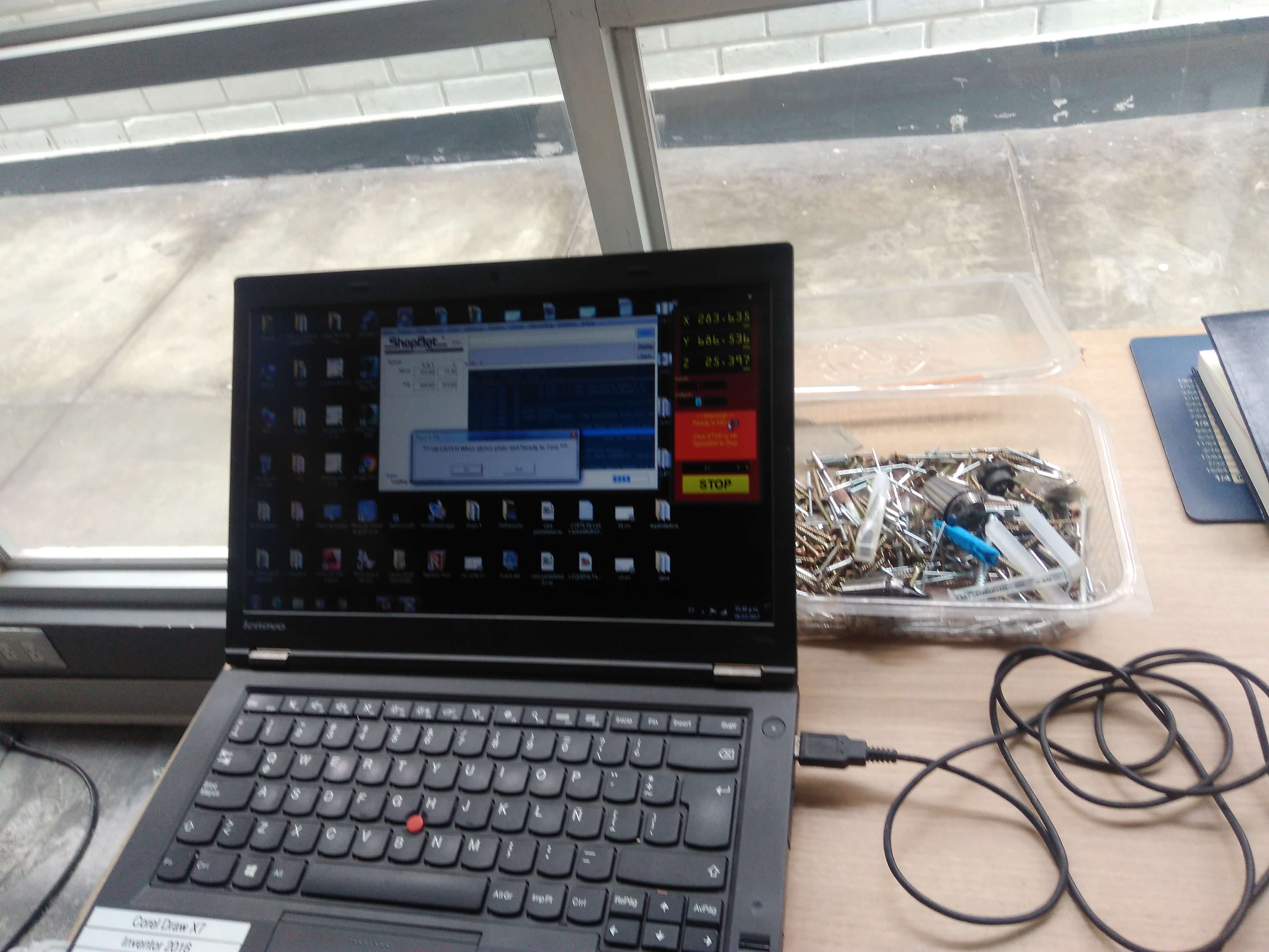
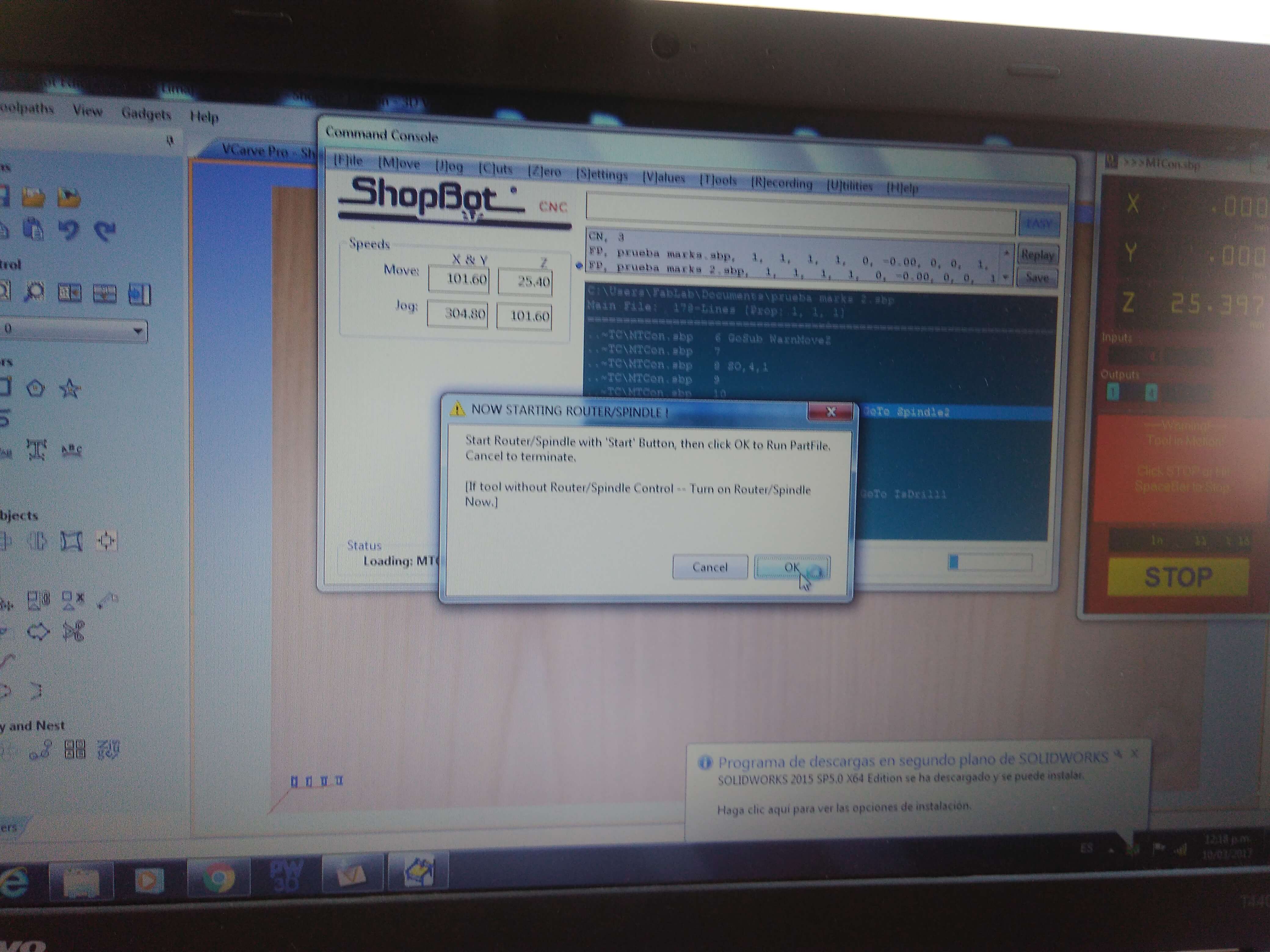
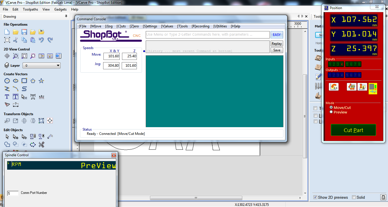
Step 9: Open shopbot program and turn on the CNC machine.
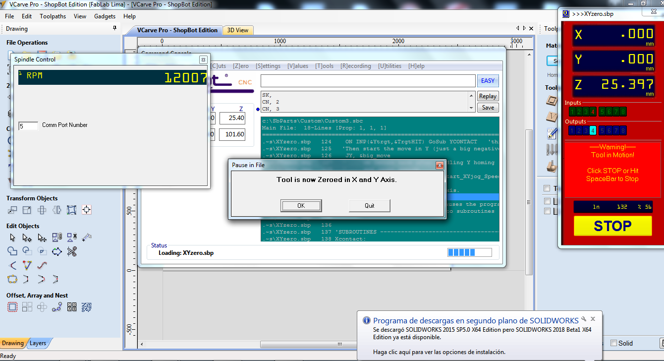
Step 10: Calibrate the machine in axis XY and Z.
Step 11: Load the file sbp of interior, start the button on the machine and finally ok.
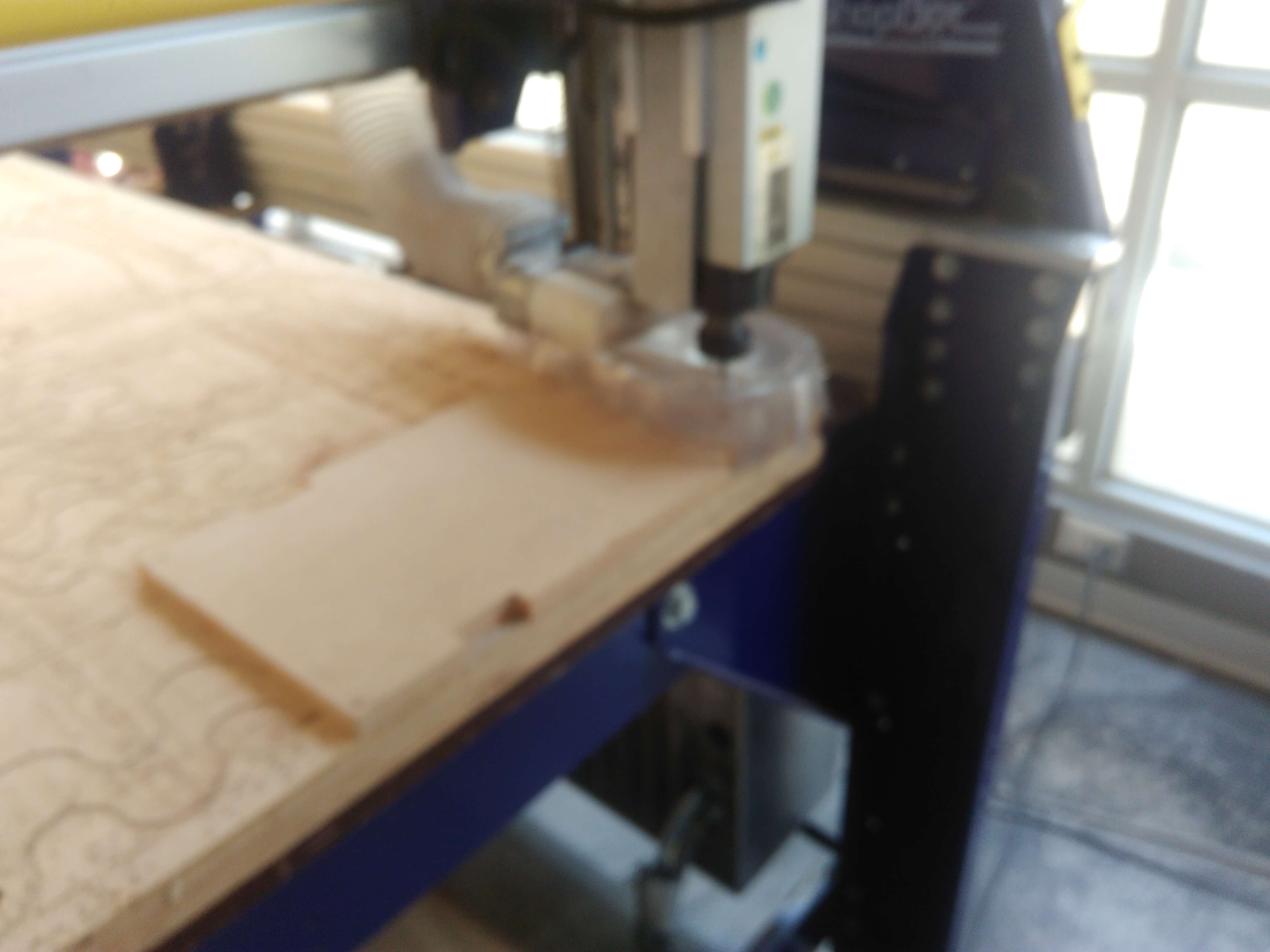
Step 12: Few minutes later, we got .
Step 13: Extract the parts of table.
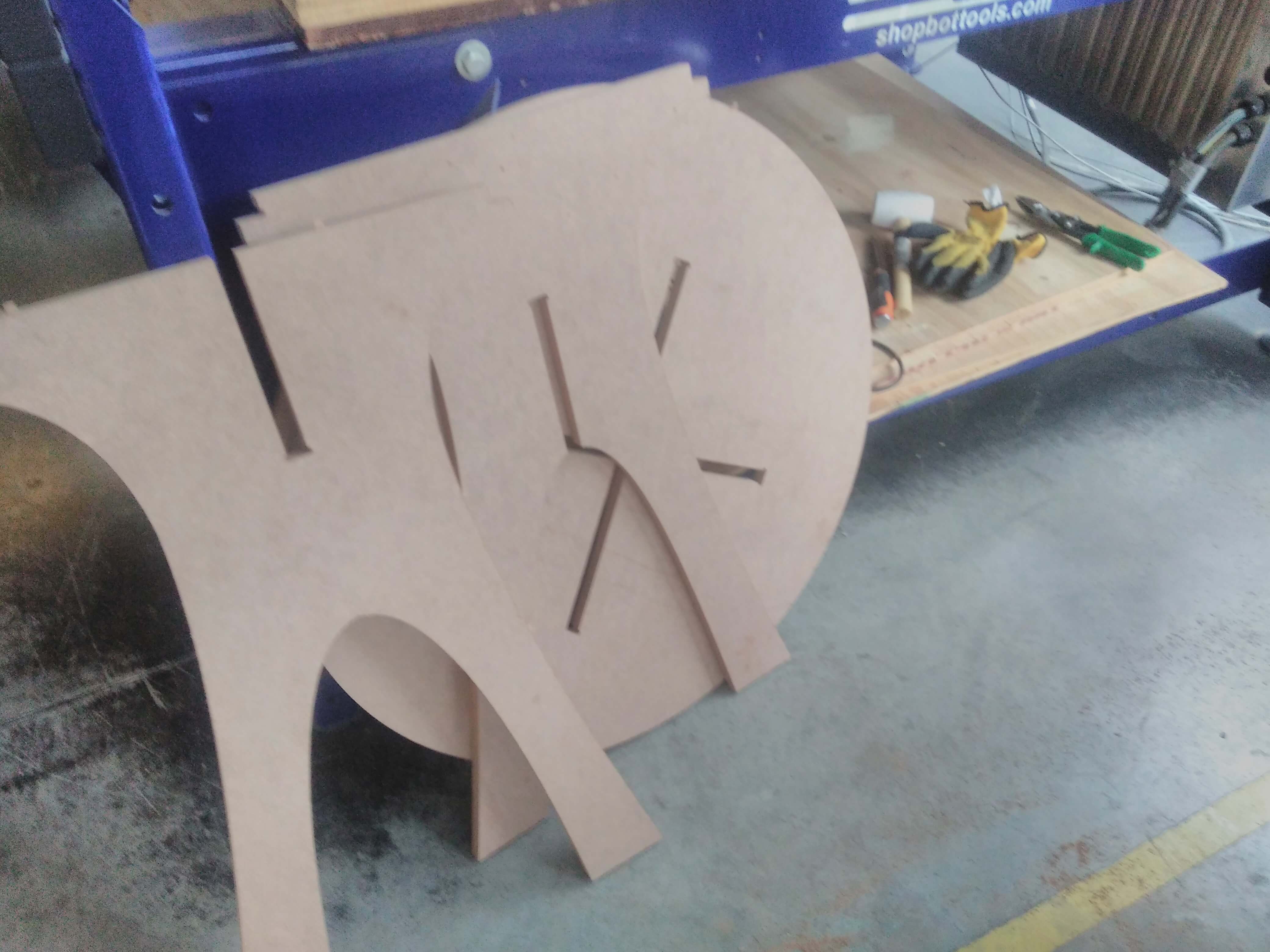
Step 14: After joint the parts, we got.