SMIRROR
RESPONSIVE DEVICE
DESIGN
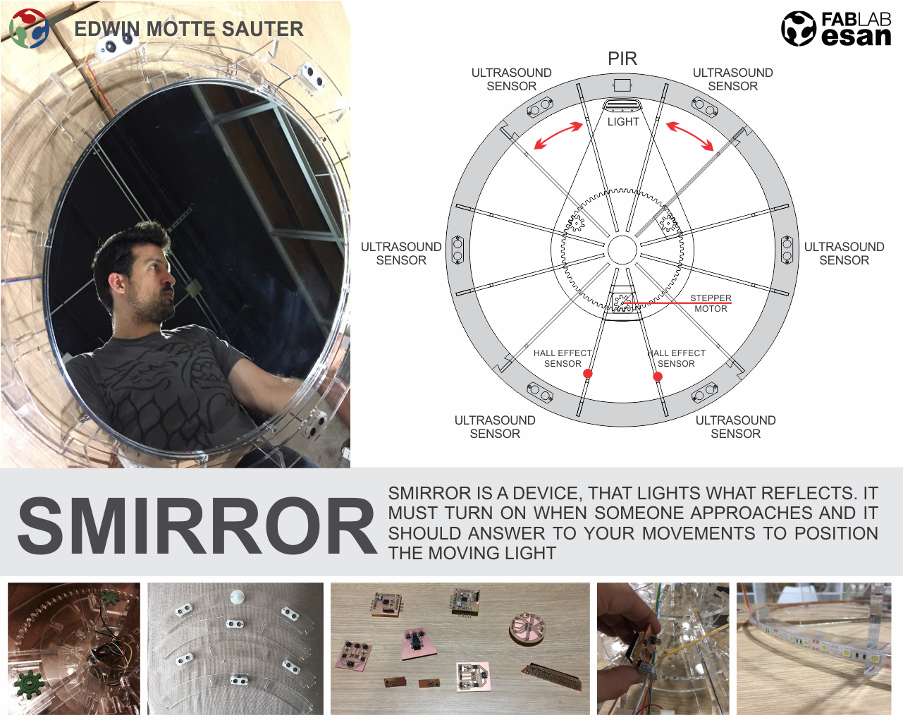
The final project was always an object that follows you and responds to your behavior. Due to the complexity of the initial idea, I changed the perspective, so I came up with a daily object, starting with a need in my own home, a mirror for the bathroom that would respond to my instructions. The mirror should be turned on when perceiving the presence of who needs it and focus its light to where the person points. The first schemes were of a rectangular mirror with lights moving in two directions, horizontal and vertical. However and because of its home application, the mirror should be as simple as possible. For this reason, I changed the shape to a round mirror that only needed one axis to move.
- GEAR FILES
.jpg?crc=4231077443)
.jpg?crc=367522149)
.jpg?crc=3932980579)
.jpg?crc=278416262)
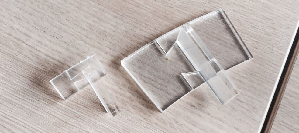
I considered acrylic plastic material to give it a feeling of lightness, almost as if it were only the reflecting surface that was in front of you. In order to do that, I thought of a pressfit type structure, although I did tests for the acrylic, I had problems with tolerance since the plates do not have the same even thickness, there are variations from one plate to another. A 0.05mm tolerance seemd to wok, but not fine.
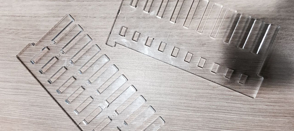

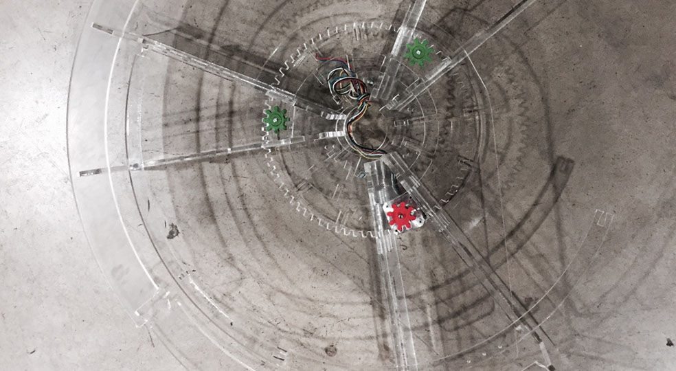
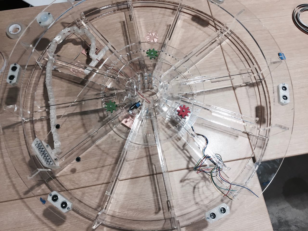
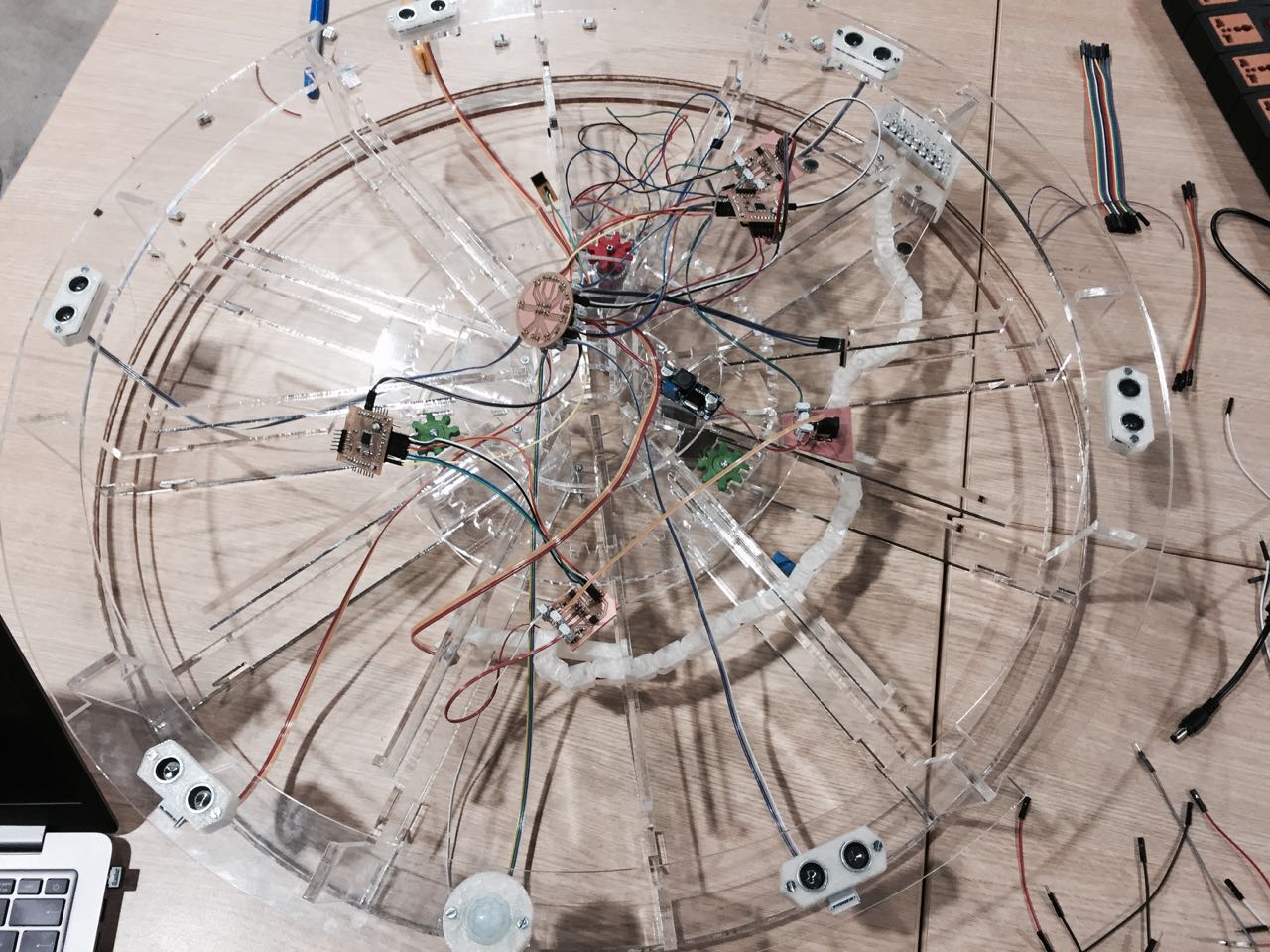
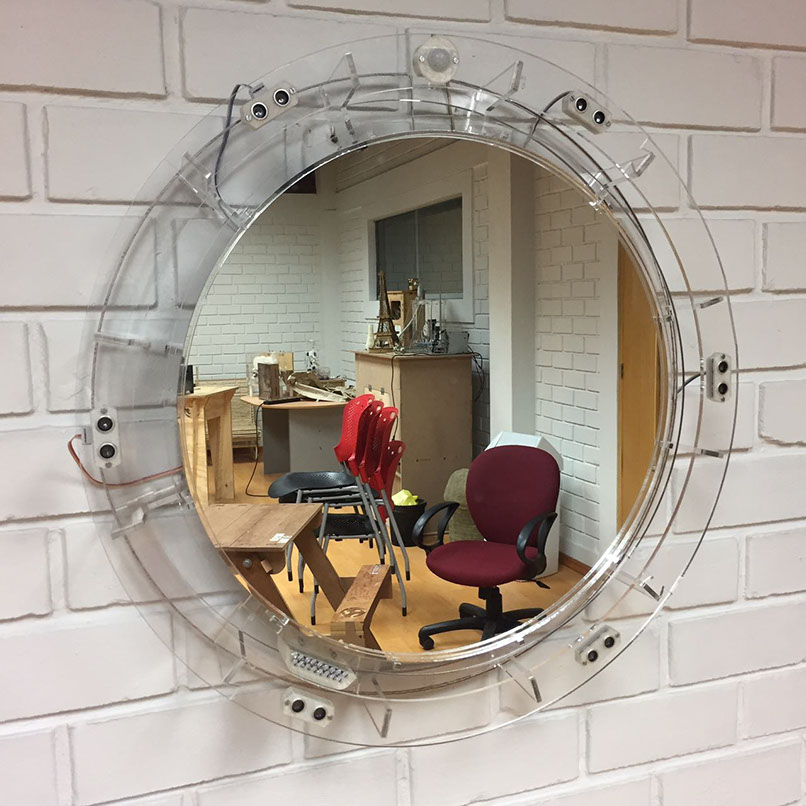
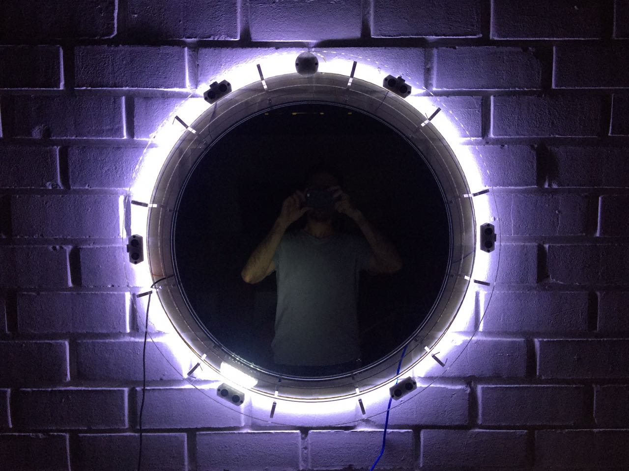
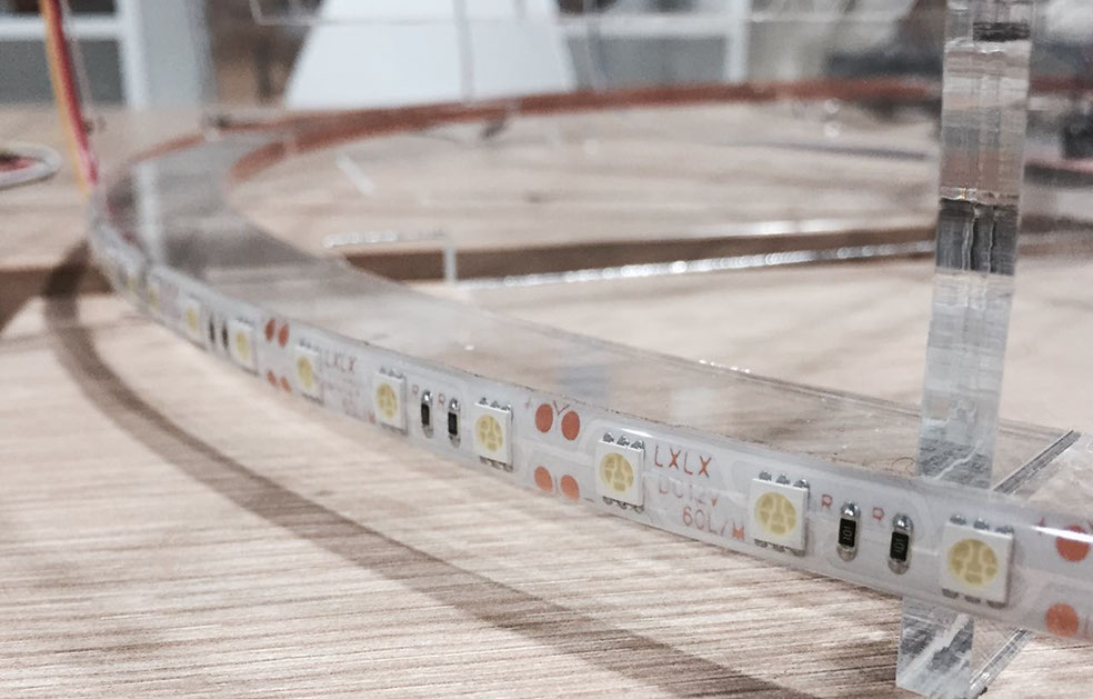
The design scheme consists of an acrylic plastic structure that supports a mechanism that moves thanks to a steppermotor. The motor drives a mechanical arm with internal gear that carries a light to its end. In the back it also has an LED light strip. The acrylic front frame serves to support a series of six ultrasonic sensors and a pir sensor. Finally in the front part there is also another frame that holds the mirror through pressfit unions and prevents it from falling.
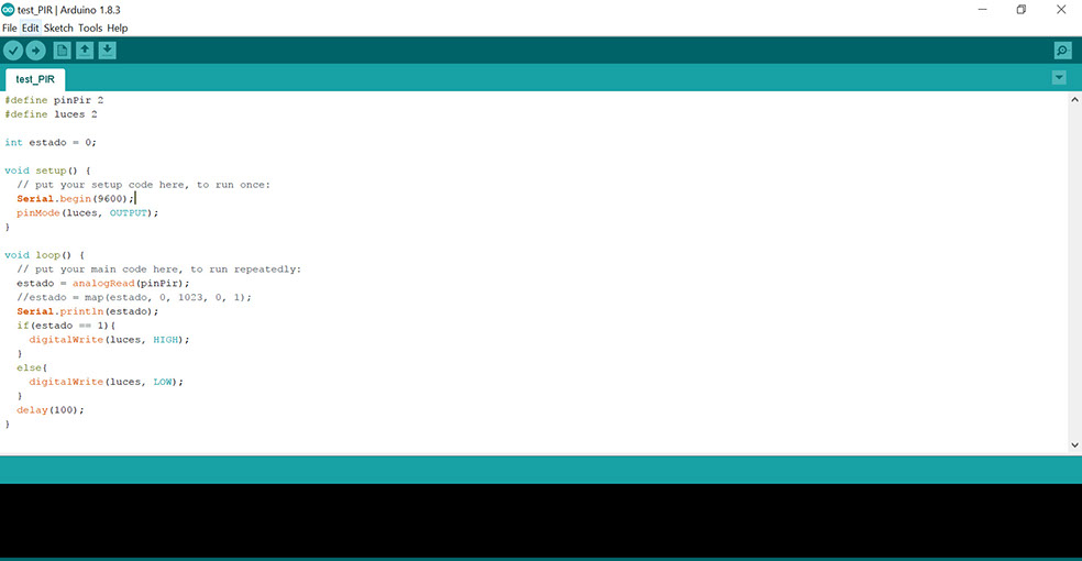
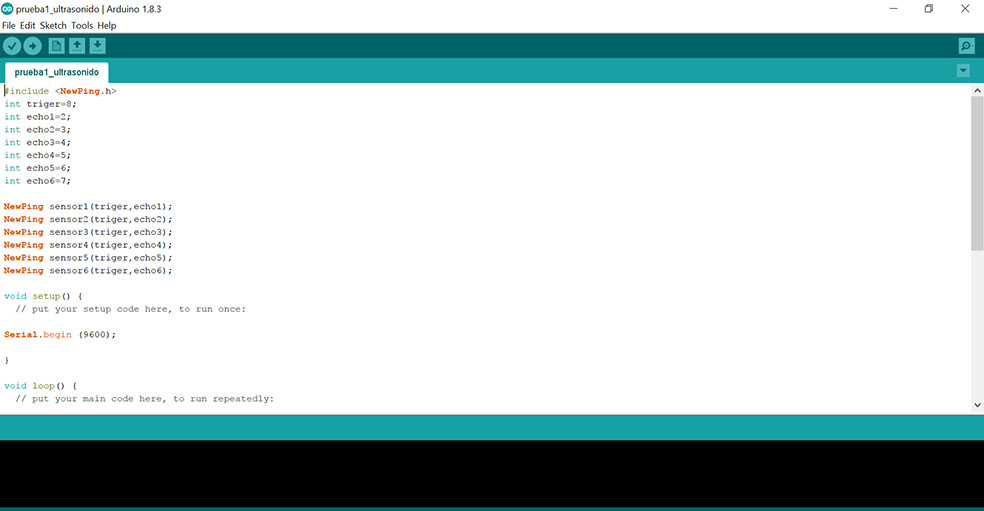
The idea is that the Pir sensor detects the presence of the person and activate the moving light, as well as the LED light ribbon. The ultrasonic sensors are used to activate by proximity or distance (less than 30cm) the mechanical arm to bring the light to that point.
STRUCTURE
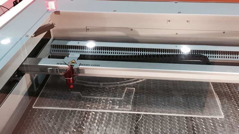
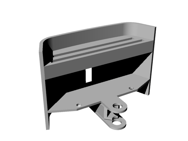
After the joint's tests and the design scheme, I defined the plans in autocad and arranged them for the laser cut.
- 2D AND 3D STRUCTURE FILES
%20122040.jpg?crc=30275232)
%20122100.jpg?crc=239789048)
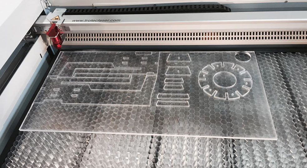
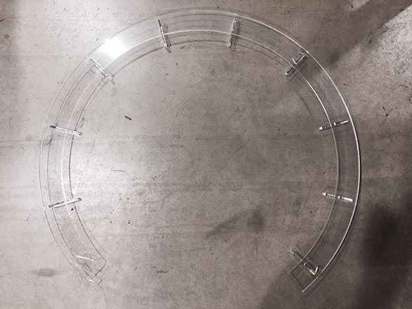
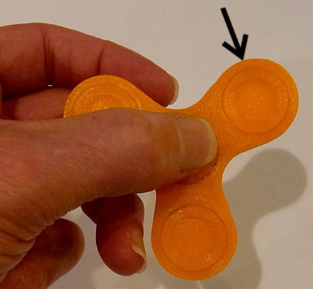
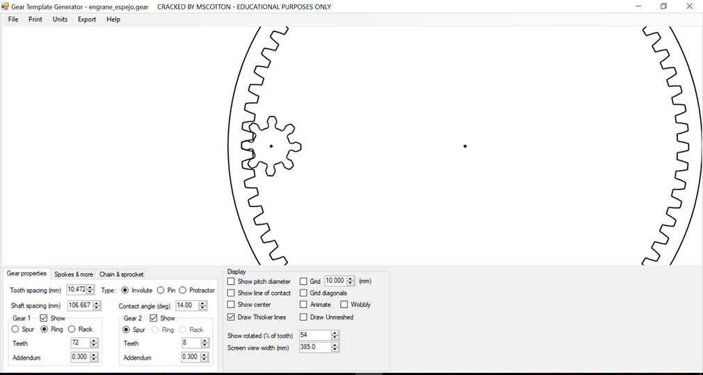
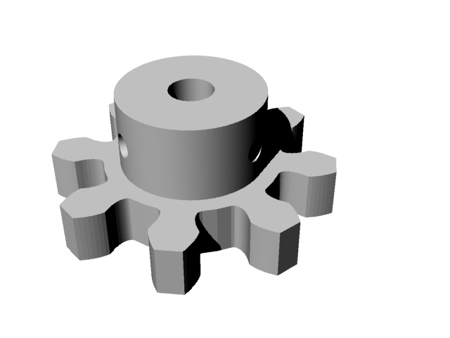
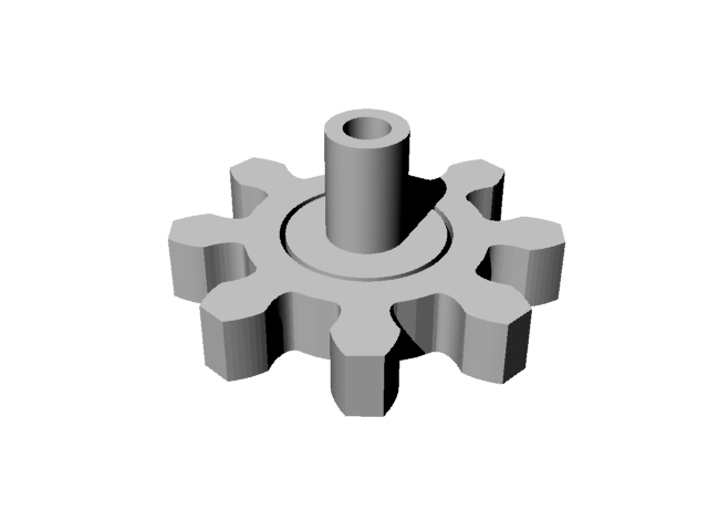
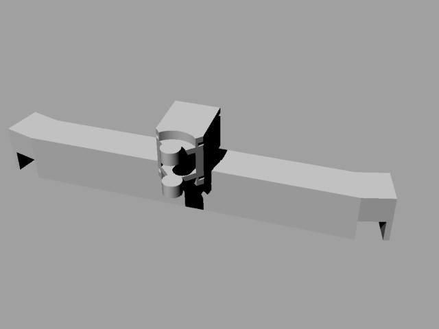
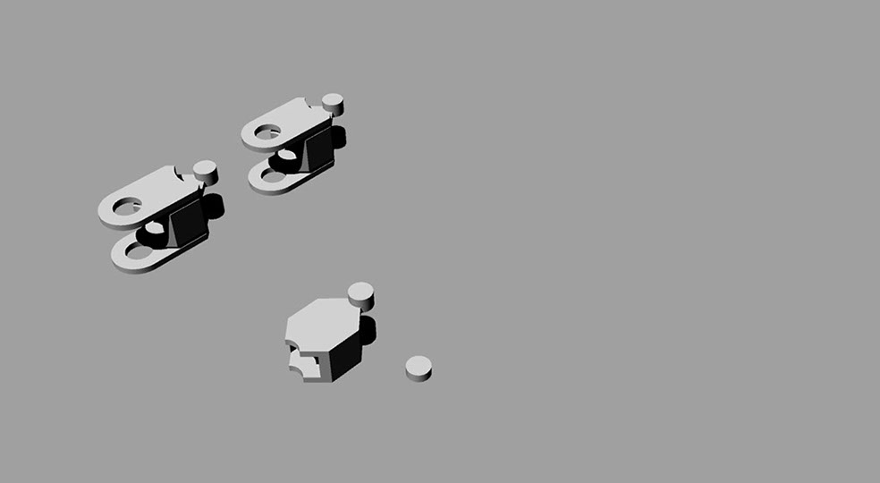
In order to be able to assemble the structure, I must have had the gears. For this I designed mine taking as a reference some bearings of a 3D printed spinner that I found in Thingiverse and using Gear Generator3 software. The gears, as an involute sistem, the radius of both small and big gears depend on the space they had for proper operation.When the pieces were ready, I proceeded to assemble the structure.
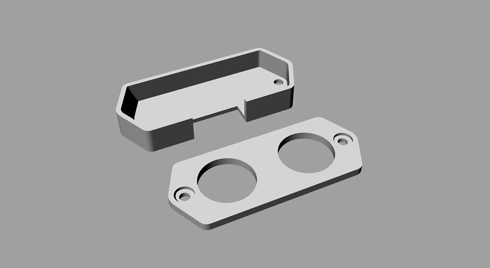
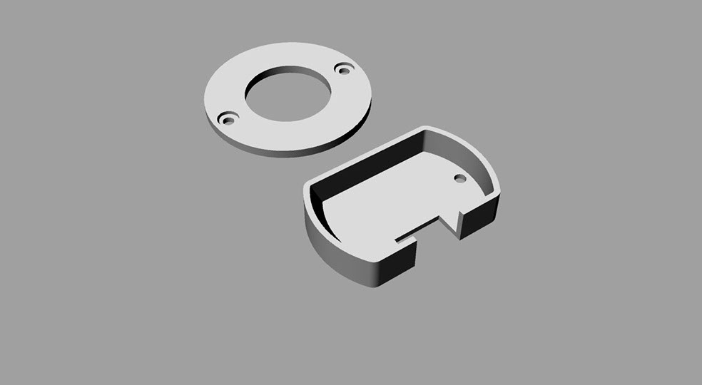
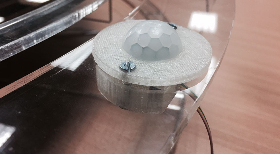
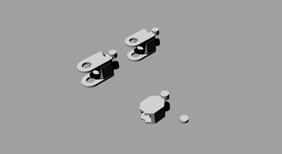
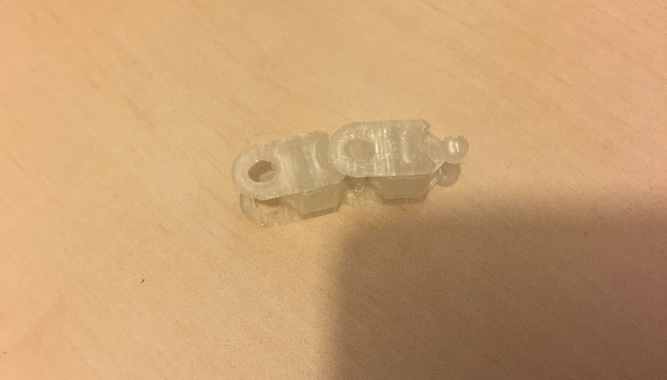
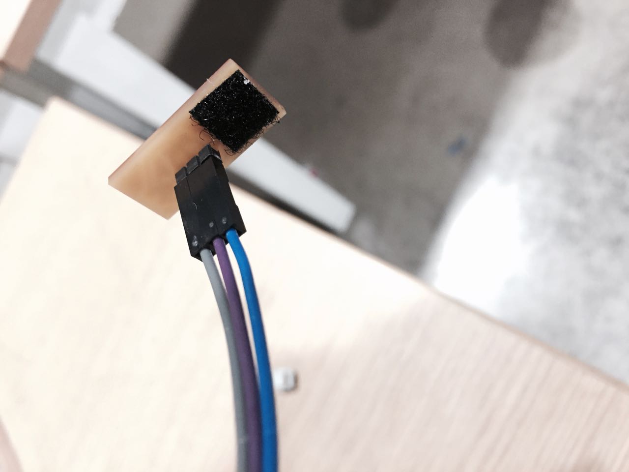
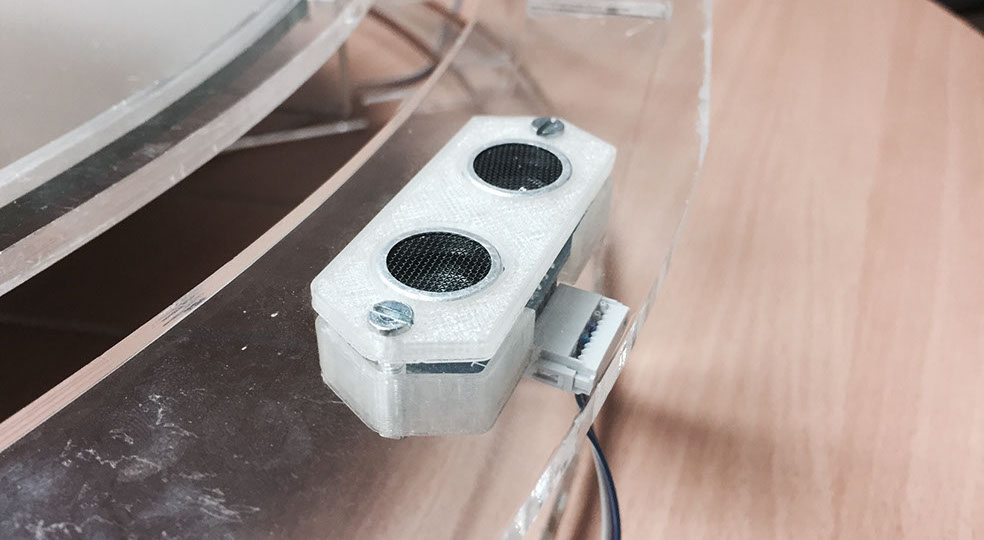
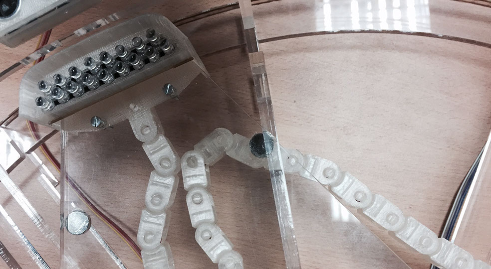
Once the base structure was ready, I started designing the accessories in Rhinoceros, and then printing them in 3D. Couplings were designed between the acrylic and the sensor, for the ultrasonic sensors and for the Pir sensor. The accessory for the LED lights of the mechanical arm was also designed and a modular chain fixed to the structure that protected the cable that power the LEDs. The chain was redesigned from a Thingiverse model and adapted to the use of the mirror.


ELECTRONICS
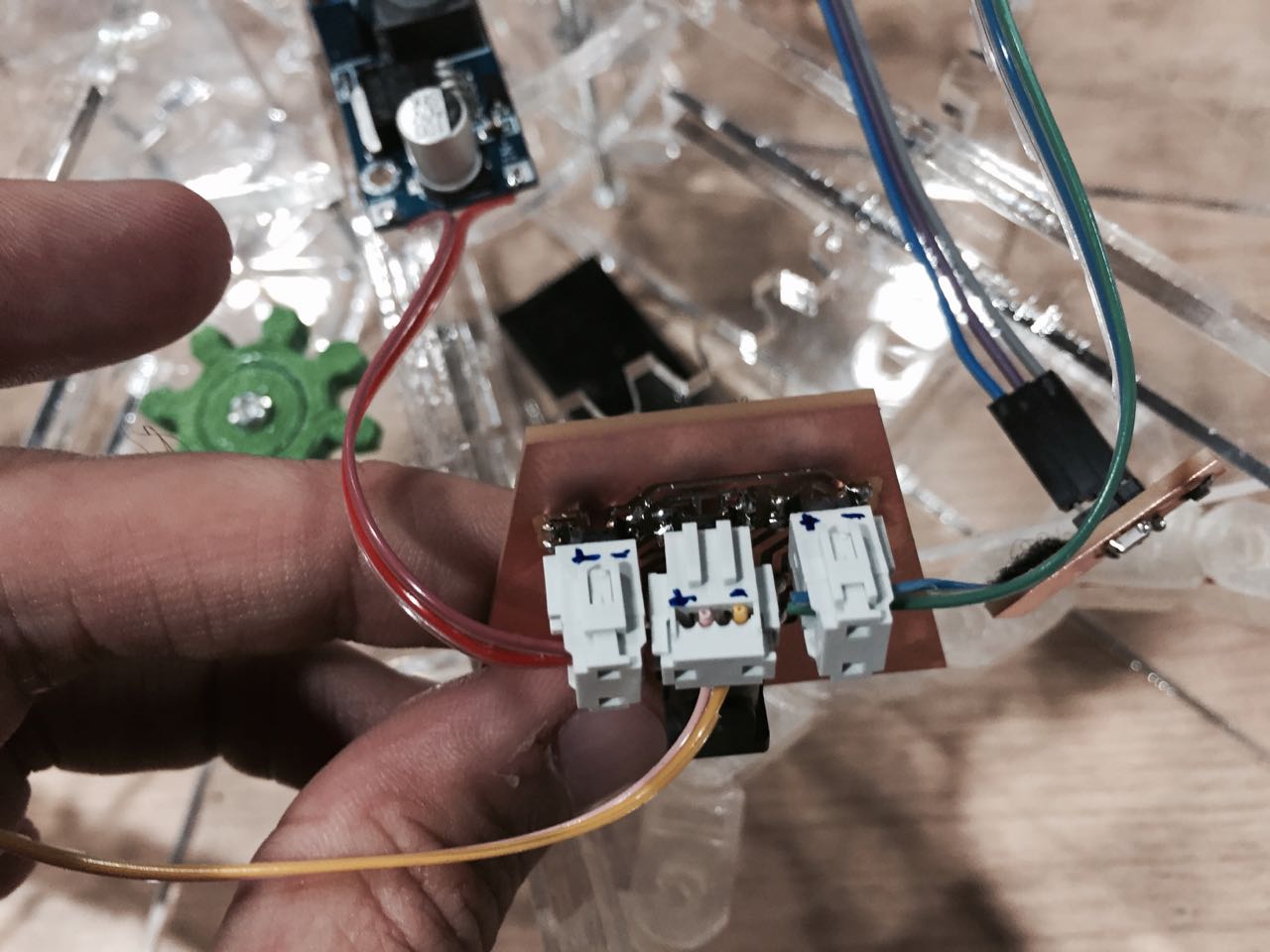
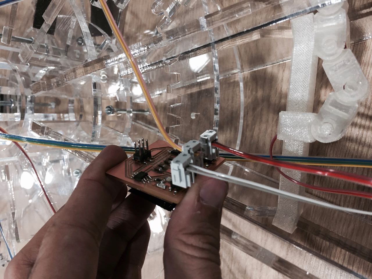
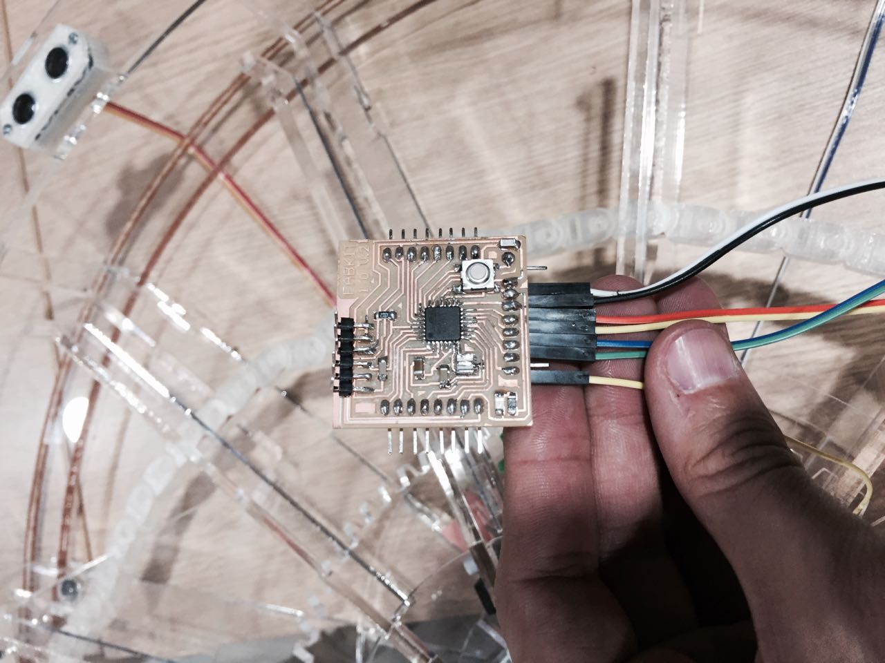
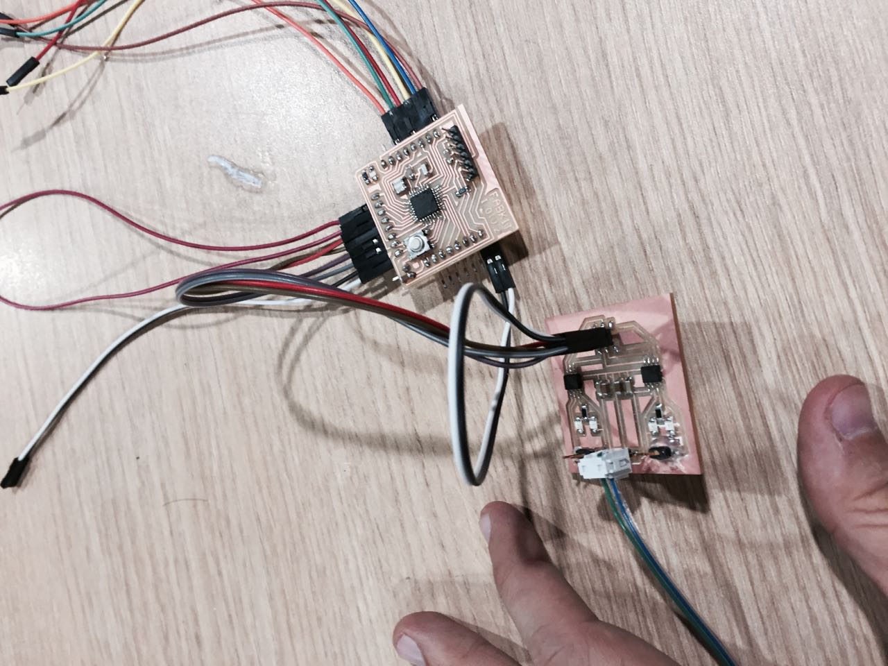
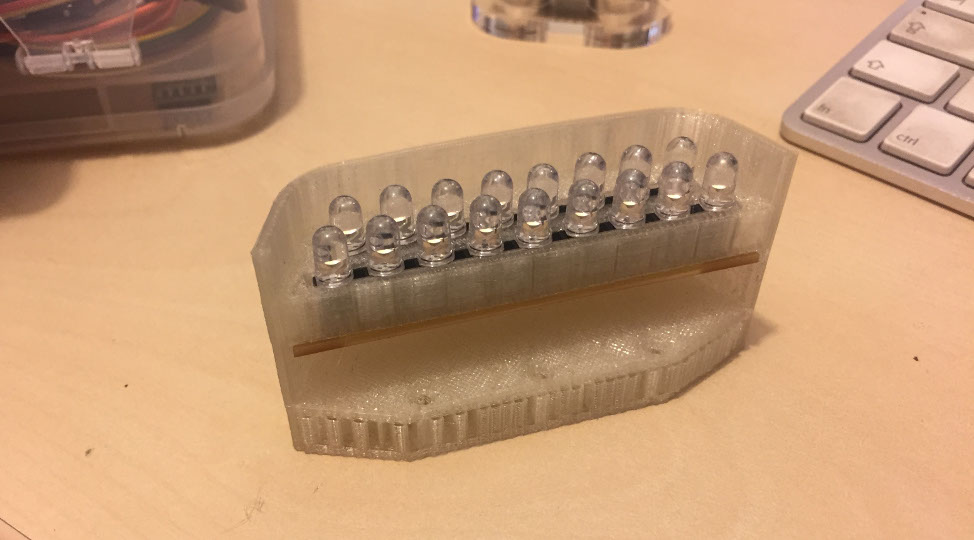
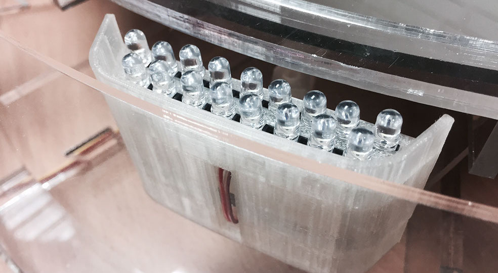
When the structure was assembled, electronic circuits had to be designed. The main idea was to control everything through two fabduinos, but I decided to reduce the number of sensors to work with only one. A power board was designed to power the true hole LEDs and in case one burns out, it can be replaced. Another board was also designed that distributed 5v power to the ultrasound sensor, pir sensor and fabduino. This one was powered by a voltage regulator which in turn was connected to another power board that distributed 12v, for the LED light strip and the LED moving light. For the stepper motor and all the LED I also designed two H bridge board, and to know the 0 position, I designed a hall effect board.
- PCB FILES
.jpg?crc=3999596989)
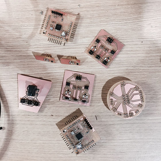
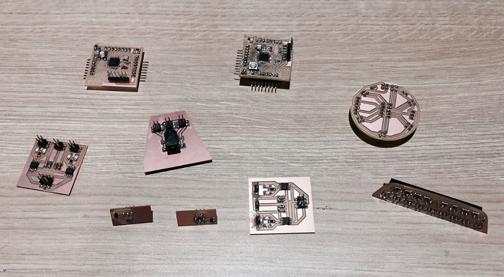
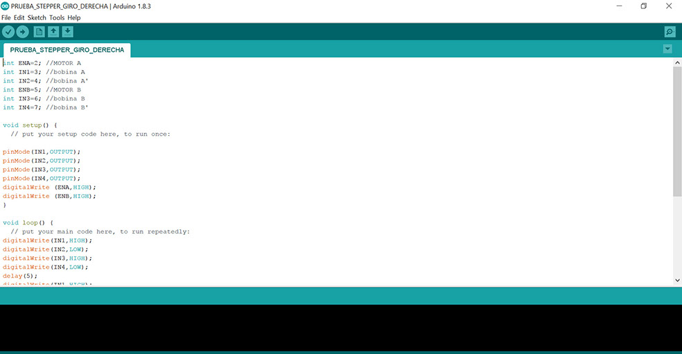
Before assembling all the electronics, it was prudent to test the components separately, so I tested the sensors one by one, the stepper motor and the lights, I even set the regulator output in 5v.
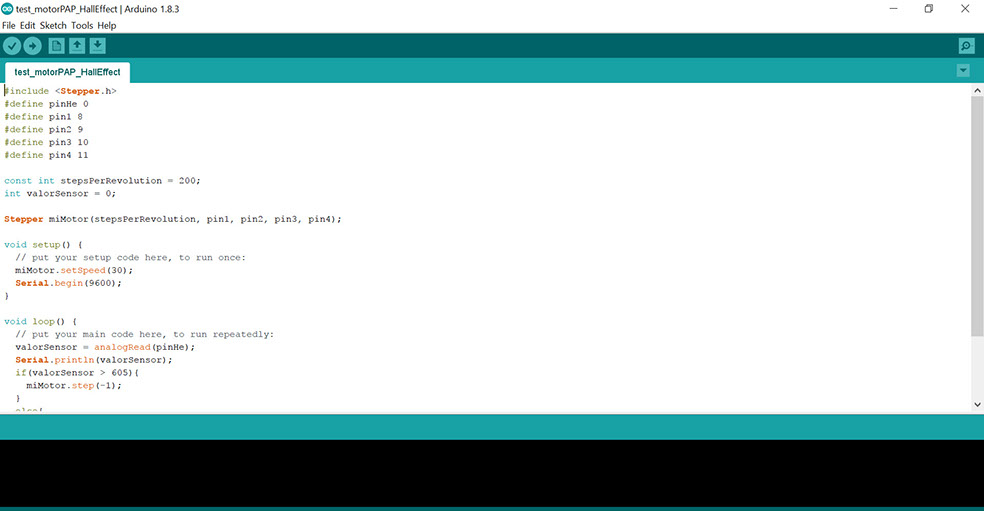
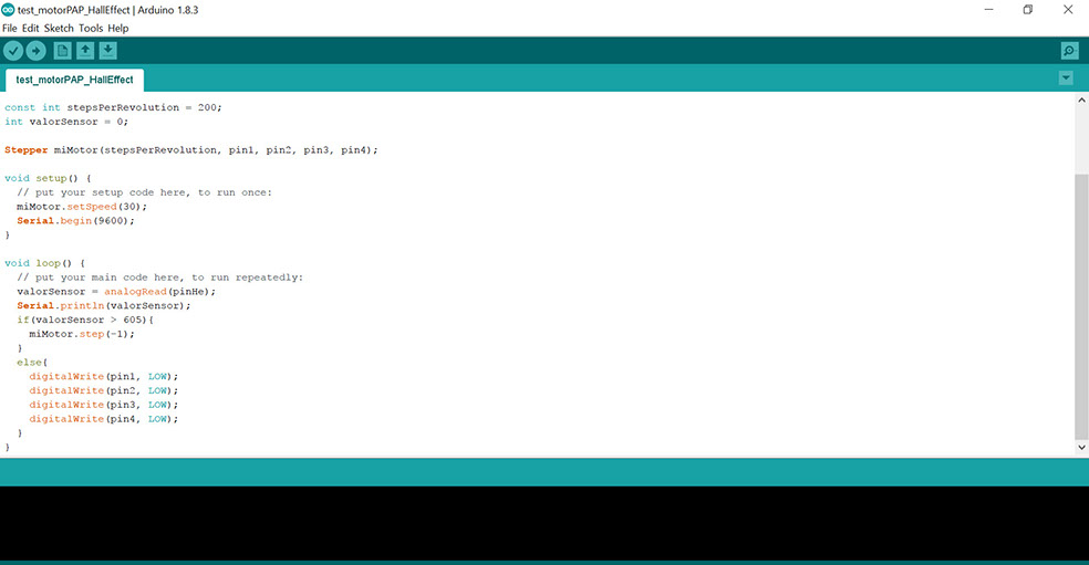
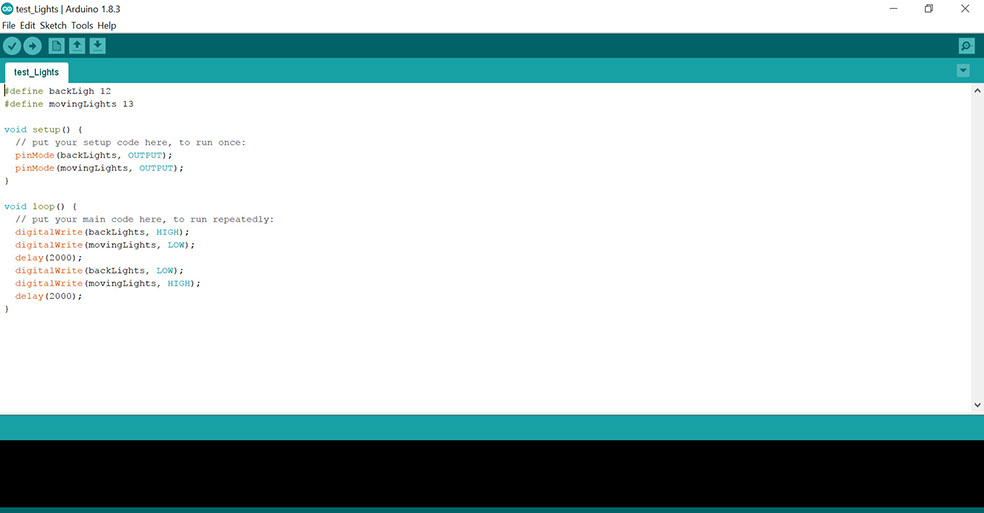


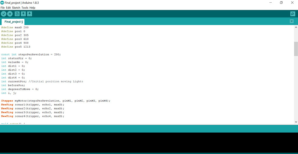
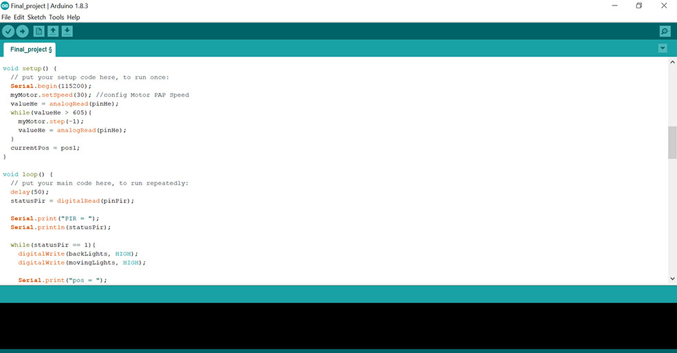
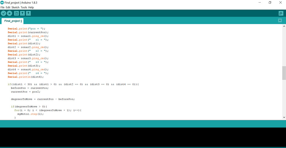
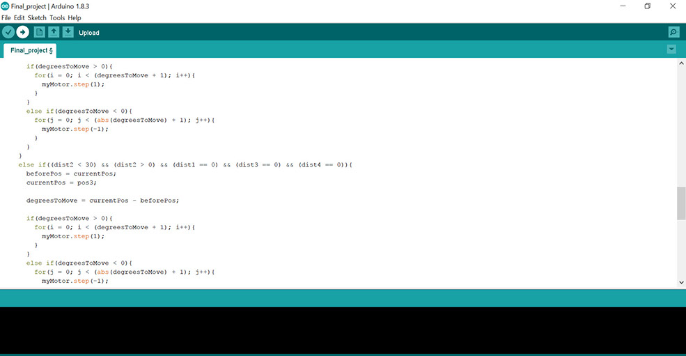
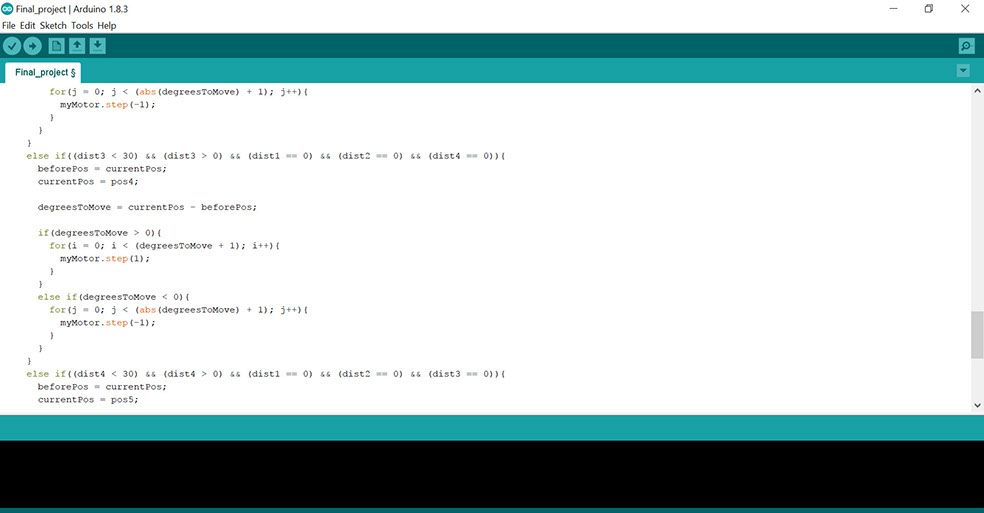
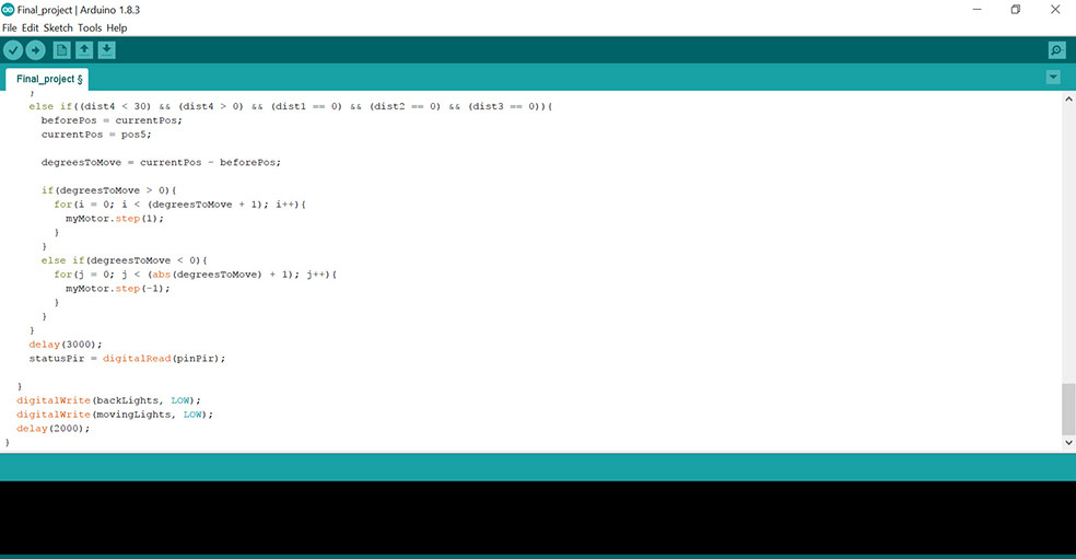
PROGRAMMING
The final code was quite difficult, even the project did not work the day of the presentation because of a calibration problem associated with an error in the code. To move from one position to another, the stepper motor had to move 305 steps, the difficulty was in defining how to return to an earlier position. It had to be taken into account that the arm with the LED could only come and go, but not take a full turn. To solve it I had to establish two positions, one of beginning and one of end, associated with the location of each stop.
- PROGRAM FILES

BOM
Here at ESAB's FABLAB, we had most of the materials and components used in the project, such as acrylic sheets as well as electronic components. However, there are some modules and materials that should have been purchased, such as the voltage regulator, the 12v / 5amp source, the 17 white LED truhole (in the laboratory there was not the amount I needed) and resistors of 270 and 470 ohm.
xmottex@gmail.com


