COMPUTER-CONTROLLED CUTTING
WEEK 3
- Make lasercutter test part(s), varying cutting settings and slot dimensions (group)
- Cut something on the vinylcutter (individual)
- Design, make, and document a parametric press-fit construction kit, accounting for the lasercutter kerf, which can be assembled in multiple ways (individual)
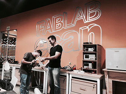
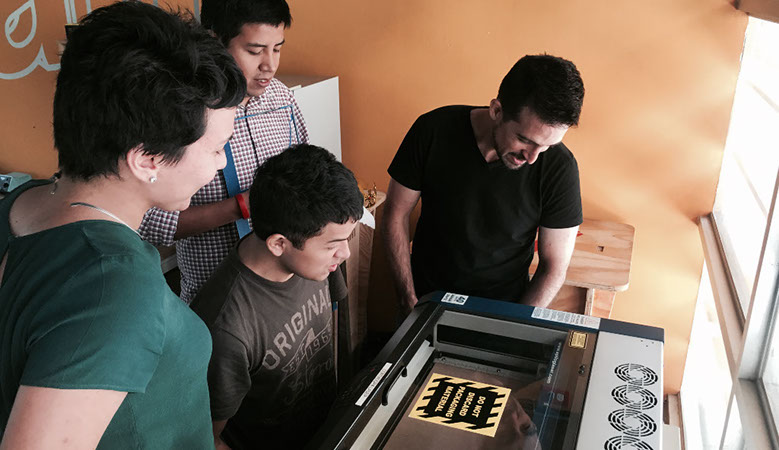
LASERCUTTER TESTS
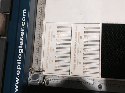
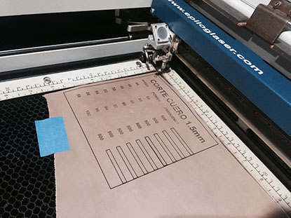
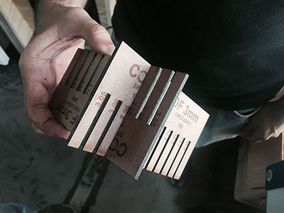
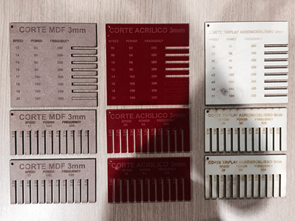
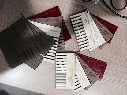
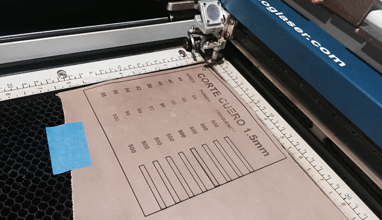
This was our first group assignment, we decided to produce a catalog of "cut (speed and power) and thickness" for various materials found in the FABLAB. The catalog would serv us for our individual assignment. The first thing we did was to locate materials in the LAB and do a little mesure and research on them, so we could establish some initial parameters. The chosen materials were: wood (3mm), acrylic (3mm), mdf (3mm), leather (1.5mm) and mica (0.6mm). Before cutting we designed the format to show the results of the test, the program was Corel Draw.
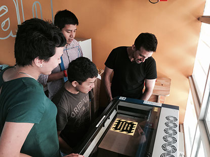
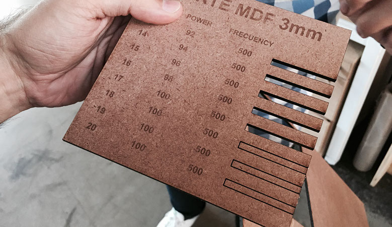
Then we set the cutoff parameters for each value to be tested, the Raster and Vector settings, were the most important, due to the gradation of speed and power. Raster defines the engraving in the piece, which can be from simple text, to photographs and graphics. Vector instead defines the cutting path in the material.
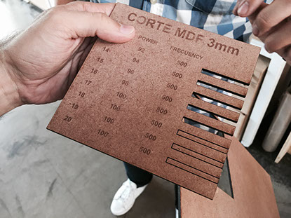
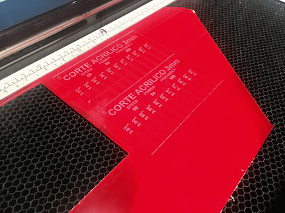
We did the same procedure for each material, we tested first Raster and Vector Parameters and then the thickness for the press-fit assignment. We had to take into account that the more speed, the less time, but the possibility remained that the material had not been cut properly. With the power we could define the intensity of the laser, however we ran the risk of burning the material. In addition, depending on the type of material and its thickness, the values of power and speed were very different.
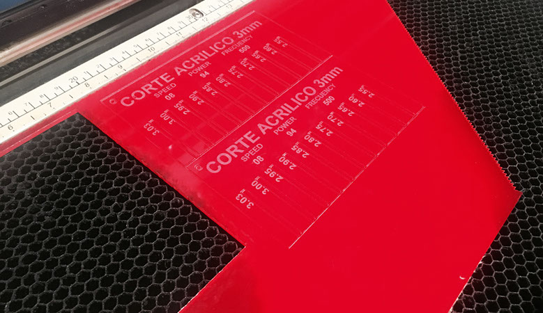
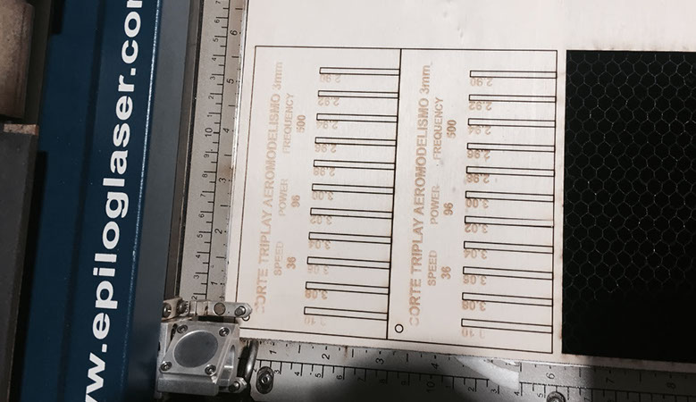
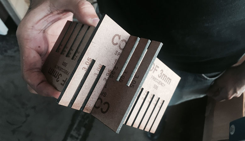
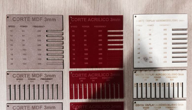
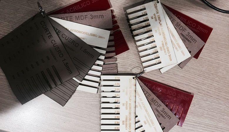
The final idea was to have a catalog for the FAB-LAB, and future assignments, to leave a record that allows us to define cutting parameters depending on the work to be performed on the epilog laser cutter, since these tests only work for this particular machine.
THE VINYLCUTTER
For the vinylcutter the first thing to do was to find and/or prepare a .png black and white image. I find a dragon on the web and and I prepared for the cutter. In the lab they needed a badge for our lockers, so it was perfect for the occasion.
To open te cutting program, I must acces to it through a linux platform and with the terminal emulator. The next step is to load the image and set the path (we clic an icon and the program does it by itself -> make path). Then set the force and the velocity and clic on the icon make .camm.
Then after the vinyl is cut, we have to remove carefully everything we do not need from the image and we have to put the transfer sheet, which is a sheet that serves to fix the part without glue, to be able to place the vinyl on the desired surface, without moving the pieces that are separated.
Finally we stick it and we remove the transfer sheet slowly so the tiny pieces don't move.
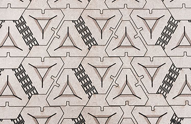
PARAMETRIC PRESS-FIT CONSTRUCTION KIT
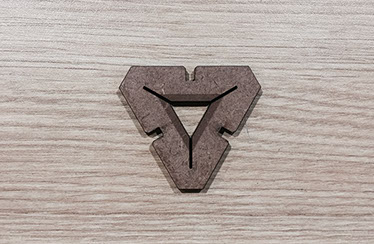
With this assignment my idea was to make a single modular piece for the whole construction kit. First I thought in a simple triangle but I wanted it to be more versatile, not just 30º, 60º and 120º. I also wanted an orthogonal possibility and an even more flexible piece, so I add a kerv articulation.
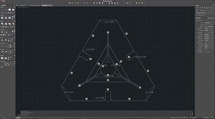
I started drawing the triangle and setting the parameters for the piece in FREECAD. This program has a different drawing logic than Autodesks AutoCAD.The parametric solution did not work as I expected, every time I altered the size of the joint, the overall shape of the piece changed.
FREECAD FILES
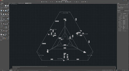
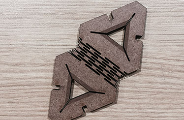
Then I preferred to continue the piece in AutoCAD. The most difficult was to design the articulation, the first one was an unsuccessful attempt, because only with four streaks, the piece broke.
AUTOCAD FILES_01
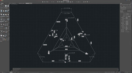
The second piece had one more streak, five in total. I didn't want to add much detail until piece work properly.
AUTOCAD FILES_02
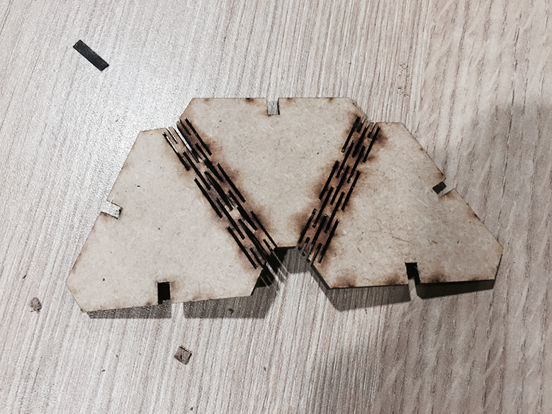
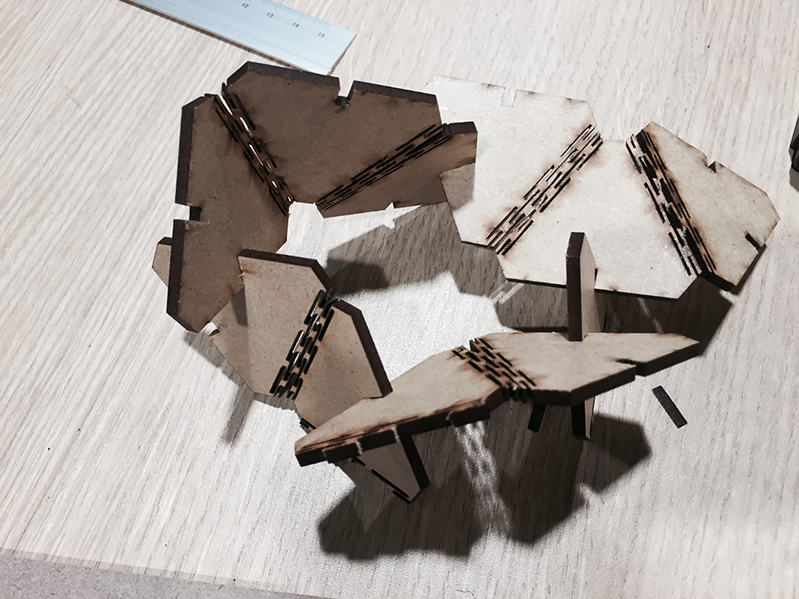
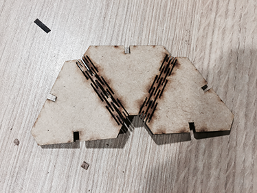
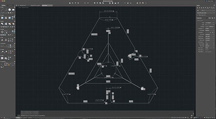
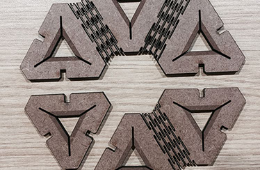
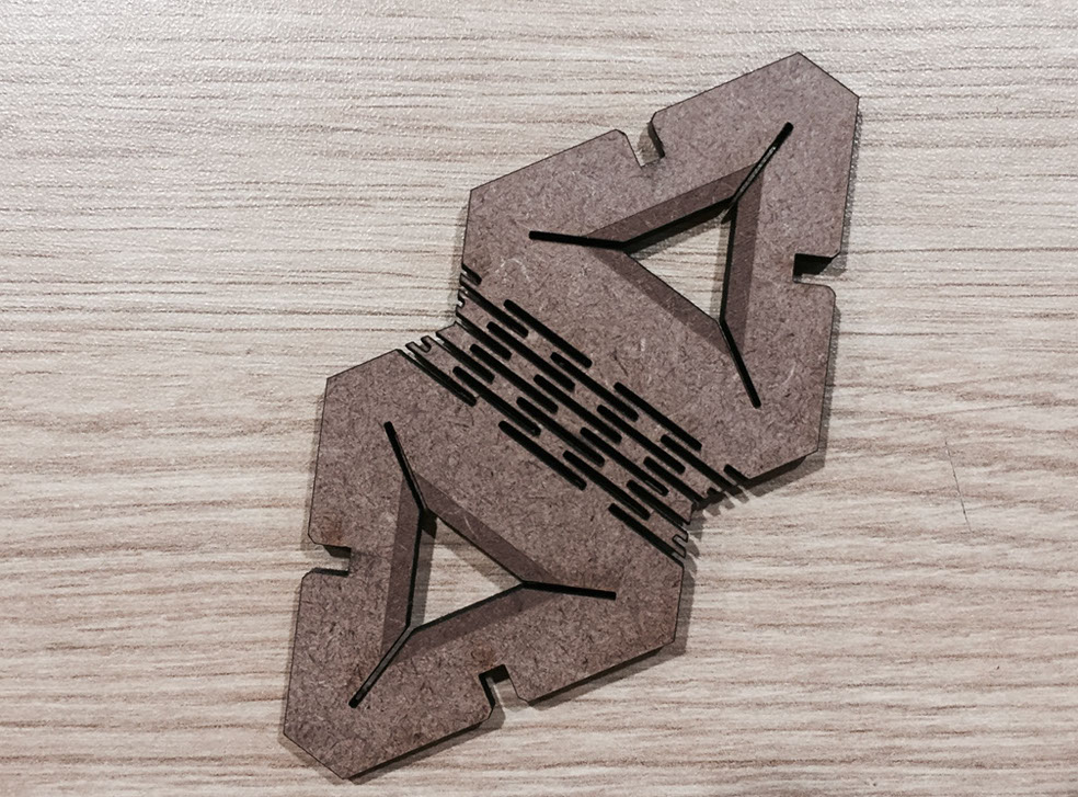
Finally I tried a piece with eight stripes, I realized that the more stripes the piece had, the more flexible it became and the more resistance it lost. So I looked for an amount that would balance flexibility and endurance. It worked much better, so I added two modular pieces and more detail.
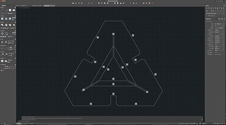
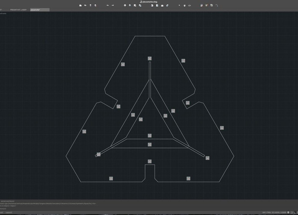
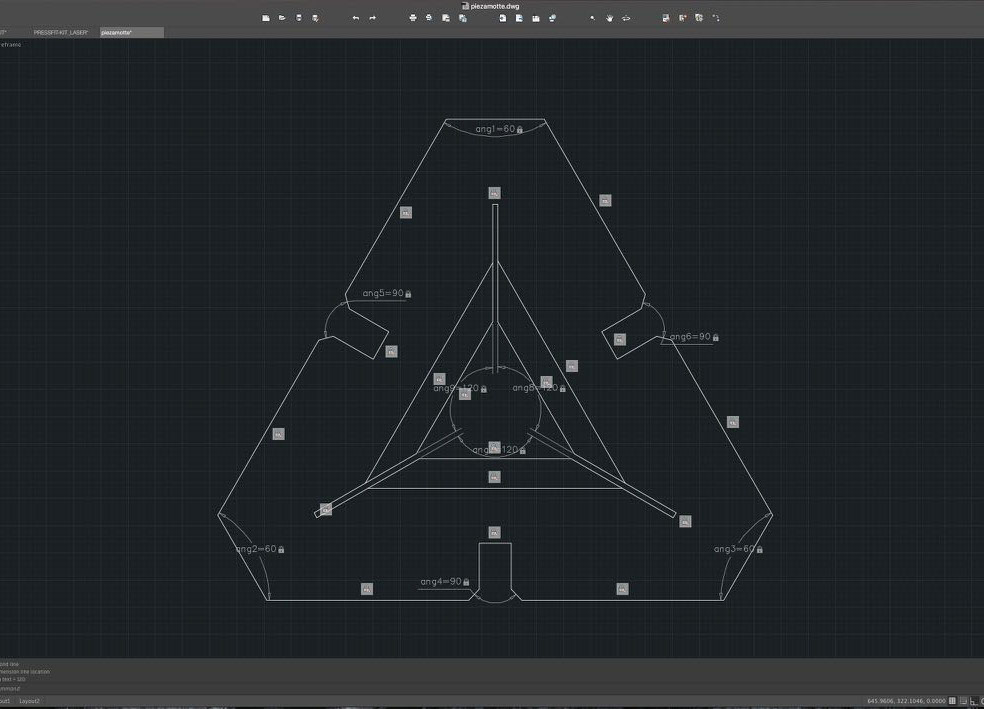
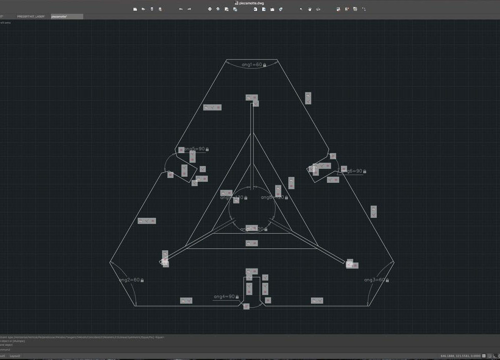
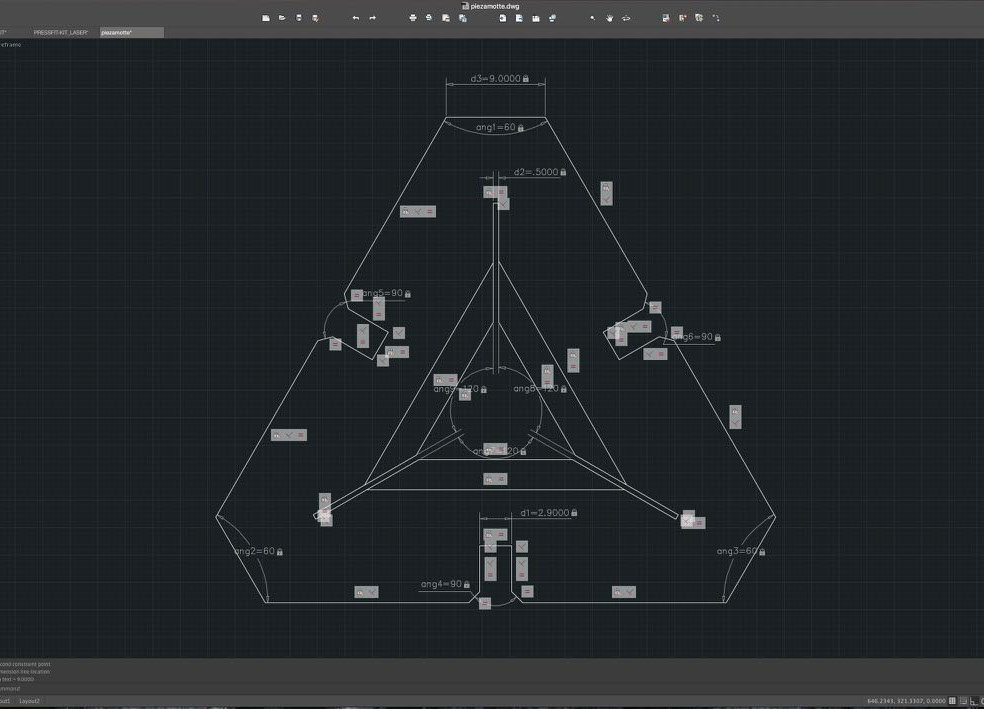
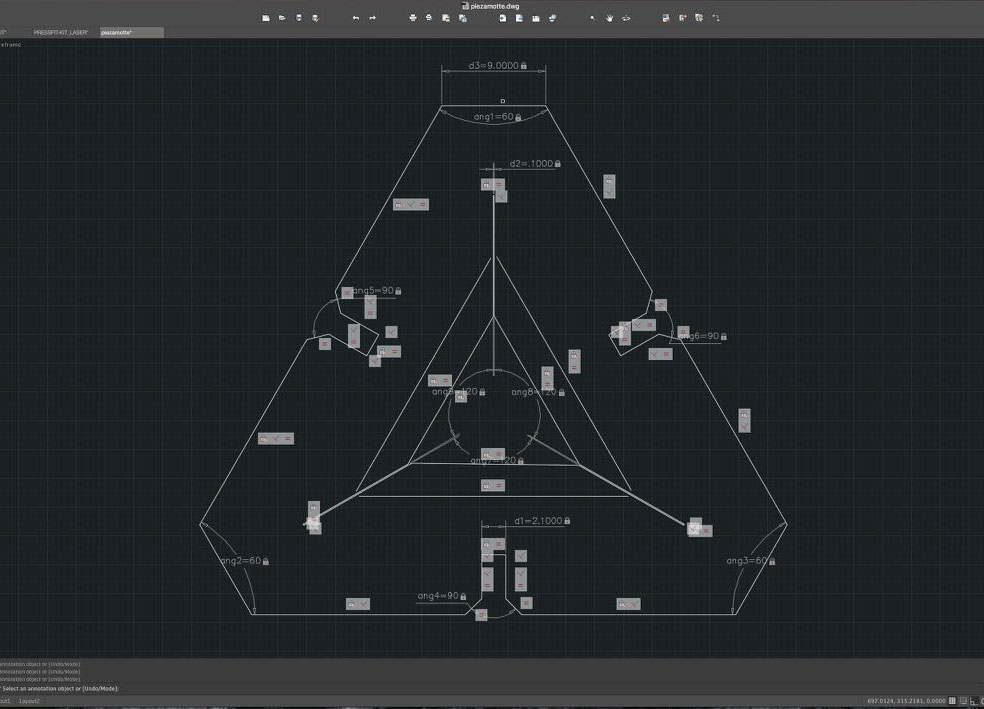
For the final piece, I tried the parametric design again, only this time I defined a parameter order. First the points that will not change position (geometrical constrains fix), then the angles (dimensional constrains angular), the the lines (geometrical constrains equal and perpendicular) and finally the distances that I might want to change (dimensional constrains linear). The idea was that if you had to modify the piece for another material, you could change the joints measures quickly and practically.
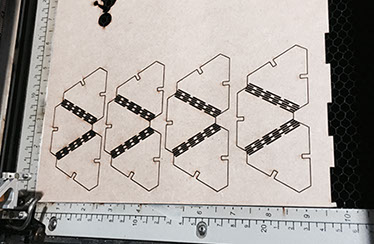
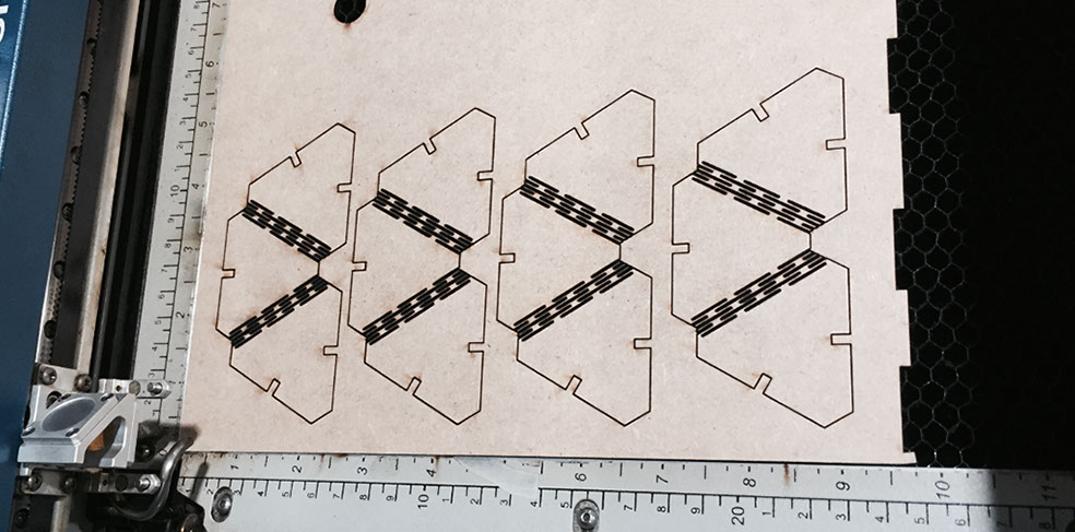
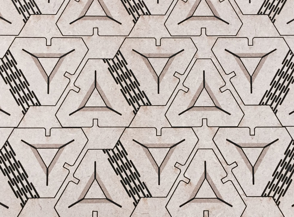
I saved the pieces on a .dxf format and import them to cut in Corel Draw, preparing the file for a format of 0.60m long by 0.30m high and 3mm thick.
The settings for the lasercutter were: for raster 100% speed and 100% power, for vector 16% speed, 100% power and 500Hz frequency. I had to slightly modify the cutting parameters we defined in the group task due to the complexity of the piece. The articulation bands needed less speed and more power to be cut in a single pass.
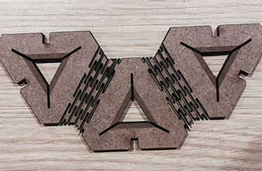
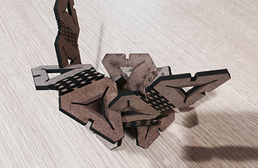
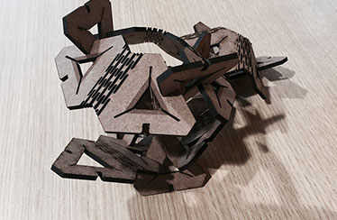
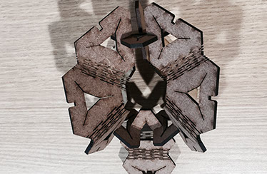
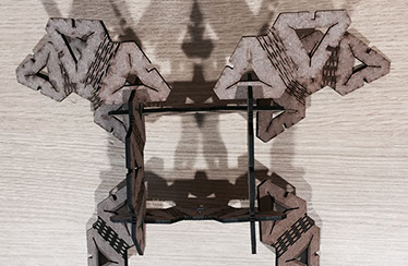
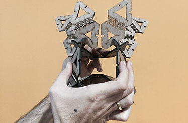
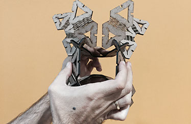
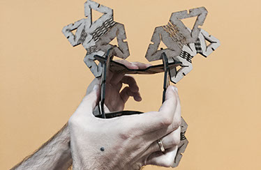
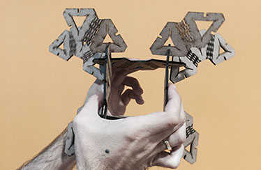
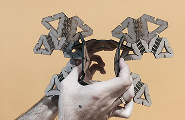
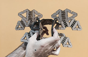
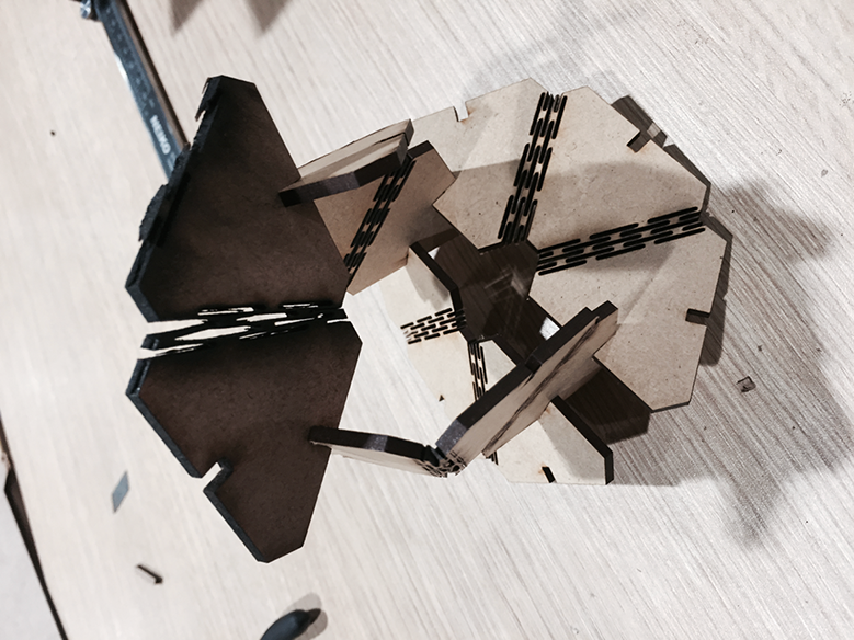
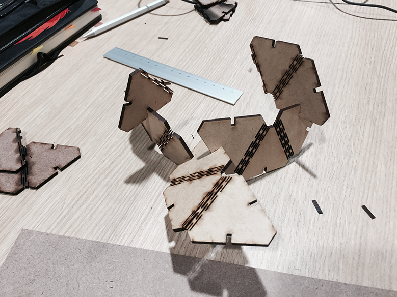
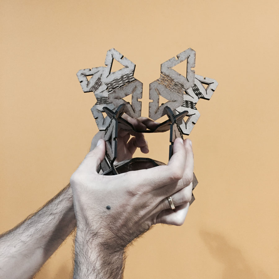
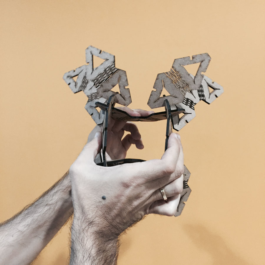
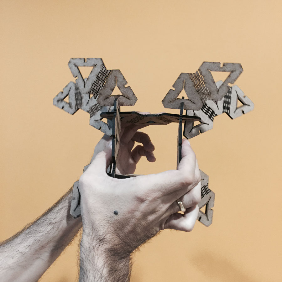
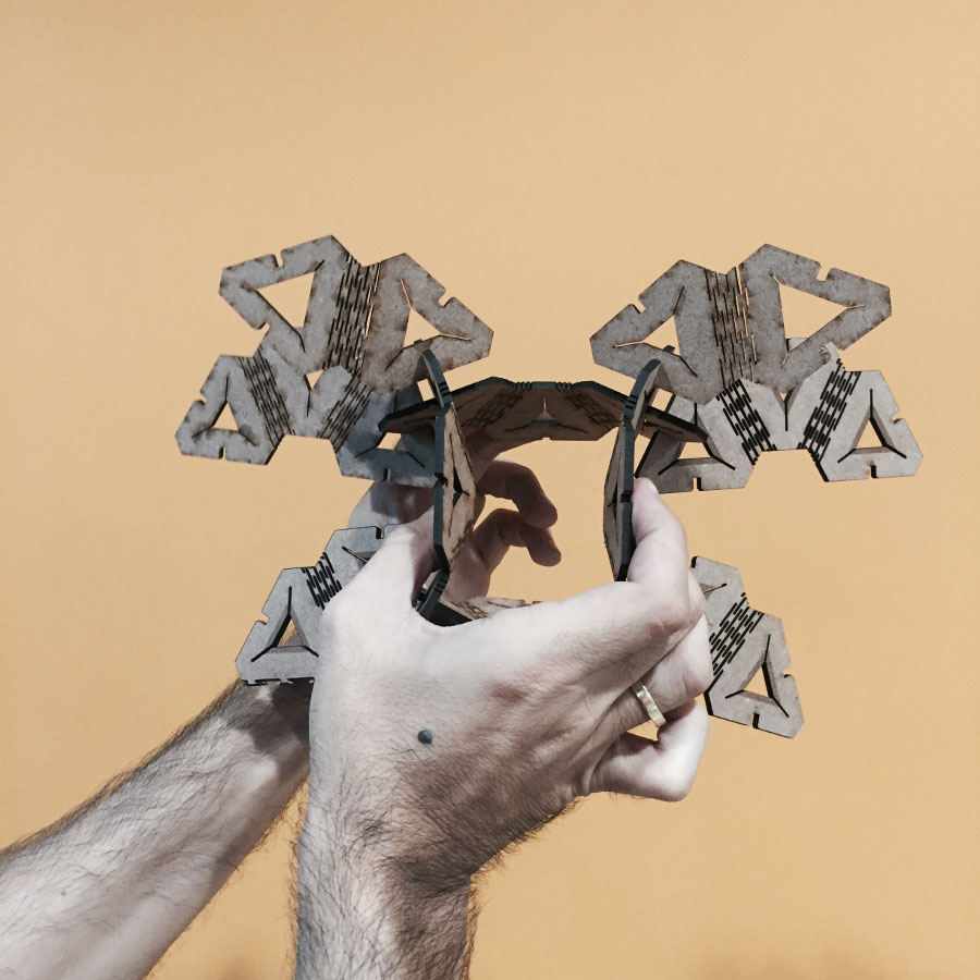
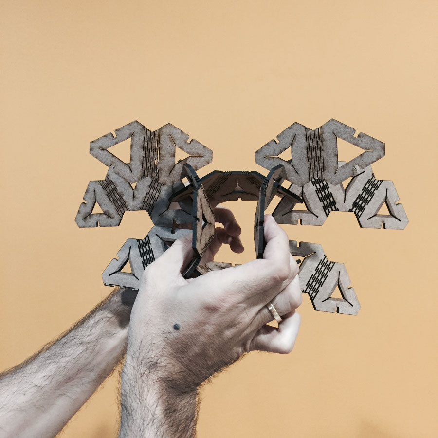
With the Press Fit Construction Kit, I began to make some shapes, a bunny, a bulldog, a flower and even a butterfly
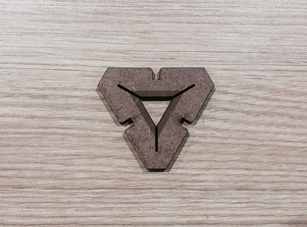
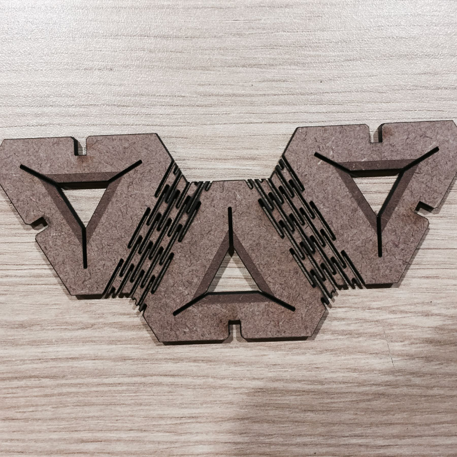
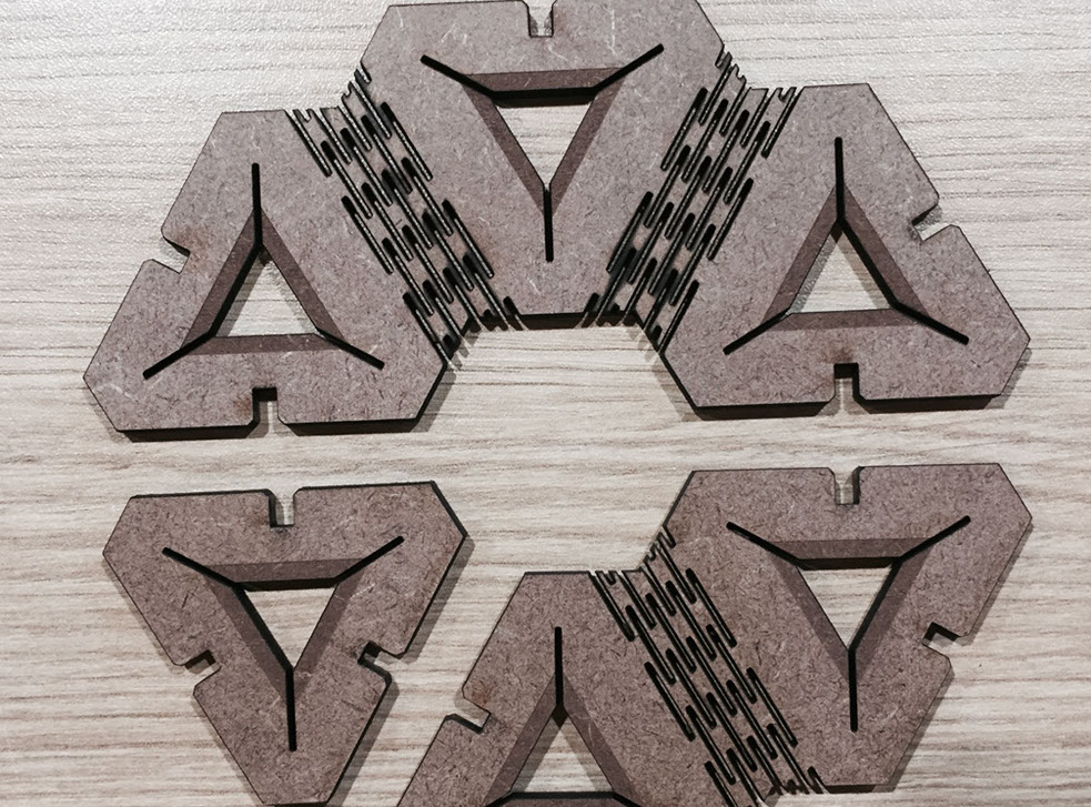
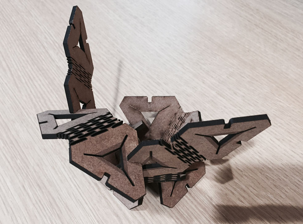
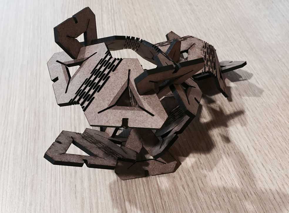
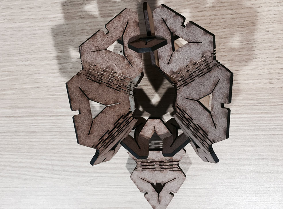
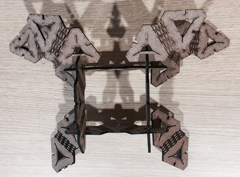
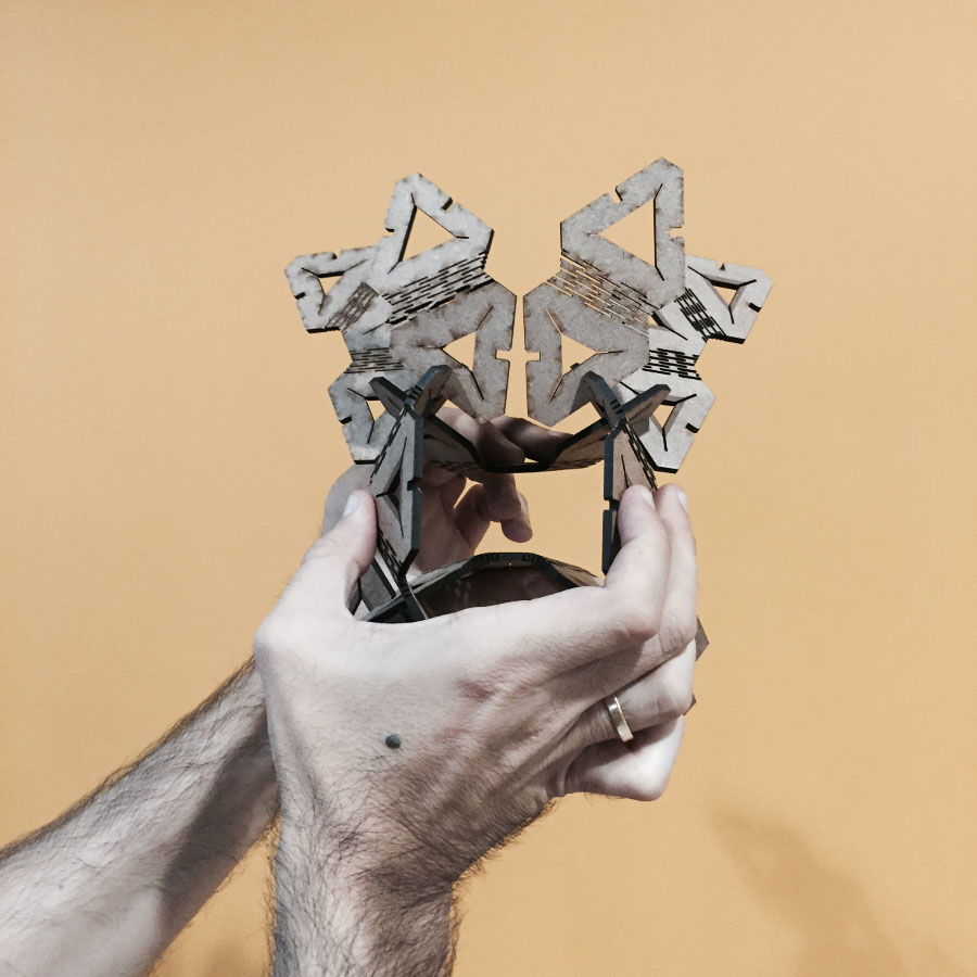
But something unexpected happened, the articulation that was designed to give versatility, also gave movement to the piece.
xmottex@gmail.com