ELECTRONICS DESIGN
WEEK 6
- Redraw the echo hello-world board, add (at least) a button and LED (with current-limiting resistor) check the design rules, make it, and test it
- Extra credit: simulate its operation
- Extra credit: measure its operation
REDRAW THE ECHO HELLO-WORLD BOARD
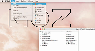
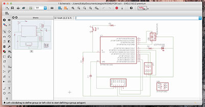
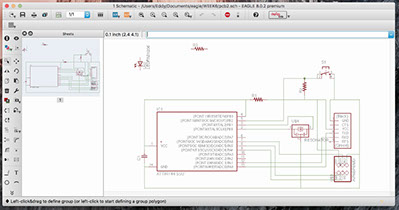
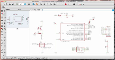
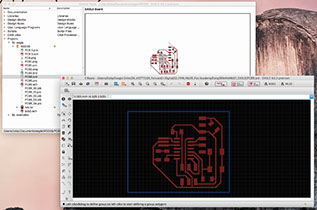
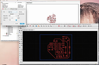
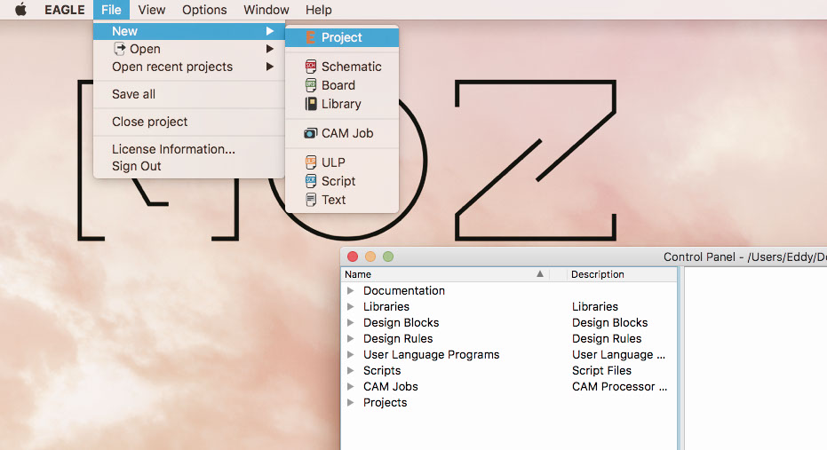
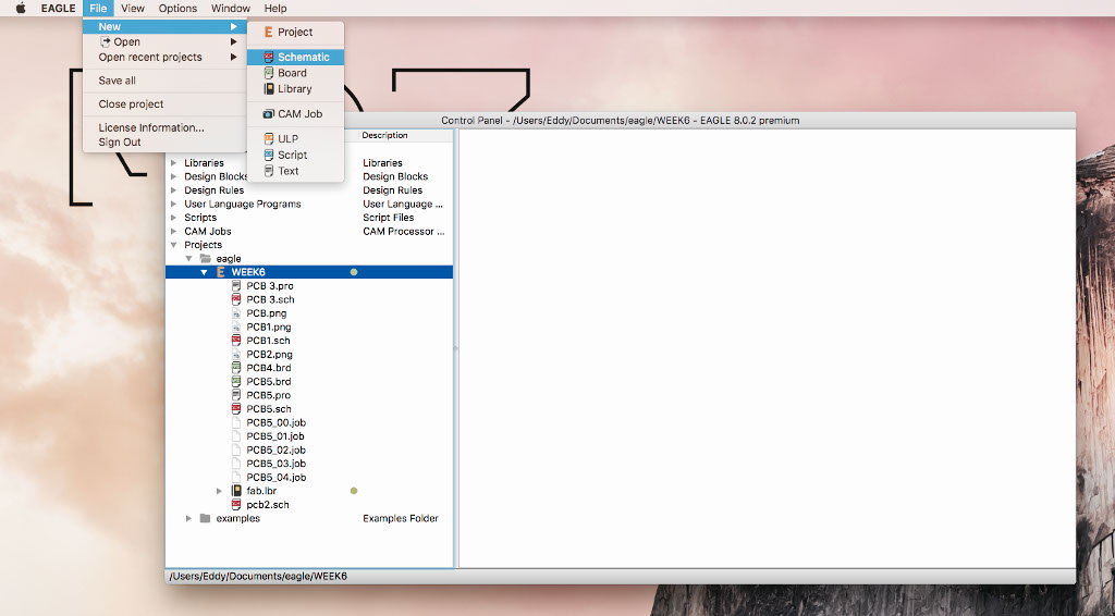
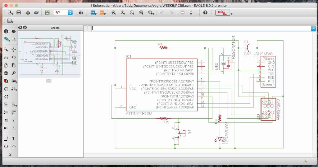
In order to redraw the echo hello-world board, i used Eagle from Autodesk. I redraw the board schematic adding a button and LED. Until I finally understand the program and the board I drew up to four schematics. A schematic is a part of an Eagle project (electronic project), is the first part of the design. There with the add command, you begin to set the components that should have your PCB, and with the net command you interconect them. I drew up four schematics, because I didn't find the right order of conections. When you have your schematic ready, you have to select the Switch to board icon, which leads to a presentation where to properly design the board. Here you specify the width of the tracks and the size of the pads. I used a 0.025 inch grid and 0.016 inch width for the tracks.
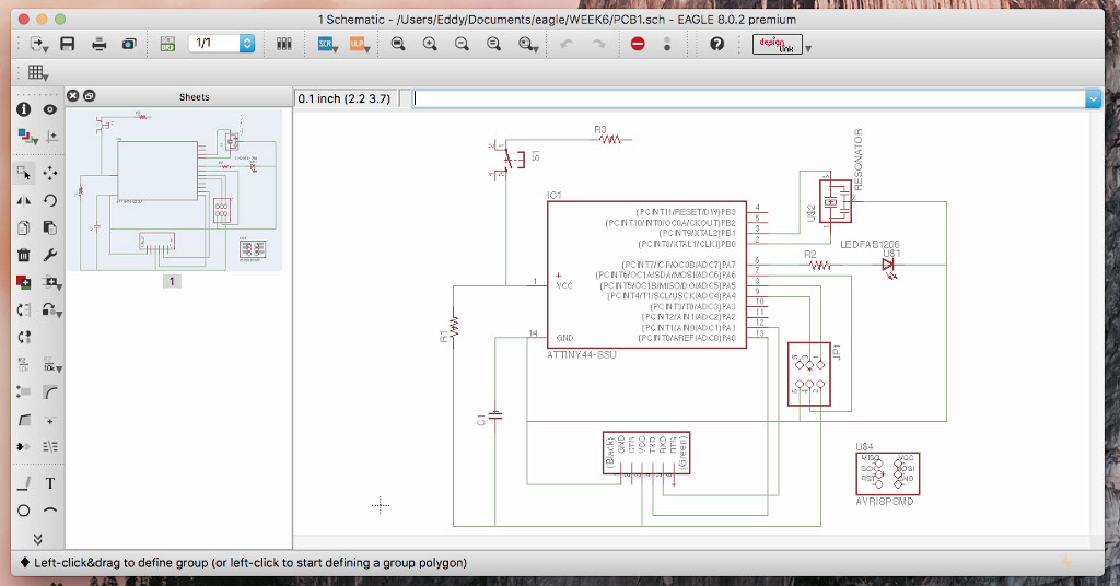
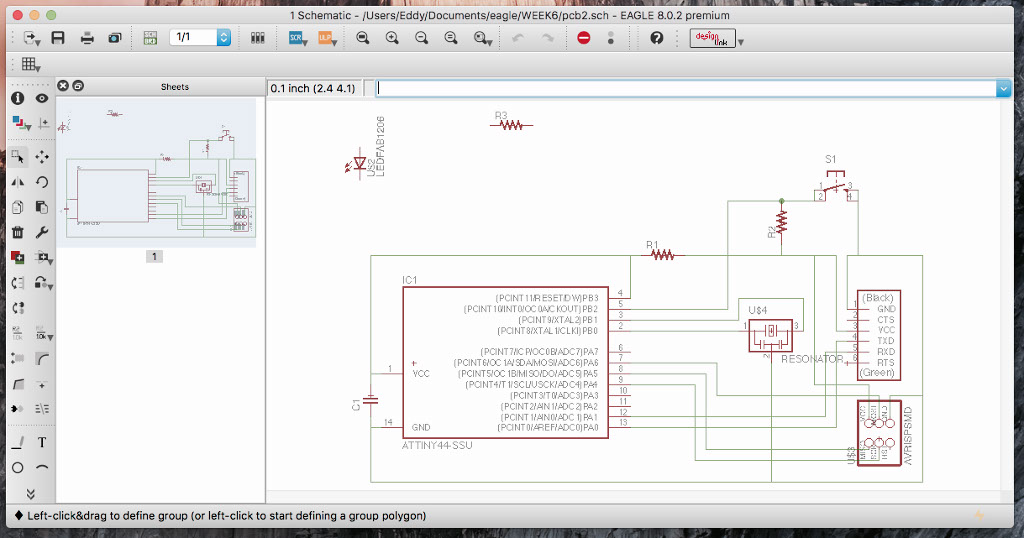
SCHEMATIC FILE
BOARD FILE


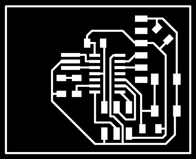
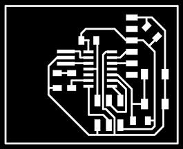
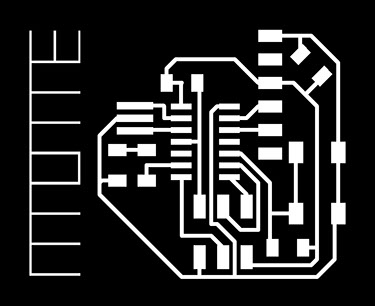
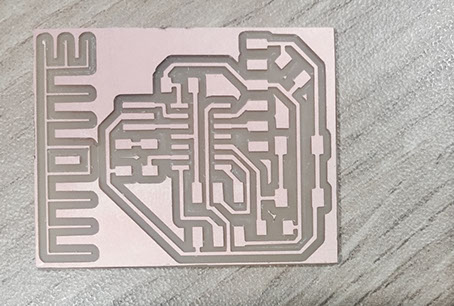
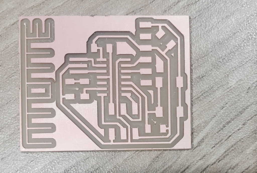
When the layout scheme and board were ready, I proceeded to export the .png black and white image for the MODELA MDX-20. In fact, if you know the components and dimesions well, it is possible to design the PCB with simple drawing software like paint, or with a slightly more elaborate one like Photoshop. After generating the .png image, I used photoshop to add my personal logo and to prepare both images, traces and interior. Then I mill the board in the MODELA. But I should have taken into account the width of the logo, because the lines were very thin.

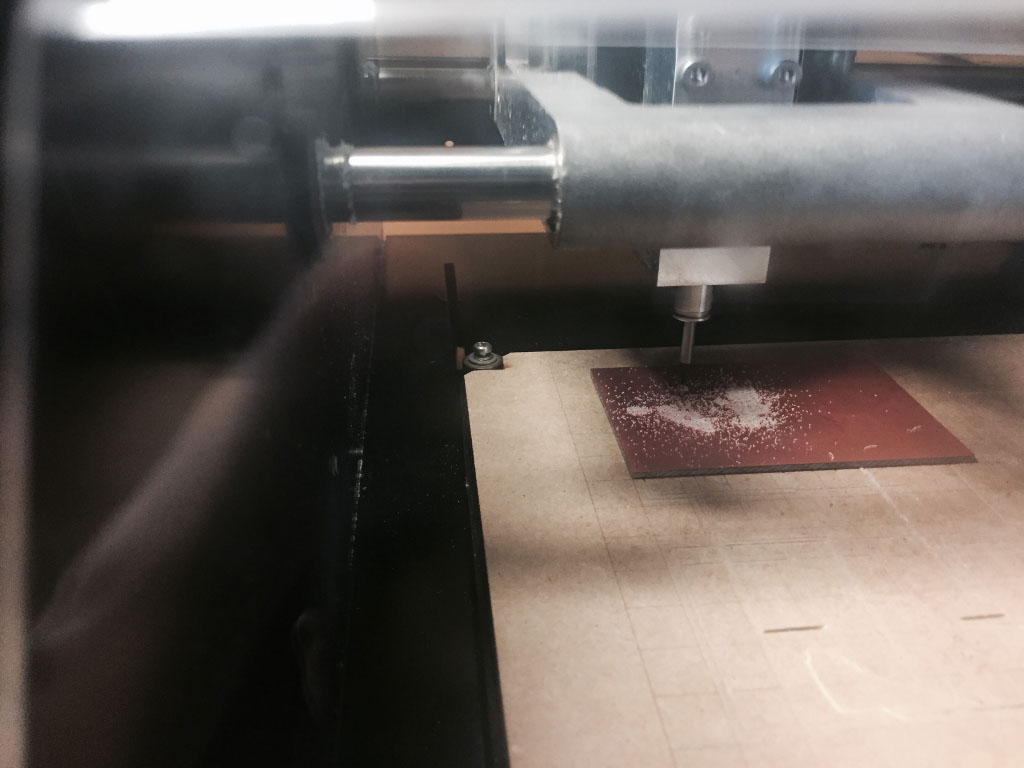
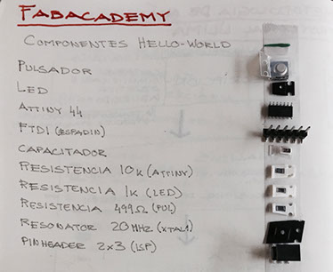
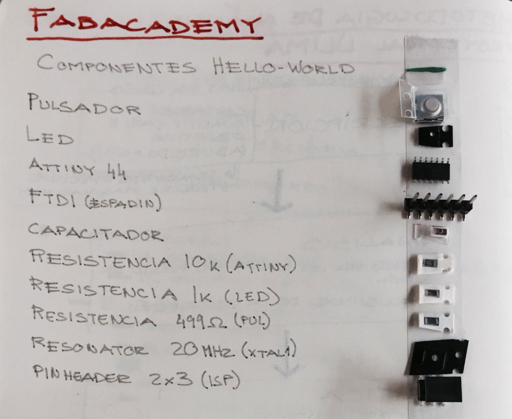
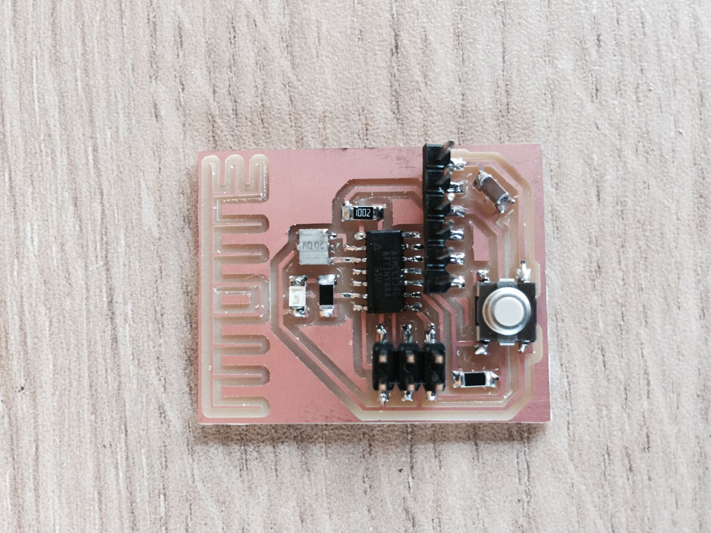
When the milling was finished, I requested the components to build the board and soldered them. I burn the bootloader to the board with the ISP we make on the fourth week (electronics production assignment) and a FTDI(3,3v) cable. The software we used was ARDUINO IDE, wich has his own programing lenguage.
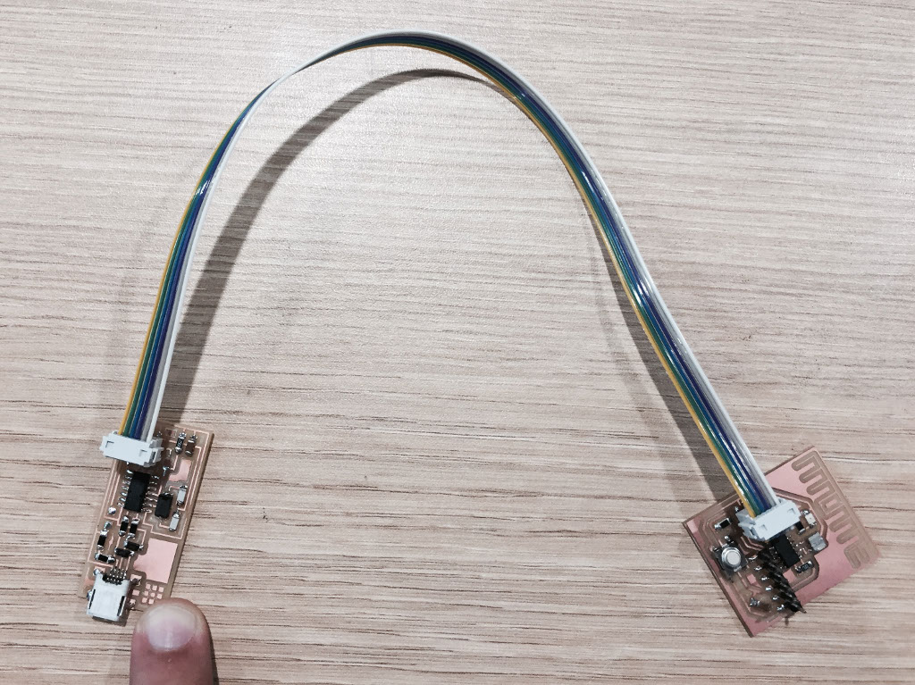
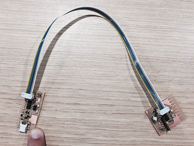
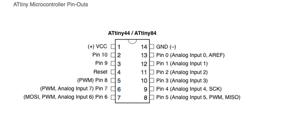
To burn the bootloader, i needed to identify the port in wich the FTDI cable was pluged, then in the tool tab, begin to set the information, board, processor, port, clock and programmer. Then I wanted the led light always on and turn it off every time I pressed the button. For that I looked for the table of equivalences between the ATtiny and the Arduino, so I can choose the right pins. After that I made the code on the Arduino IDE and test the board.
ARDUINO FILES


xmottex@gmail.com