Embedded programming
1. Week assignment
- read a microcontroller data sheet
- program your board to do something, with as many different programming languages and programming environments as possible
2. Development Environment
I used Arduino IDE and GCC (using atom text editor).
3. Arduino IDE
You can use Arduino IDE to program the hello world board.
First, you have to add the AtTiny family boards in the IDE.
Go to Files → Preferences and in the field “Additional Boards Manager URLs” paste
https://raw.githubusercontent.com/damellis/attiny/ide-1.6.x-boards-manager/package_damellis_attiny_index.json
IDE then may prompt you to update definitions for boards and library, so follow the instruction to update them. Then you need to install the attiny board package.
Go to Tools → Boards → Board Manager → in the search field type “attiny” → a single result will appear → click on install in this package.
You can now select the Attiny family in boards.
Go to Tools → Boards → choose Attiny24/44/84
Choose the right processor now (the Hello World Board i’m using runs an Attiny44) with a 20MHz external clock.
Go to Tools → Processor→ choose Attiny44
Go to Tools → Clock → External 20 MHz
Choose the right COM port (it depends on the system)
On programmer choose USBTinyISP (we are using the FabISP made in electronic production week)
Go to Tools → Programmer→ USBTinyISP
You can now burn the bootloader to the board (the bootloader is a tiny program that let you run other programs).
The first sketch I made is for blinking a LED (based on arduino example to see if my board is effectively working).
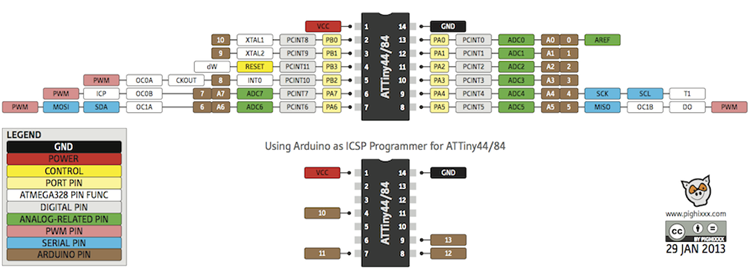
In the above image you can see the corresponding Attiny pinout - Arduino pin number.
My LED is soldered on ADC7, corresponding to pin 7.
This is the blink code.
          int led = 7; // the pin where the led is soldered
          // the setup function runs once when you power on the board
          void setup() {
            // initialize pin “led” as an output.
            pinMode(led, OUTPUT);
          }

          // the loop function runs over and over again forever
          void loop() {
            digitalWrite(led, HIGH);   // turn the LED on (HIGH is the voltage level)
            delay(500);                       // wait for a half second (500ms)
            digitalWrite(led, LOW);    // turn the LED off by making the voltage LOW
            delay(500);                       // wait for a half second (500ms)
          }
Next I moved to use the the IDE to read the temperature via serial.
To read the temperature you need to use the Steinhart–Hart equation.
          #include <math.h>

          int led = 7;
          int adc = 2;
          int th = 35;
          double Thermistor(int RawADC) {
            double Temp;
            Temp = log(10000.0/(1024.0/RawADC-1)); // for pull-up configuration
            Temp = 1 / (0.001129148 + (0.000234125 + (0.0000000876741 * Temp * Temp ))* Temp );
            Temp = Temp - 273.15;            // Convert Kelvin to Celcius
            return Temp;
          }


          // the setup function runs once when you press reset or power the board
          void setup() {
            pinMode(led, OUTPUT);
            pinMode(adc, INPUT);
          }

          // the loop function runs over and over again forever
          void loop() {
            if(int(Thermistor(analogRead(adc)))>th){
              digitalWrite(led, HIGH);
            }
            else{
              digitalWrite(led, HIGH);
            }
          }
4. GCC compiler
4.1 Overview of AtTiny registers
- DDR handle the direction of the pin ( 0 = input, 1 = output)
Note: DDRA for port group A and DDRB for port group B
- PORT is about the port state:
if DDR is output, writing 1/0 sets pin as HIGH/LOW
if DDR is input, writing 1/0 sets turn on/off internal pull-up resistor.
- PIN let you read the pin value
Concerning ADC, we use different registers:
- ADMUX
| REFS1 | REFS0 | MUX 5 | MUX4 |MUX3 | MUX2 | MUX1 | MUX0 |
Where:
- REFS1-2 let you set the adc reference voltage
- ADLAR is left/right alignment
- MUX registers are the input pin associated with conversion
- ADCSRA
| ADEN | ADSC | ADATE | ADIF | ADIE | ADPS2 | ADSP1 | ADSP0
Where:
- ADEN, ADC Enable
- ADSC, ADC Start Conversion
- ADATE, to let the ADC sample using an external input clock
- ADIF, ADC Interrupt Flag
- ADIE, ADC Interrupt Enable
- ADPS registers set the ADC clock frequency
4.2 Led blink C code
          #include <avr/io.h>
          #include <util/delay.h>

          int main(void){
            DDRA |= (1<<PCINT7); //setting pin 7 of port a as output.
            while(1){
              PORTA |= (1<<PCINT7); //setting the pin 7 high
              _delay_ms(1000); //1000ms delay
              PORTA &= ~(1<<PCINT7); // setting the pin 7 low
              _delay_ms(1000); //1000ms delay
            }
          }
This code does the same thing of Arduino, except that, the delay is longer than 1 second.
To fix this you need to add clock divider:
          CLKPR = (1 << CLKPCE);
          CLKPR = (0 << CLKPS3) | (0 << CLKPS2) | (0 << CLKPS1) | (0 << CLKPS0);
So the full code becomes:
          #include <avr/io.h>
          #include <util/delay.h>

          int main(void){
            // set clock divider to /1
            //
            CLKPR = (1 << CLKPCE);
            CLKPR = (0 << CLKPS3) | (0 << CLKPS2) | (0 << CLKPS1) | (0 << CLKPS0);
            DDRA |= (1 << PCINT7); //setting pin 7 of port a as output.
            while(1){
              PORTA |= (1 << PCINT7); //setting the pin 7 high
              _delay_ms(1000); //1000ms delay
              PORTA &= ~(1 << PCINT7); // setting the pin 7 low
              _delay_ms(1000); //1000ms delay
            }
          }
4.3 Thermistor temperature read
References for temperature conversion;
http://playground.arduino.cc/ComponentLib/Thermistor2
            #include <avr/io.h>
            #include <math.h>
            #include <avr/interrupt.h>
            #include <util/delay.h>

            int main(void){
              int temp, th = 30;
              uint8_t ADCLow;
              uint16_t ADCFull;
              DDRA |= (1 << PCINT7); //setting pin 7 of port a as output.
              ADMUX |= (0 << REFS0); // set the voltage reference
              ADMUX |= (0 << REFS1); //
              ADMUX |= (0 << ADLAR); // left adjust the result
              ADMUX |= (0 << MUX3) | (0 << MUX2) | (1 << MUX1) | (0 << MUX0); // select the ADC pin ADC2 PA2
              ADCSRA |= (1 << ADEN); // Enable ADC
              ADCSRA |= (1 << ADPS2) | (1 << ADPS1) | (1 << ADPS0); // prescaler to 128
              // set clock divider to /1
              //
              CLKPR = (1 << CLKPCE);
              CLKPR = (0 << CLKPS3) | (0 << CLKPS2) | (0 << CLKPS1) | (0 << CLKPS0);
              while(1)
              {
                ADCSRA |= (1 << ADSC); // Start the conversion
                while (ADCSRA & (1 << ADSC)); // Wait till the conversion is done
                ADCLow = ADCL; // get the ADCL 8 bits
                ADCFull = (ADCH<<8 | ADCLow) / 4;
                temp = log(10000.0/(1024.0/ADCFull-1)); // Steinhart-Hart Thermistor Equation
                temp = 1 / (0.001129148 + (0.000234125 + (0.0000000876741 * temp * temp ))* temp );
                temp = temp - 273.15;            // Convert Kelvin to Celcius
                if(temp>th){ //if temperature is higher than threshold, light led
                  PORTA |= (1 << PCINT7); //setting the pin 7 high
                }
                else{
                  PORTA &= ~(1 << PCINT7); // setting the pin 7 low
                }
              }
            }
This code does the same as the Arduino sketch.
4.3 Pushing code to board
Now that you have your sources, you can push them to the board.
We use a file called “makefile”, that contains all the directive to build the program.
I used the Neil’s makefile downloadable from archive.
The lines in the beginning are the most important:
            PROJECT=adc
            SOURCES=$(PROJECT).c
            MMCU=attiny44
            F_CPU = 20000000
Project is your .c file name, without extension, mmcu the IC you are using, and the f_cpu the clock frequency at which he is running.
From a terminal, move to the directory containing the .c and .make file and then run;
            make -f makefile.make
            make -f blinkled.make program-usbtiny-fuses
            make -f blinked.make program-usbtiny
5. Conclusion
Programming an AtTiny is not an immediate task: you need to study the datasheet and understand what registers do.
Using Arduino IDE is easier, but it has some downside: using bootloader you need plenty of space more and you have less control on what happens in the board.
6. Files
Source codes - .zip
Update
It's possible to find more work about this week on the final project page in the related development section