Networking and communications
1. Week assignment
design and build a wired &/or wireless network connecting at least two processors
2. Development enviroment
This week I used Arduino IDE and Fritzing for drawing the schematics.
3. The I2C protocol
For this week I decided to use the I2C (Inter Integrated Circuit).
The I2C is a communication protocol, which uses only two lines: SDA (Serial Data Line) and SCL (Serial Clock Line); it’s a clocked serial line, basically.
Its distinctive trait is that every device is connected to the same bus: everyone has got a specifical address.
Normally there is a master device, and other slave devices: the master decides to which one he’s “talking to” based on the slave address. so it let you connect a wide variety of devices.
As from I2C specification, at least one device in the bus must have pull-up resistor on the two lines.
4. The implementation
I used two Arduinos (one acting as a master and one acting as a slave) and a BMP180 temperature sensor: the master reads the data from the sensor (an I2C device itself) and send the readings to the slave, who writes the actual temperature and pressure on the serial line, read from the Arduino IDE serial monitor.
4.1 The circuit
For the circuit I made I used a breadboard.
Note: the lines in a breadboard are parallel (respect to the center of the breadboard) for the + and -, used for the power supply (usually), while in the other holes are perpendicular.
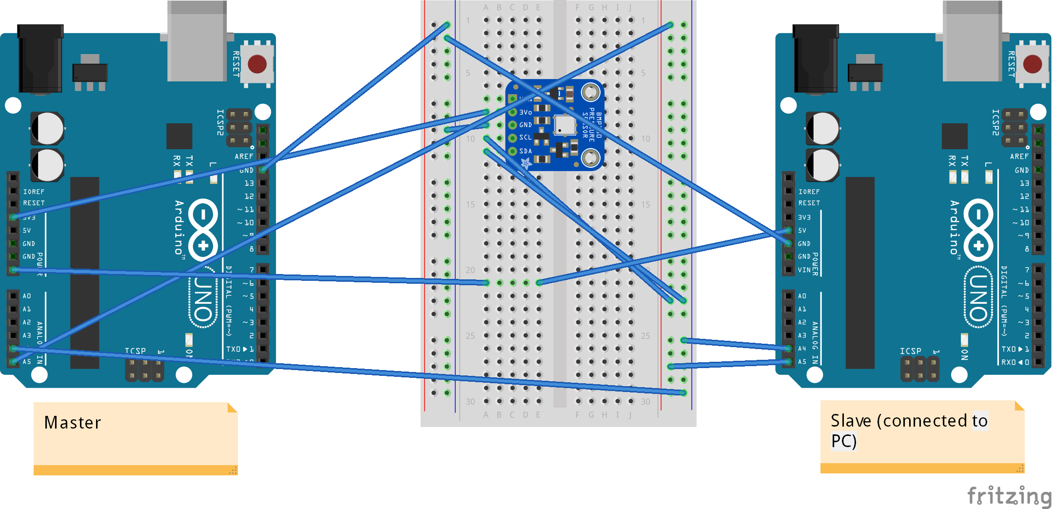 Breadboard view
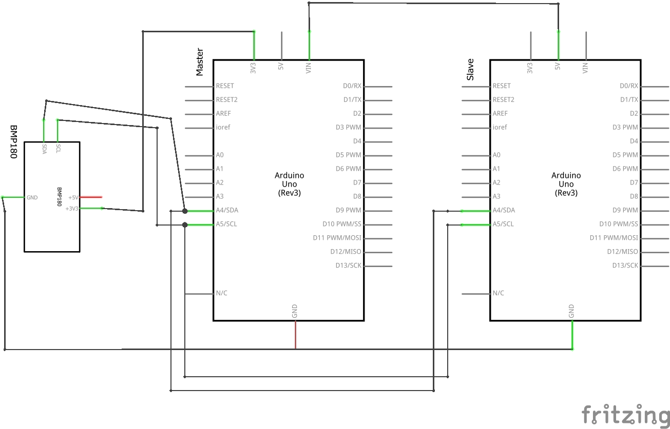 Schematic view
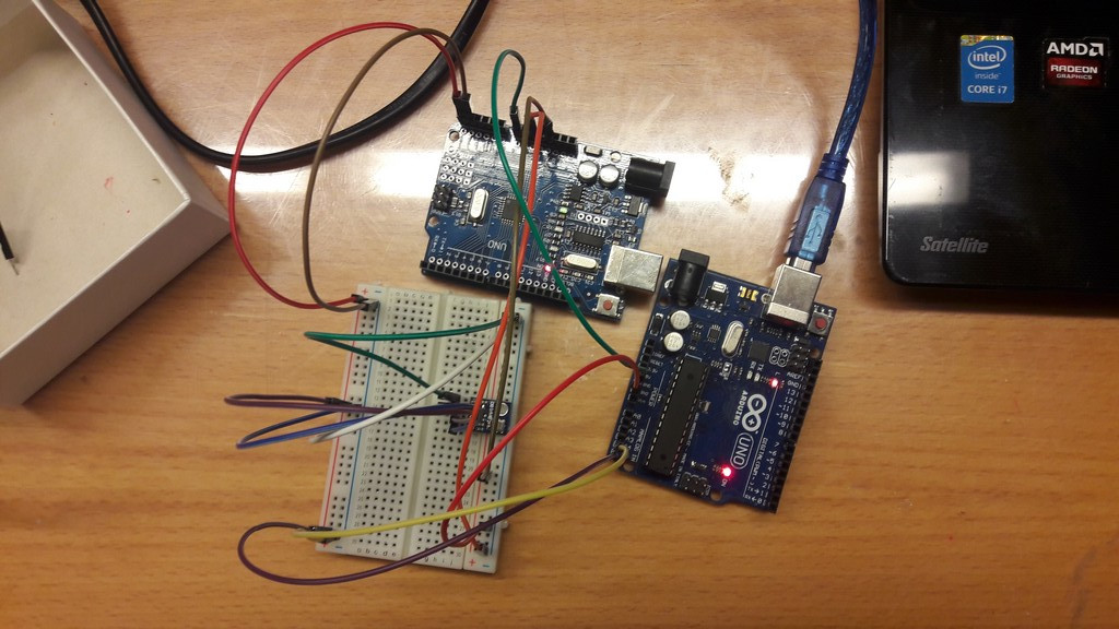 And a messy photo!
If you want to use I2C with arduino, the 2 pins you have to use are A4 for SDA and A5 for SCL.
As you can see, the slave is connected to the PC and powers up the master: it can do this if not a lot of things are attached to the master (if it drains too much current it may stop working or have strange behaviours).
An important note is on the ground line: if you connect more than one microcontroller together, they MUST share the same line.
Some issues rises when devices with the same address connect to the bus: this problem is avoidable in the Arduinos because you assign an ID to every one (this ID is optional for the master).
4.2 The master code
            #include <SFE_BMP180.h> //temp sensor library
            #include <Wire.h> //wire library, needed for i2c comm

            // Create an SFE_BMP180 object
            SFE_BMP180 sensor;

            void setup() {
              Wire.begin(); //join i2c bus (address optional for master)
              Serial.begin(9600); //inizialize serial
              //initialize sensor
              if (sensor.begin())
              Serial.println("BMP180 init success");
              else {
                Serial.println("BMP180 init fail\n\n");
                while (1); // Pause forever.
              }
            }

            void input2i2c(double temp, double pressure) {
              byte Data[16];
              byte Temp[8];
              byte* tempptr = (byte*) &temp;
              byte* pressureptr = (byte*) &pressure;
              Data[0] = tempptr[0];
              Data[1] = tempptr[1];
              Data[2] = tempptr[2];
              Data[3] = tempptr[3];
              Data[4] = tempptr[4];
              Data[5] = tempptr[5];
              Data[6] = tempptr[6];
              Data[7] = tempptr[7];
              Data[8] = pressureptr[0];
              Data[9] = pressureptr[1];
              Data[10] = pressureptr[2];
              Data[11] = pressureptr[3];
              Data[12] = pressureptr[4];
              Data[13] = pressureptr[5];
              Data[14] = pressureptr[6];
              Data[15] = pressureptr[7];
              //Serial.write(Data, 16); DEBUG
              Wire.beginTransmission(8); // transmit to device 8
              Wire.write(Data,16);
              Wire.endTransmission();    // stop transmitting
              // DEBUG
              //Serial.println();
              //for (int i = 0; i < 8; i++) {
                //  Temp[i] = Data[i];
                //}
                //Serial.println((float&)Temp); //DEBUG
              }

              void loop() {
                char status;
                double T, P;
                //temp read
                status = sensor.startTemperature();
                if (status != 0) {
                  // Wait for the measurement to complete:
                  delay(status);
                  // Retrieve the completed temperature measurement:
                  status = sensor.getTemperature(T);
                  if (status != 0) {
                    //DEBUG Print out the measurement:
                    //Serial.print("Temperature: ");
                    //Serial.print(T, 2);
                    //Serial.println(" deg C");

                  }
                }
                //pressure read
                status = sensor.startPressure(3);
                if (status != 0) {
                  // Wait for the measurement to complete:
                  delay(status);
                  // Retrieve the completed pressure measurement:
                  status = sensor.getPressure(P, T);
                  if (status != 0) {
                    // DEBUG: Print out the measurement:
                    //Serial.print("Absolute pressure: ");
                    //Serial.print(P, 2);
                    //Serial.println(" mb");
                    input2i2c(T,P);
                  }
                }
                delay(2000);
              }
The interesting parts in this code is the input2ic function: it generates a 16 byte vector and write it in the i2c bus; if you want to send variables type you need to send it byte to byte.
So, every byte of the float variables holding the temperature and the pressure are written to a byte array (you can’t do this automatically).
The advantage of transmitting byte to byte is that you can implement your own dictionary for the communication.
The upcasting must be done on the slave.
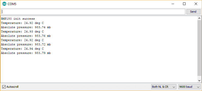
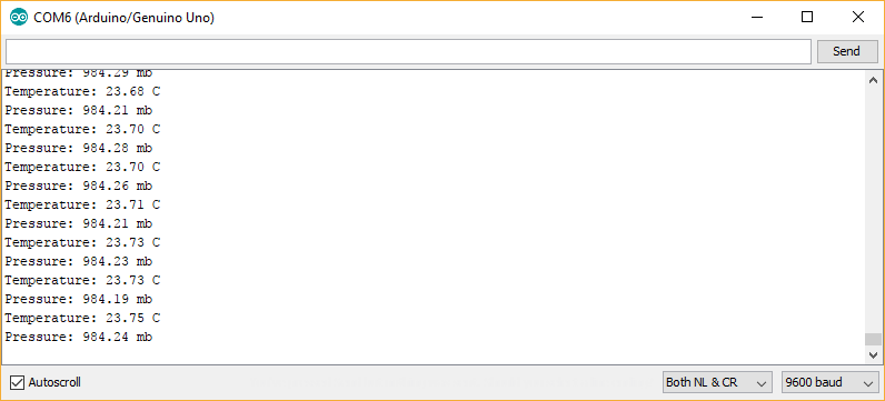
In the debug code, now commented, I printed the output (managed by its library) from the sensor, to see if it was working or not; here’s a screenshot:
4.3 The slave code
              #include <Wire.h>
              byte received[16];
              byte Temp[8], Pressure[8];
              void setup() {
                Wire.begin(8);                // join i2c bus with address #8
                Wire.onReceive(receiveEvent); // register event
                Serial.begin(9600);           // start serial for output
              }

              void loop() {
                delay(10);
              }

              // function that executes whenever data is received from master
              // this function is registered as an event, see setup()
              void receiveEvent(int howMany) {
                int i=0;
                while (Wire.available()) { // loop through all but the last
                  received[i]= Wire.read(); // receive byte
                  i++;
                }
                for (int i = 0; i < 8; i++) {
                  Temp[i] = received[i];
                }
                for (int i = 8; i < 15; i++) {
                  Pressure[i-8] = received[i];
                }

                Serial.print("Temperature: ");
                Serial.print((float&)Temp);
                Serial.println(" C");
                Serial.print("Pressure: ");
                Serial.print((float&)Pressure);
                Serial.println(" mb");
              }
This code is much simpler.
As you can see this is interrupt driven: in the loop there is nothing (interrupt means that when an event happens something is done; in the case the event is that some data is written on the bus).
As said above, the data is read byte to byte and then casted to a float to be written in the serial line, linked to the PC.
5. Files
Source codes and schematics - .zip
Update
On my instructor request I linked two boards I made (the hello world board and the input device board).
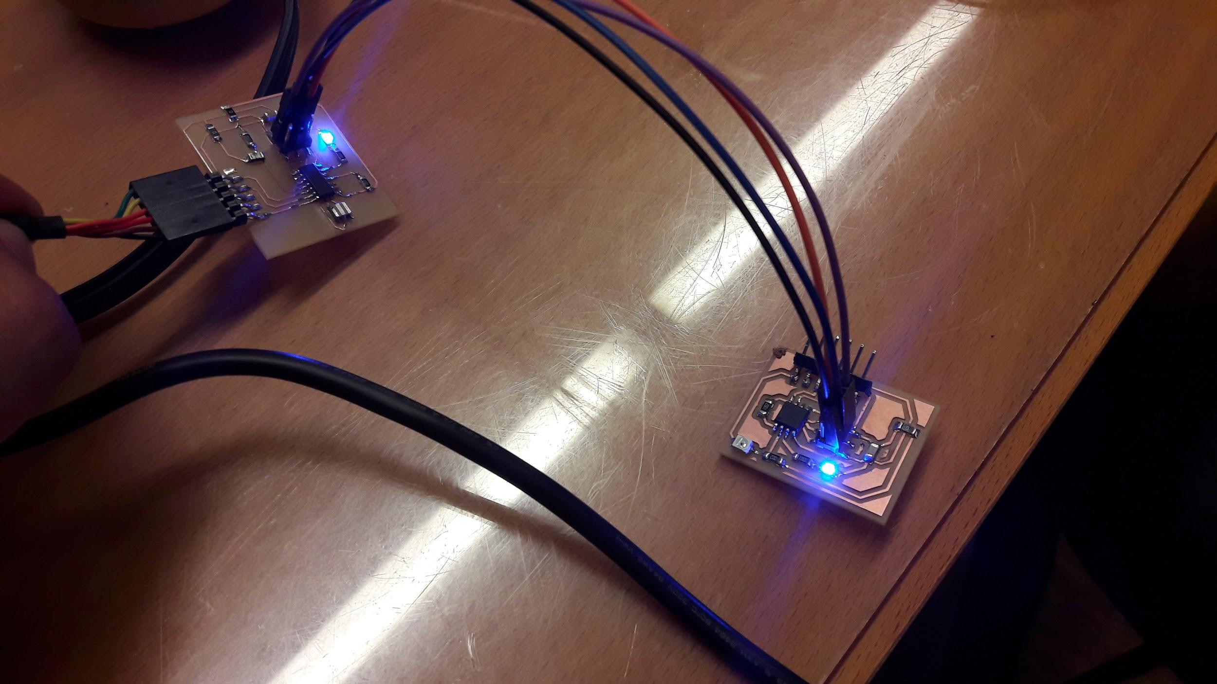
FDTI cable attached to AtTiny44, attached to AtTiny85 via I2C
At first I programmed the AtTiny85 board to use the I2C protocol, as slave device
              #define I2C_SLAVE_ADDRESS 0x8 // Address of the slave

              #include < TinyWireS.h >

              #define ADC3 A3

              void setup() {
                TinyWireS.begin(I2C_SLAVE_ADDRESS); // join i2c network
                TinyWireS.onRequest(requestEvent);
                pinMode(4,OUTPUT);
                digitalWrite(4,HIGH);
                pinMode(ADC3, INPUT_PULLUP);
              }

              void loop() {
                // This needs to be here
                TinyWireS_stop_check();
              }

              // Gets called when the ATtiny receives an i2c request
              void requestEvent() {
                int val=analogRead(ADC3);
                byte valLow = val & 0xff;
                byte valHigh = (val >> 8);
                TinyWireS.send(valHigh);
                TinyWireS.send(valLow);
              }
This sketch let the board send as 2 bytes (valHigh & valLow) the value read from the ADC.
It’s not possible to send an int using tinywires, so you need to split the result.
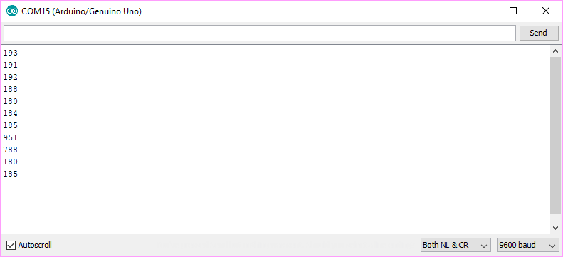
To debug this, I used this Arduino Sketch
              #include < Wire.h >

                int check=0;

                void setup() {
                  Wire.begin();        // join i2c bus (address optional for master)
                  Serial.begin(9600);  // start serial for output
                }

                void loop() {
                  Wire.requestFrom(8, 2);    // request 2 bytes from slave device #8

                  while (Wire.available()&&check < 2) { // slave may send less than requested
                    int c = Wire.read(); // receive a byte as character
                    check++;
                    int d = Wire.read();
                    check++;
                    // print the character
                    int number = d | c << 8;
                    Serial.println(number);
                  }
                  check=0;
                  delay(500);
                }
In the while loop it waits (check < 2) for two reads from the I2C bus, then it recreate the int, with bitwise operation: an OR operation between the highest part of the int (the most significant bit) shifted by 8 bits with the lowest part.
Then, I moved the code (migrating from Wire.h to TinyWireM.h) in the AtTiny44, by attaching the photoresistor board with the I2C.
Few differences: the Wire.receive() becomes TinyWireM.read(), and you need to set high pull up on the line (as said above).
                #include < TinyWireM.h >
                #include < USI_TWI_Master.h >

                #include < SoftwareSerial.h >
                SoftwareSerial mySerial(0, 1); // RX, TX

                int adc = 2;
                int check=0;

                // the setup function runs once when you press reset or power the board
                void setup() {
                  pinMode(1, OUTPUT);
                  pinMode(0, INPUT);
                  // 4 6
                  pinMode(4,INPUT_PULLUP);
                  pinMode(6,INPUT_PULLUP);
                  pinMode(7, OUTPUT);
                  pinMode(adc, INPUT);
                  mySerial.begin(9600);
                  TinyWireM.begin();        // join i2c bus (address optional for master)
                  while (!mySerial) {
                    ;
                  }
                  mySerial.println("Serial comm started");
                  digitalWrite(7, HIGH);
                  delay(1000);
                  digitalWrite(7, LOW);
                }

                // the loop function runs over and over again forever
                void loop() {
                  mySerial.println((int)analogRead(adc));
                  TinyWireM.requestFrom(8, 2);    // request 2 bytes from slave device #8
                  while (TinyWireM.available()&&check < 2) { // slave may send less than requested
                    digitalWrite(7, HIGH);
                    int c = TinyWireM.receive(); // receive a byte as character
                    check++;
                    int d = TinyWireM.receive();
                    check++;
                    int number = d | c << 8;
                    mySerial.println(number);
                  }
                  check=0;
                  delay(500);
                }
This code also print using softwareSerial the value read from the thermistor.
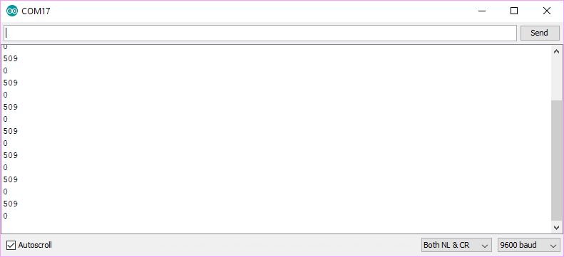
But, unfortunately it is not working as it should.
I then debugged the communication, by scaling down software, because I did not find any solution to this problem.
I implemented a communication, then, where the master device every second asks for a byte to the slave.
The slave then send “1” and, on the one received, the LED on the master turns on.
Code of the master:
                #include < TinyWireM.h >
                #include < USI_TWI_Master.h >
                #include < SoftwareSerial.h >
                // 1 , 0
                SoftwareSerial mySerial(0, 1); // RX, TX

                int adc = 2;
                int rec;

                // the setup function runs once when you press reset or power the board
                void setup() {
                  pinMode(1, OUTPUT);
                  pinMode(0, INPUT);
                  pinMode(4, INPUT_PULLUP);
                  pinMode(6, INPUT_PULLUP);
                  pinMode(7, OUTPUT);
                  TinyWireM.begin();        // join i2c bus (address optional for master)
                  digitalWrite(7, HIGH);
                  delay(1000);
                  digitalWrite(7, LOW);
                  delay(100);
                }

                // the loop function runs over and over again forever
                void loop() {
                  TinyWireM.requestFrom(8, 1);    // request 1 bytes from slave device #8
                  while (TinyWireM.available()) {
                    rec = TinyWireM.read();
                    if (rec == 1) digitalWrite(7, HIGH);
                  }
                  delay(1000);
                  digitalWrite(7, LOW);
                }
Slave code:
                // Code for the ATtiny85
                #define I2C_SLAVE_ADDRESS 0x8 // Address of the slave

                #include < TinyWireS.h >

                void setup() {
                  TinyWireS.begin(I2C_SLAVE_ADDRESS); // join i2c network
                  TinyWireS.onRequest(requestEvent);
                  pinMode(4,OUTPUT);
                  digitalWrite(4,HIGH);
                }

                void loop() {
                  // This needs to be here
                  TinyWireS_stop_check();
                }

                // Gets called when the ATtiny receives an i2c request
                void requestEvent() {
                  TinyWireS.send(1);
                }
Video of the code:
Networking from Nicola Giannelli on Vimeo.
Source codes - .zip