Computer-aided Design (CAD)
1. Week assignment
Model (raster, vector, 2D, 3D, render, animate, simulate, ...) a possible final project, and post it on your class page.
2. Development Environment
I used Corel Draw X7 and SolidWorks 2016 on a Windows 10 environment.
3. CAD
CAD (Computer-aided design) softwares are used to speed up design process, especially 2D and 3D designs.
3.1 CorelDraw
CorelDraw is a vector graphic editor software. I decided to use this software because I used this years ago, but i never properly learned to use it.
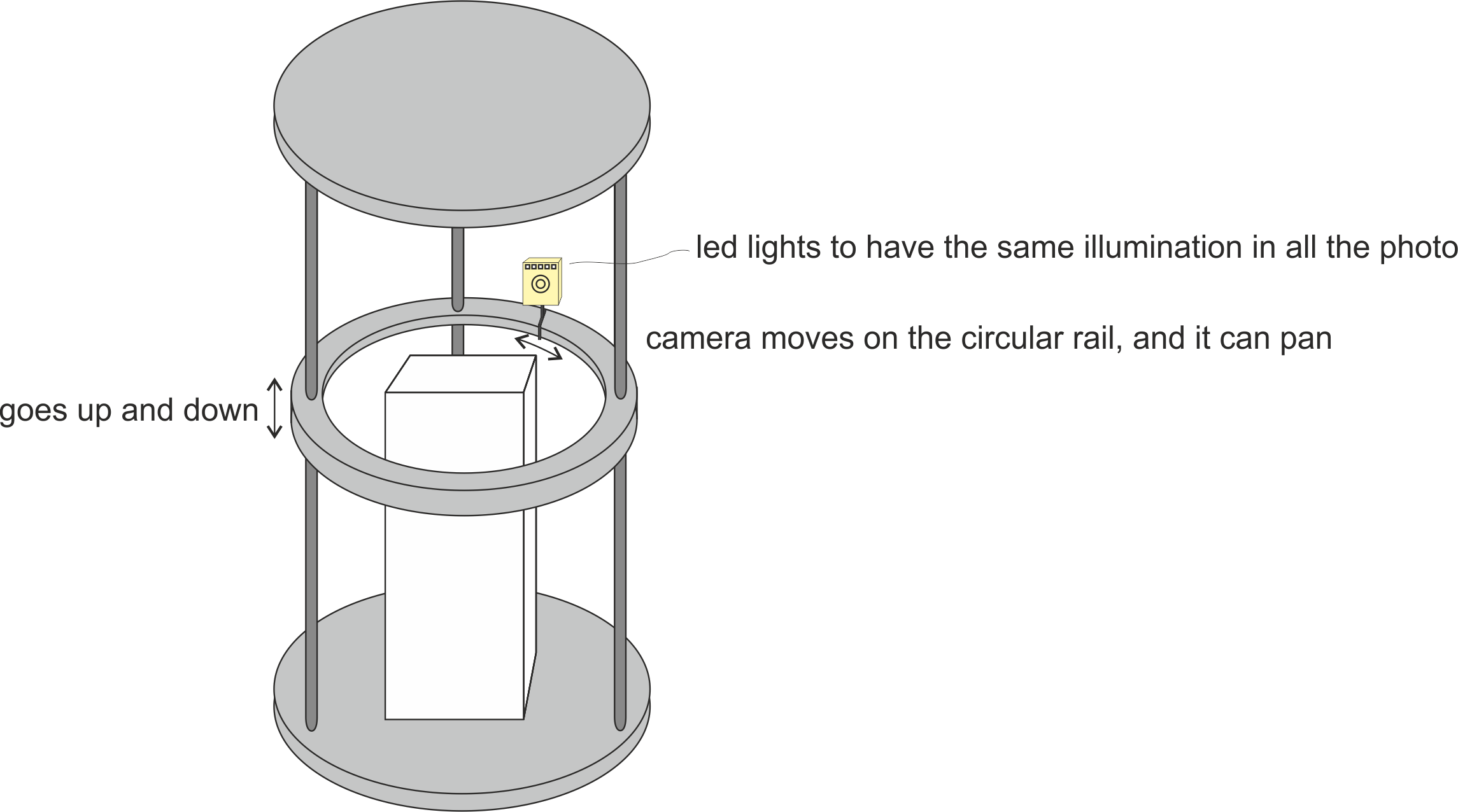
This is the final project draft I made.
In this model is all vectorial, drawn “by hand”, using the tools integrated in the program (circles, ellipses, squares…): the problem is that this approach to 3D modelling is problematic, being the program not designed for this (as far as I know):
The problems I had were about layers, prospective and the supports: i did not manage to make holes in the camera rail.
I then decided to move on SolidWorks.
3.2 SolidWorks
SolidWorks, unlike CorelDraw, is for 3D modelling. I had to learn this from scratch, because I’ve never used this program.
At first I followed tutorial integrated on program, which gave me this part.
Then I tried to model the draft for the final project. This is the final result:
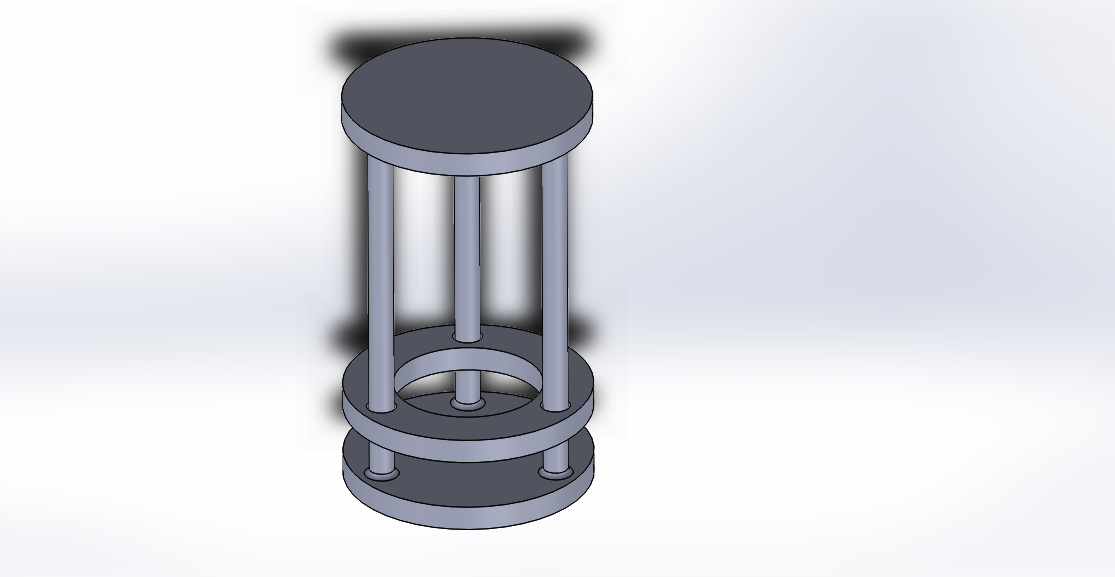
I made a circle on the origin and extruded it to get the base.
Then I extruded one “arm”, used a fillet on it to don’t leave a sharp edge, as I did not liked it.
Using circular pattern (by choosing the fillet and the arm, with the center of the base as rotating point) I repeated with auto spacing to have two more arms.
On top of the 3 arms, I extruded another circle, to get the upper base.
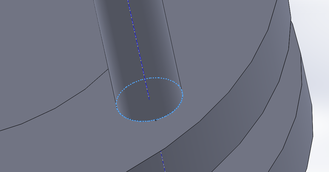
To make the rail, i made a round extrusion with an offset from the lower base, then, by using offset entities and extruded cut, I managed to get the holes for the arms and the hollow inside.
This approach to 3D modelling is more pain-free that the one I tried with CorelDraw.
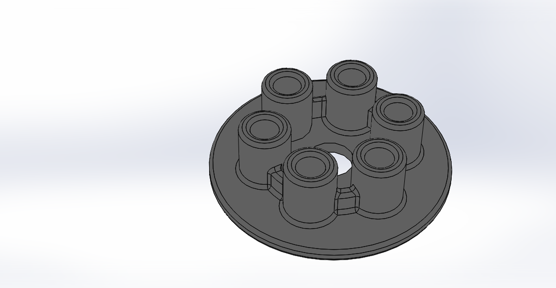
I also here had problem with supports holes: the first try i made gave me a unsatisfying result:
As I am not familiar with the program, i had to start from blank file and re-do this.
The workflow of Solidworks was completely new for me; that’s what I learned:
- You choose a plane (it can be X,Y,Z, or any surface in the model)
- You place here a sketch; you draw something (figures, letters,...)
- You choose a feature for this sketch: it can be an extrusion, a cut (only if you are on a surface, clearly)
- Combining all of the above you make your model (indeed there are more advanced features I do not know)
After doing this try, a colleague told me about assemblies: you do more parts, and you combine them; I could have made a part for the base, one single part for the rails and a part for the circle guide.
5. Files
First projectThe draft made with CorelDraw - .cdr - .ai
SolidWorks tutorial - .sltptr
SolidWorks first try, with wrong holes - .sltptr
SolidWorks second try - .sltptr
Update
It's possible to find more work about this week on the final project page in the related development section