Final Project
1. Description
My final project will be an IOT cube pairable with a smartphone/PC, used as a music controller.
Based on gyroscope movements and native applications API, you can control music you are reproducing: you can change the song you are listening to by rotating it, you can shuffle the music by shaking it.
It’s possible to use it as a volume controller, like a potentiometer: by rotating it with one side laying on the desk, you can increase or decrease music volume.
It will have an infrared sensor to play/stop music by swiping the hand over it.
It will have also programmable LEDs light, and it could read the temperature too.
This project is aimed at developers, who can use it as a starting point to develop their own uses for the CUBE, other than the musical one.
2. Concept
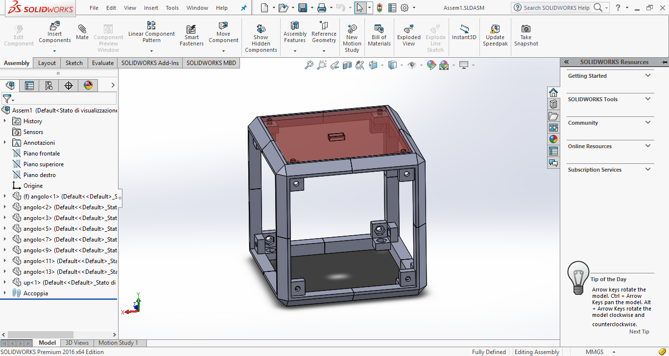
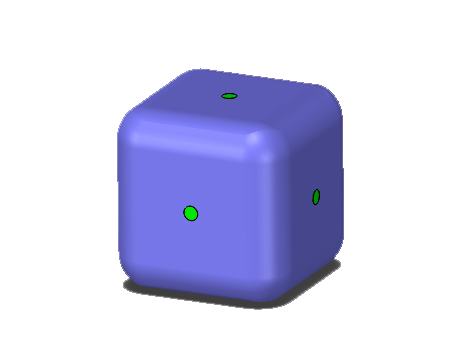 Solidworks rendering
The CUBE, as the name says, it’s a IOT device based on an Arduino 101, with the shape of a cube.
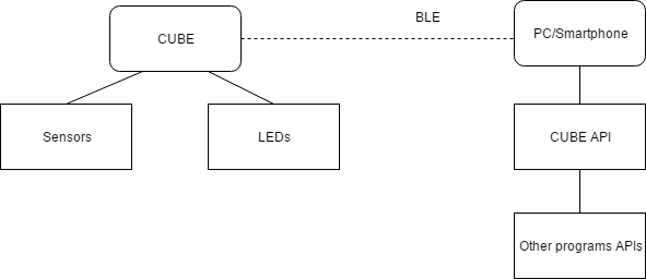
Main features:
- BLE enabled
- Battery powered
- 9-Axis gyroscope
- Distance measure
- 4 LEDs acting as output/information
Functions:
- Able to recognize rotations (clockwise and counterclockwise only): you can assign a function to the face or to the rotation event
- Able to recognize swipes of the hand
- Able to recognize the heading of the cube: you can get the angle of the CUBE
3. The technology
3.1 Arduino 101
Arduino 101 & Genuino 101 combine the ease-of-use of the classic Arduino boards with the latest technologies. The board recognises gestures, and features a six-axis accelerometer and gyroscope.
3.2 The system
4. Development
4.1 Designing process
Involved Fab Academy process: CAD, 3D printing, laser cutting, vinyl cutting4.1.2 First design
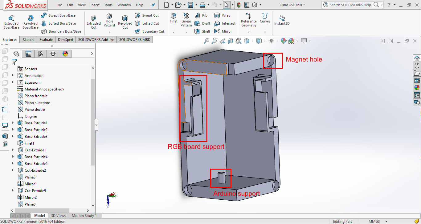
At first I decided to design a shell that could have been totally 3D printable.
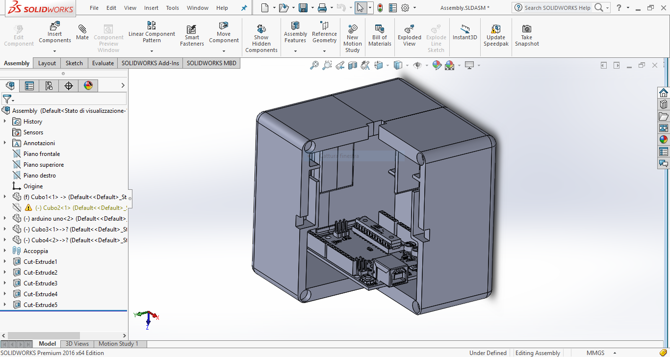
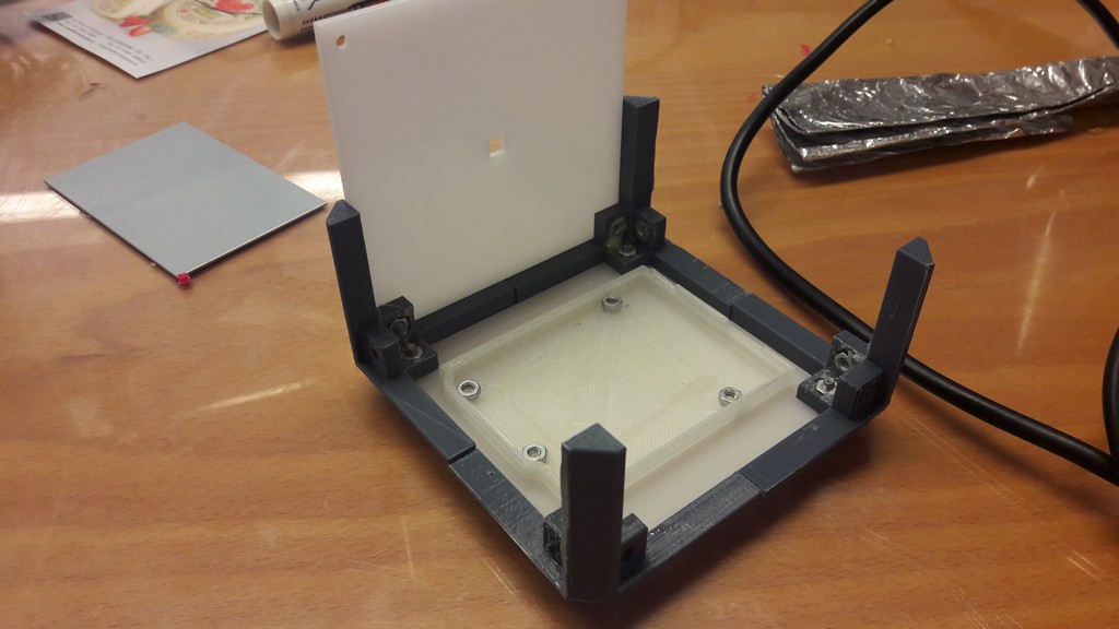
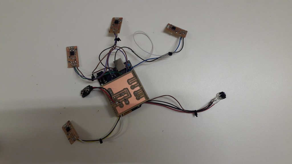
Final assembly
The idea was to split the cube in 4 parts, and using magnets to close it, with supports for the RGB board I developed (more on this later), supports for the Arduino and the battery, and in the upper face (as you can see from the photo above) a slot for putting the IR sensor.
In two of the the four pieces, there is a slot where the Arduino fits in.
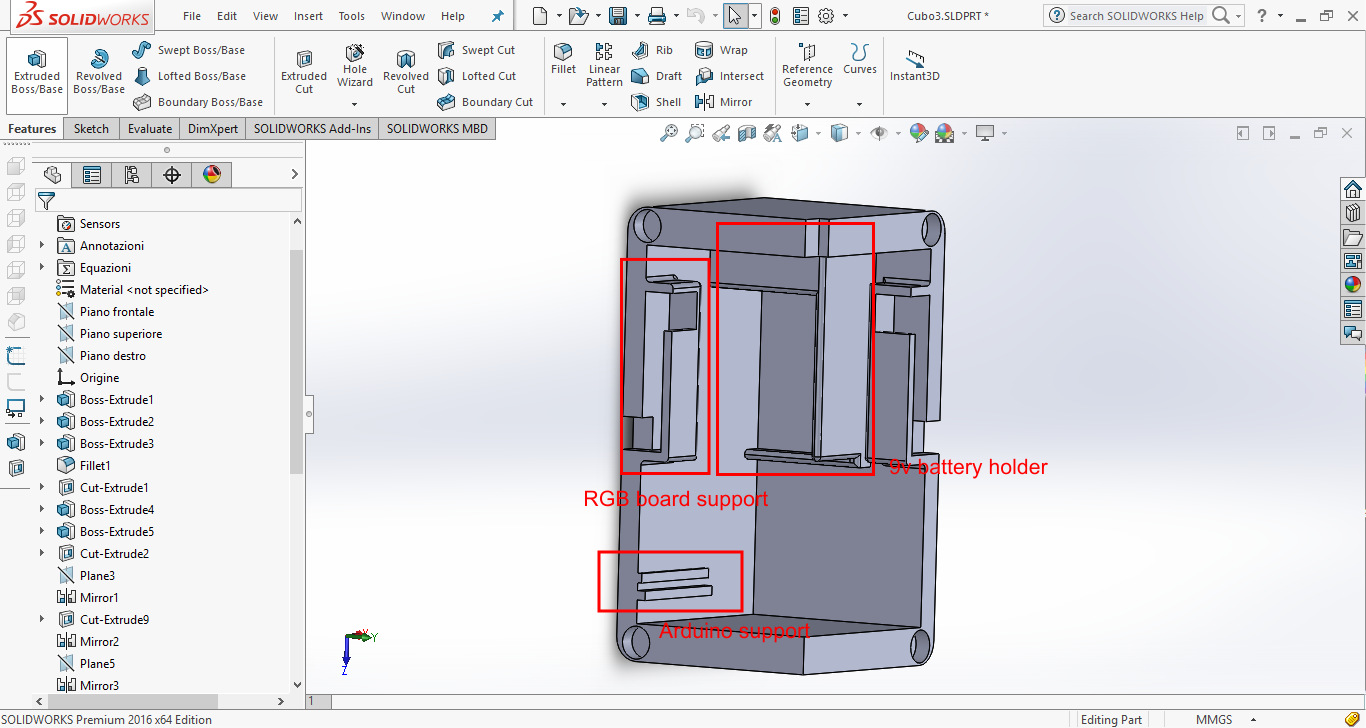
While in the other two there are screw supports: the idea is to screw the Arduino, then close half cube and then using magnets close everything.
And here’s a photo of a 3D printed part of the cube (it’s possible to see the closing magnets):
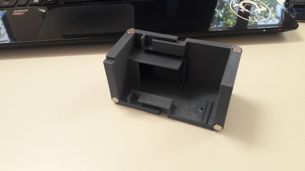
After printing it I decided to change design; a print of all the cube would take 15 hours (with 10% infill and low quality settings from CURA software): being so time consuming, a little error in design would take me days to fix.
4.1.2 Second design
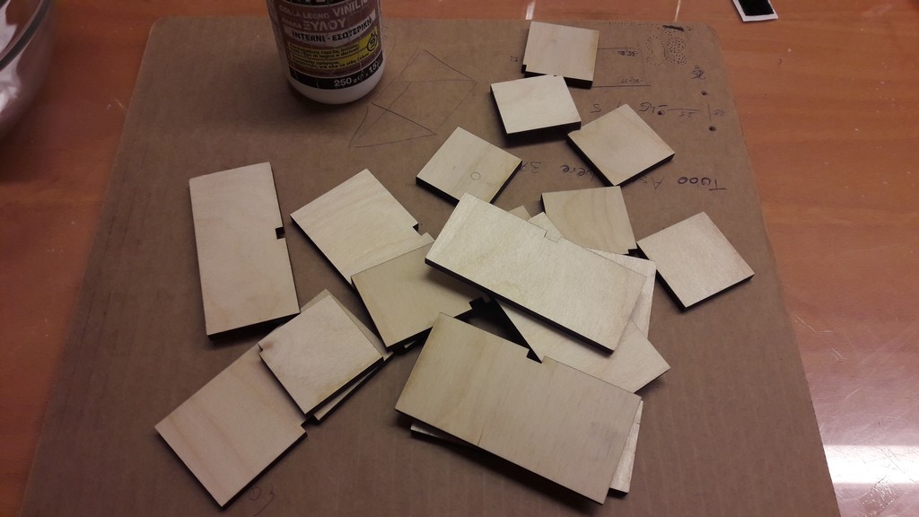
For the second design I decided to laser cut the faces from wood (birch wood).
I took off the fillets from Solidworks design files, and exported the faces to Illustrator to laser it with the lasercut we have in lab, the used glue wood for building them up.
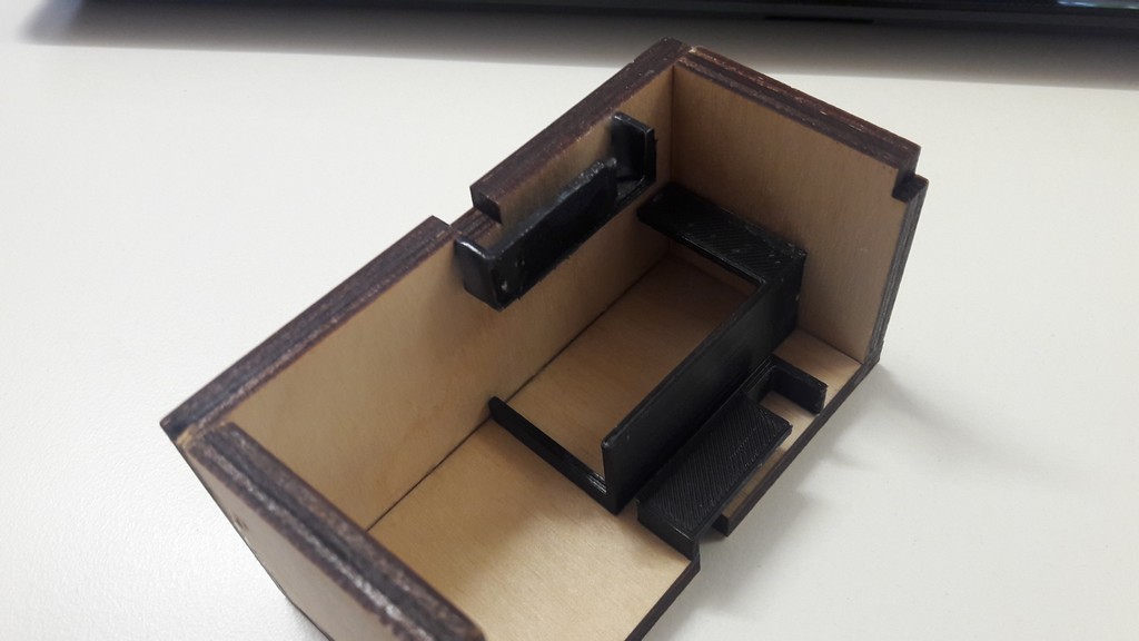
Then I redesigned the supports for boards, Arduino and battery.
The problem with this design is the closing: I wanted to use the same method I used in the initial design, the magnets.
I tried to drill in the side of the wood (along the cut) enough room to fit the magnets (the wood I used is 6.25mm thickness, while the magnets have 7mm diameters).
The wood, clearly, got destroyed and the glues I tried soaked the wood.
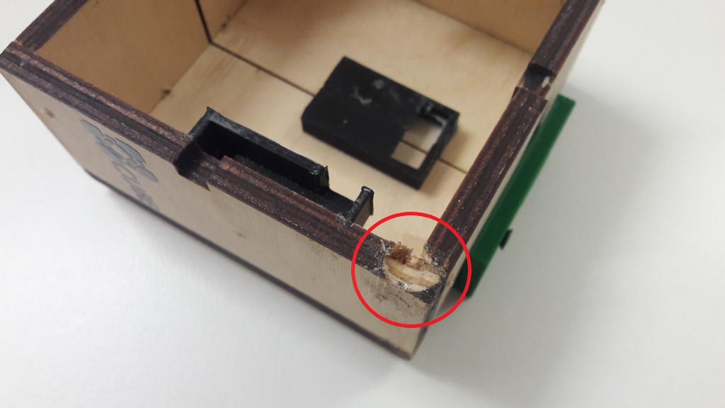
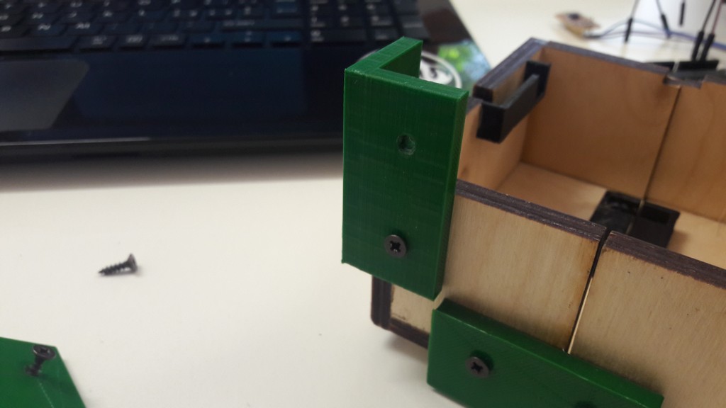
So I had to design external closings, using wood screws: a solution that is very uncomfortable to build (and to see too).
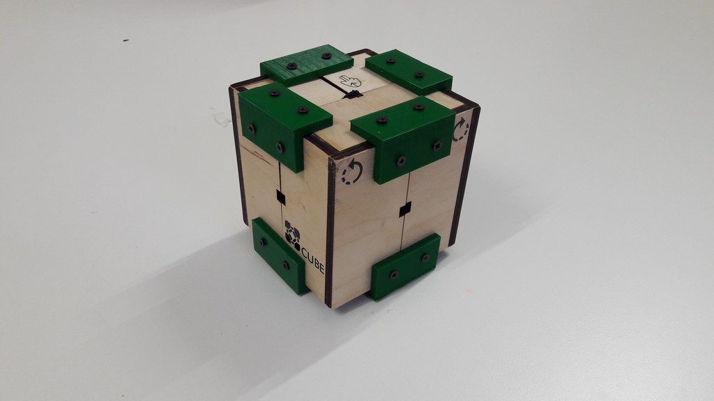
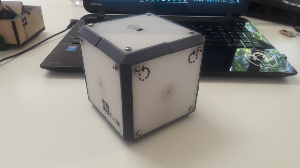
At this stage I also designed stickers to indicate where to swipe and in which way you can rotate the cube (the cube is not recognizing all rotations, more on this later).

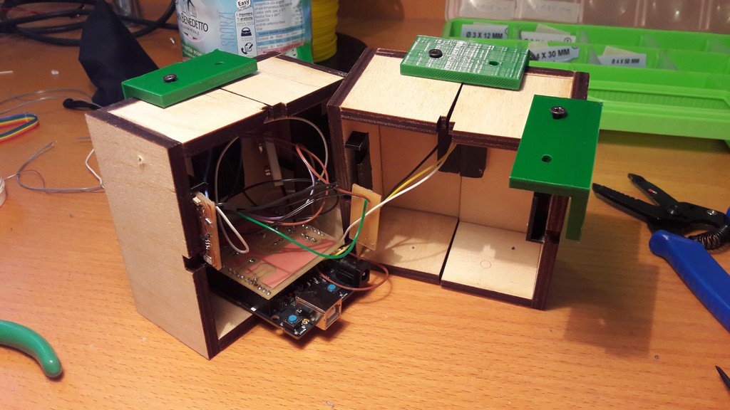
The assembled work:
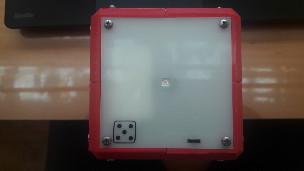
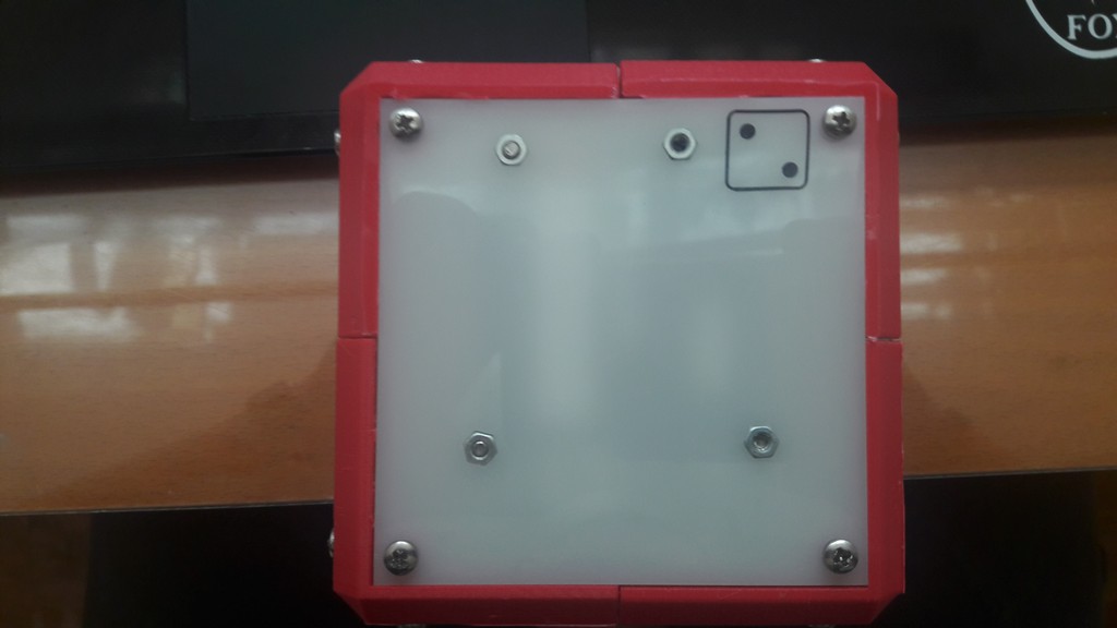
4.1.3 Final Design
Being not satisfied by the results I got I designed a different closing method and assembly system.
This final design features eight 3D printed “corners”, where it’s possible to put 3 nuts (each one), and the faces are lasered from 3mm white plexiglass.
Then, from the outside is possible to screw the faces, to get them close.
The Arduino has a 3D printed base with 4 nuts, glued to the lower face of the cube.
The electronic (LEDs and IR) is glued to the respectives holes.
The assembly process is much more simple: the Arduino is screwed in its support, the faces containing 3 LEDS and the IR are screwed to the base, so that only the face towards you needs to be closed.
At this stage you connect the breakout board to the arduino, and then you can close all the cube.
In this last design I left space for a ON/OFF mechanism, in the back face.
Off
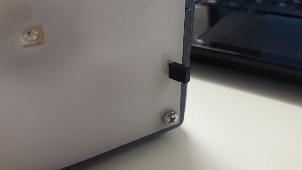
On
I applied the same stickers as the second design.
4.1.4 Design files - .zip
4.2 Electronics
Involved Fab Academy process: electronic design, electronic production4.2.1 LED board
I decided to implement a RGB LED controller, to save up space in the pinout of the Arduino (in this way I’m able to control 3 LEDs with only one digital wire), saving up to 8 pins.
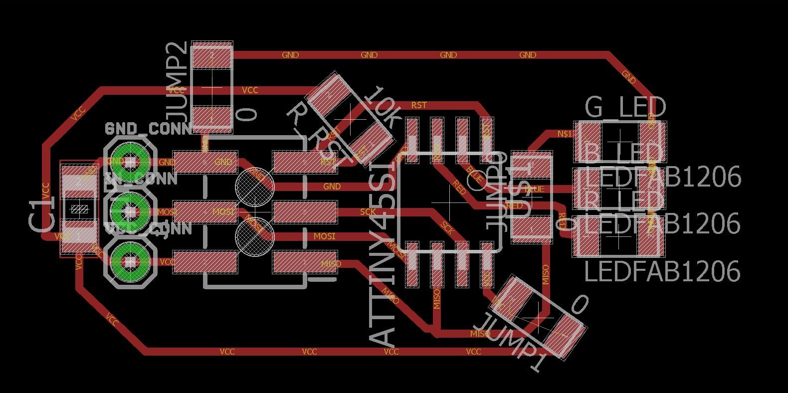
Component overview:
- AtTiny45V: the microcontroller
- 1 uF capacitor: the get rid of ripples in power supply
- ISP connector: for programming the board
- Holes for signal, supply, GND: the ISP is going to be desoldered after the programming to save space; these holes are for the wires to be soldered in the breakout
- 10 k resistor: used as pull-up for reset pin
- 0 resistor: used as jumpers
- LEDs: a red, green, and blue led
I had to use jumper to keep the board small: the initial idea was to use the RST pin on the AtTiny45 as output, so I could avoid using in addition to the jumpers the 10k resistor.
But after documenting myself I found that you can use the RST pin as input/output, by changing the fuses, but you can program it only one time, unless you use an high voltage (12V) programmer instead of the ISP, but unfortunately we do not have this kind of programmer in lab.
4.2.2 IR distance measurement and breakout board
Having worked before with IR distance measuring, I used this simple circuit:
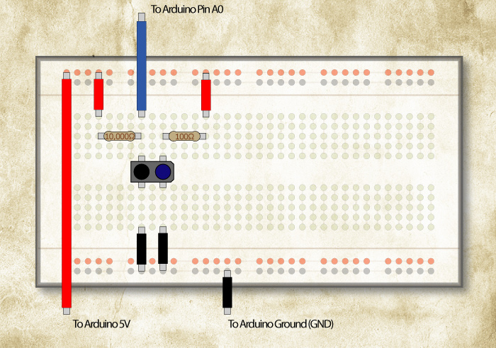
We have the IR emitter (in blue) that has a 100 ohm resistance in series to limit the current (the IR emitter is a diode, so too much current can burn it) and the IR receiver (in black) with a voltage divider that use a 10 kilo resistor.
The IR receiver is a photoresistor sensible to IR waves: it changes its value based on the IR light, where the IR light is provided by the emitter; an object in front of emitter changes the receiver resistance value (by reflecting the IR light), and therefore it changes the value read by the Arduino ADC.
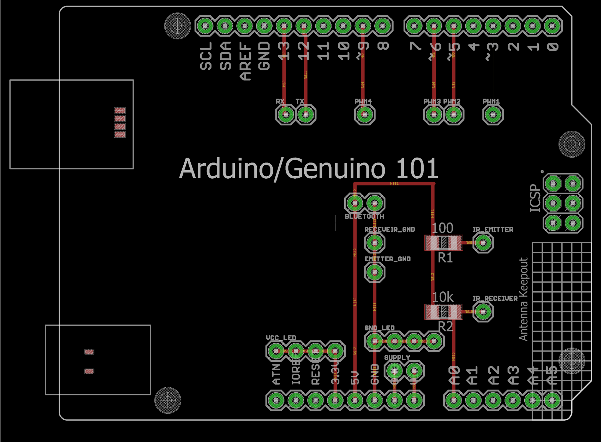
In the breakout I exposed VCC and GND for LEDs, the circuit for the IR emitter/receiver, the control lines for the LEDs board, and some extra pads for using an external bluetooth module (in case of necessity, i did not need it).
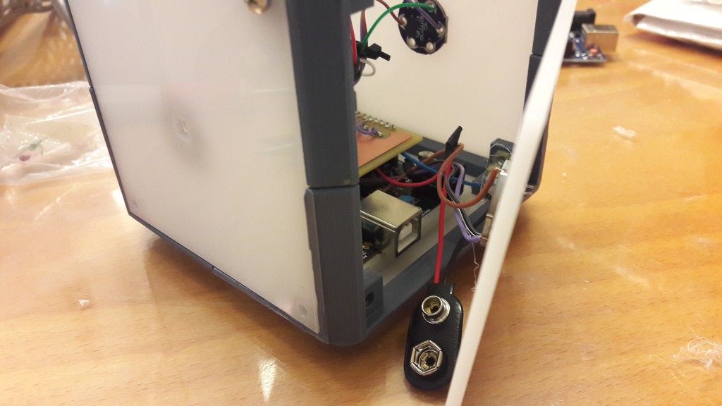
Also I exposed the VIN and GND pins for the external power supply: I there attached a 9V battery.
I then used a 2-pin male header to interrupt the ground line from the battery, and a jumper /the one you found in the old ATA hard drives) as switch: where the jumper is placed in the header, the CUBE is powered on.
In the last design of the CUBE, i decided to use Neopixel LEDs, instead of the board I designed, to have more control on color and brightness of lights.
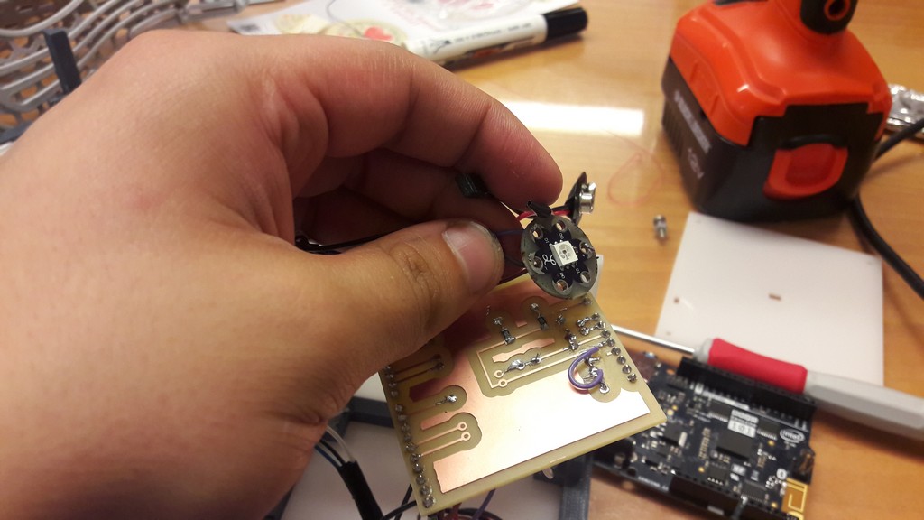
I had to jumper power supply: my boards did run at 3.3 Volts, the Neopixels run a 5 Volts
4.2.3 Files - .zip
4.3 Embedded programming and network communications
Involved Fab Academy process: embedded programming, networking4.3.1 The RGB board
Code:
            #define blue 1
            #define red 3
            #define green 4
            const int error=30;
            int value[8];
            int analog;

            void setup() {
              // put your setup code here, to run once:
              pinMode(1,OUTPUT); //BLUE
              pinMode(3,OUTPUT); //RED
              pinMode(4,OUTPUT); //GREEN
              pinMode(0,INPUT); //INPUT PWM
              value[0]=9;
              value[1]=248;
              value[2]=489;
              value[3]=722;
              value[4]=962;
              value[5]=1196;
              value[6]=1442;
              value[7]=1682;
            }

            void loop() {
              analog=pulseIn(0,HIGH);
              // 0 0 0
              if(analog==0){
                digitalWrite(red,LOW);
                digitalWrite(green,LOW);
                digitalWrite(blue,LOW);
              }

              // 0 0 1
              if(analog>=value[1]-error&&analog<=value[1]+error){
                digitalWrite(red,LOW);
                digitalWrite(green,LOW);
                digitalWrite(blue,HIGH);
              }

              // 0 1 0
              if(analog>=value[2]-error&&analog<=value[2]+error){
                digitalWrite(red,LOW);
                digitalWrite(green,HIGH);
                digitalWrite(blue,LOW);
              }

              // 0 1 1
              if(analog>=value[3]-error&&analog<=value[3]+error){
                digitalWrite(red,LOW);
                digitalWrite(green,HIGH);
                digitalWrite(blue,HIGH);
              }

              // 1 0 0
              if(analog>=value[4]-error&&analog<=value[4]+error){
                digitalWrite(red,HIGH);
                digitalWrite(green,LOW);
                digitalWrite(blue,LOW);
              }

              // 1 0 1
              if(analog>=value[5]-error&&analog<=value[5]+error){
                digitalWrite(red,HIGH);
                digitalWrite(green,LOW);
                digitalWrite(blue,HIGH);
              }

              // 1 1 0
              if(analog>=value[6]-error&&analog<=value[6]+error){
                digitalWrite(red,HIGH);
                digitalWrite(green,HIGH);
                digitalWrite(blue,LOW);
              }

              // 1 1 1
              if(analog>=value[7]-error&&analog<=value[7]+error){
                digitalWrite(red,HIGH);
                digitalWrite(green,HIGH);
                digitalWrite(blue,HIGH);
              }
              delay(10);
            }
As said above, I needed a way to control LEDs using just one line. I decide to implement a PWM protocol.
On the RGB board is running a sketch that control in every loop the value of the PWM on the pin 0, and accordingly to its value it lights up the LEDs.
It uses the pulseIn() function.
This function counts the number of HIGH or LOW edges on the pin, so I get a different values for different PWM values sent by the Arduino.
The downside is that this is not so precise, but this application does not require perfect timing (I assume LEDs will not be turned ON/OFF every millisecond), as the pulseIn() approximate the value, because the time in which it counts the edges is so little.
At every LED is assigned a value (1/0, low or high), and for 3 LEDs i have 16 combinations: at every combination is assigned a PWM value and a pulseIn() value.
As said above I introduced an error, because for the same PWM i do not get the same number of pulses counted: adding an error let me get the right value because the pulses being counted don’t get too much far for the nominal value (just like a normal distribution).
Here there are the values (to turn every led off simply use digitalWrite(LOW);):
| RED | GREEN | BLUE | PWM | pulseIn (# of high edges) | Range |
| 0 | 0 | 0 | 1 | 9 | 0 - 39 |
| 0 | 0 | 1 | 31 | 248 | 218 - 278 |
| 0 | 1 | 0 | 61 | 489 | 459 - 519 |
| 0 | 1 | 1 | 91 | 722 | 692 - 752 |
| 1 | 0 | 0 | 121 | 962 | 932 - 992 |
| 1 | 0 | 1 | 151 | 1196 | 1166 - 1226 |
| 1 | 1 | 0 | 181 | 1442 | 1412 - 1472 |
| 1 | 1 | 1 | 211 | 1682 | 1652 - 1712 |
In example, writing a PWM of 151 it will lights on the blue and red LEDs, while the value read by the pulseIn() function will be between 1166 and 1226, being the nominal value 1196 (the error I used is 30).
As you can see, if you want to manage more combinations it can be difficult due to this error.
Example with simple code and video:
            void setup() {
              pinMode(3,OUTPUT);
            }

            void loop() {
              analogWrite(3,1);
              delay(1000);
              analogWrite(3,31);
              delay(1000);
              analogWrite(3,61);
              delay(1000);
              analogWrite(3,91);
              delay(1000);
              analogWrite(3,121);
              delay(1000);
              analogWrite(3,151);
              delay(1000);
              analogWrite(3,181);
              delay(1000);
              analogWrite(3,211);
              delay(1000);
            }
Final - RGB Protocol from Nicola Giannelli on Vimeo.
4.3.2 The Arduino sketch (first version)
#include "CurieIMU.h"
#include
#include
int lastOrientation = - 1; // previous orientation (for comparison)
unsigned long previousMillis = 0;
const long interval = 500;
int ledState = LOW;
int side, oldSide;
char mode='0';
// 0 = standby
// 1 = rotation
// 2 = swipe
// 3 = potentiometer
char control='0';
int rotation=0;
// 1 right
// 2 left
// 0 wait
int swipe=0;
// 1 swipe
// 0 wait
// matrix using to calculate the cube side
float matrix[6][3] ={
{-1, 0, 0},
{0, -1, 0},
{0, 0, -1},
{1, 0, 0},
{0, 1, 0},
{0, 0, 1},
};
//variables to store the IR values
int oldDistance, distance;
//defining the filter for the potentiometer mode
Madgwick filter;
unsigned long microsPerReading, microsPrevious;
float accelScale, gyroScale;
float defaultAccRate;
// the built in LED
const int ledPin = LED_BUILTIN;
// aux variables
float offset;
bool check=false;
//starting the BLE protocl
BLEPeripheral blePeripheral;
//------------------------------------------------------------------------ BLE SERVICES
BLEService modeService("988dbab9-a657-45fe-80ef-9f9bed761947");
BLEService rotationService("988dbab9-a657-45fe-80ef-9f9bed761948");
BLEService ledService("988dbab9-a657-45fe-80ef-9f9bed761949");
BLEService swipeService("988dbab9-a657-45fe-80ef-9f9bed761950");
BLEService potService("988dbab9-a657-45fe-80ef-9f9bed761951");
//------------------------------------------------------------------------ BLE CHARACTERISTICS
BLEUnsignedCharCharacteristic rotationChar("06abf104-c81d-4d93-bce5-bc6b38188ba5", BLERead | BLEWrite | BLENotify);
BLECharCharacteristic switchChar("06abf104-c81d-4d93-bce5-bc6b38188ba4", BLERead | BLEWrite);
BLECharacteristic ledChar("06abf104-c81d-4d93-bce5-bc6b38188ba3", BLERead | BLEWrite, 4);
BLEUnsignedCharCharacteristic swipeChar("06abf104-c81d-4d93-bce5-bc6b38188ba2", BLERead | BLEWrite | BLENotify);
BLECharCharacteristic potChar("06abf104-c81d-4d93-bce5-bc6b38188ba1", BLERead | BLENotify);
//------------------------------------------------------------------------ LED CONTROL
char inData[4];
void rxCharacteristicWritten(BLECentral& central, BLECharacteristic& characteristic) {
if (characteristic.value()) { //check if there is value
if((char)characteristic.value()[0]=='3'){
// 0 0 0
if((char)characteristic.value()[1]=='0'&&(char)characteristic.value()[2]=='0'&&(char)characteristic.value()[3]=='0'){
analogWrite(3,1);
}
// 0 0 1
if((char)characteristic.value()[1]=='0'&&(char)characteristic.value()[2]=='0'&&(char)characteristic.value()[3]=='1'){
analogWrite(3,31);
}
// 0 1 0
if((char)characteristic.value()[1]=='0'&&(char)characteristic.value()[2]=='1'&&(char)characteristic.value()[3]=='0'){
analogWrite(3,61);
}
// 0 1 1
if((char)characteristic.value()[1]=='0'&&(char)characteristic.value()[2]=='1'&&(char)characteristic.value()[3]=='1'){
analogWrite(3,91);
}
// 1 0 0
if((char)characteristic.value()[1]=='1'&&(char)characteristic.value()[2]=='0'&&(char)characteristic.value()[3]=='0'){
analogWrite(3,121);
}
// 1 0 1
if((char)characteristic.value()[1]=='1'&&(char)characteristic.value()[2]=='0'&&(char)characteristic.value()[3]=='1'){
analogWrite(3,151);
}
// 1 1 0
if((char)characteristic.value()[1]=='1'&&(char)characteristic.value()[2]=='1'&&(char)characteristic.value()[3]=='0'){
analogWrite(3,181);
}
// 1 1 1
if((char)characteristic.value()[1]=='1'&&(char)characteristic.value()[2]=='1'&&(char)characteristic.value()[3]=='1'){
analogWrite(3,211);
}
}
if((char)characteristic.value()[0]=='5'){
// 0 0 0
if((char)characteristic.value()[1]=='0'&&(char)characteristic.value()[2]=='0'&&(char)characteristic.value()[3]=='0'){
analogWrite(5,1);
}
// 0 0 1
if((char)characteristic.value()[1]=='0'&&(char)characteristic.value()[2]=='0'&&(char)characteristic.value()[3]=='1'){
analogWrite(5,31);
}
// 0 1 0
if((char)characteristic.value()[1]=='0'&&(char)characteristic.value()[2]=='1'&&(char)characteristic.value()[3]=='0'){
analogWrite(5,61);
}
// 0 1 1
if((char)characteristic.value()[1]=='0'&&(char)characteristic.value()[2]=='1'&&(char)characteristic.value()[3]=='1'){
analogWrite(5,91);
}
// 1 0 0
if((char)characteristic.value()[1]=='1'&&(char)characteristic.value()[2]=='0'&&(char)characteristic.value()[3]=='0'){
analogWrite(5,121);
}
// 1 0 1
if((char)characteristic.value()[1]=='1'&&(char)characteristic.value()[2]=='0'&&(char)characteristic.value()[3]=='1'){
analogWrite(5,151);
}
// 1 1 0
if((char)characteristic.value()[1]=='1'&&(char)characteristic.value()[2]=='1'&&(char)characteristic.value()[3]=='1'){
analogWrite(5,181);
}
// 1 1 1
if((char)characteristic.value()[1]=='0'&&(char)characteristic.value()[2]=='0'&&(char)characteristic.value()[3]=='0'){
analogWrite(5,211);
}
}
if((char)characteristic.value()[0]=='6'){
// 0 0 0
if((char)characteristic.value()[1]=='0'&&(char)characteristic.value()[2]=='0'&&(char)characteristic.value()[3]=='0'){
analogWrite(6,1);
}
// 0 0 1
if((char)characteristic.value()[1]=='0'&&(char)characteristic.value()[2]=='0'&&(char)characteristic.value()[3]=='1'){
analogWrite(6,31);
}
// 0 1 0
if((char)characteristic.value()[1]=='0'&&(char)characteristic.value()[2]=='1'&&(char)characteristic.value()[3]=='0'){
analogWrite(6,61);
}
// 0 1 1
if((char)characteristic.value()[1]=='0'&&(char)characteristic.value()[2]=='1'&&(char)characteristic.value()[3]=='1'){
analogWrite(6,91);
}
// 1 0 0
if((char)characteristic.value()[1]=='1'&&(char)characteristic.value()[2]=='0'&&(char)characteristic.value()[3]=='0'){
analogWrite(6,121);
}
// 1 0 1
if((char)characteristic.value()[1]=='1'&&(char)characteristic.value()[2]=='0'&&(char)characteristic.value()[3]=='1'){
analogWrite(6,151);
}
// 1 1 0
if((char)characteristic.value()[1]=='1'&&(char)characteristic.value()[2]=='1'&&(char)characteristic.value()[3]=='1'){
analogWrite(6,181);
}
// 1 1 1
if((char)characteristic.value()[1]=='0'&&(char)characteristic.value()[2]=='0'&&(char)characteristic.value()[3]=='0'){
analogWrite(6,211);
}
}
if((char)characteristic.value()[0]=='9'){
// 0 0 0
if((char)characteristic.value()[1]==0&&(char)characteristic.value()[2]==0&&(char)characteristic.value()[3]==0){
analogWrite(9,1);
}
// 0 0 1
if((char)characteristic.value()[1]==0&&(char)characteristic.value()[2]==0&&(char)characteristic.value()[3]=='1'){
analogWrite(9,31);
}
// 0 1 0
if((char)characteristic.value()[1]==0&&(char)characteristic.value()[2]=='1'&&(char)characteristic.value()[3]==0){
analogWrite(9,61);
}
// 0 1 1
if((char)characteristic.value()[1]==0&&(char)characteristic.value()[2]=='1'&&(char)characteristic.value()[3]=='1'){
analogWrite(9,91);
}
// 1 0 0
if((char)characteristic.value()[1]=='1'&&(char)characteristic.value()[2]==0&&(char)characteristic.value()[3]==0){
analogWrite(9,121);
}
// 1 0 1
if((char)characteristic.value()[1]=='1'&&(char)characteristic.value()[2]==0&&(char)characteristic.value()[3]=='1'){
analogWrite(9,151);
}
// 1 1 0
if((char)characteristic.value()[1]=='1'&&(char)characteristic.value()[2]=='1'&&(char)characteristic.value()[3]=='0'){
analogWrite(9,181);
}
// 1 1 1
if((char)characteristic.value()[1]=='1'&&(char)characteristic.value()[2]=='1'&&(char)characteristic.value()[3]=='1'){
analogWrite(9,211);
}
}
}
}
//------------------------------------------------------------------------ BLE EVENT HANDLERS
void switchMode(BLECentral& central, BLECharacteristic& characteristic) {
// central wrote new value to characteristic
Serial.print("Characteristic event, written: ");
if (switchChar.value()==1) {
Serial.println("Rotation mode");
} else if(switchChar.value()==2) {
Serial.println("Swipe mode");
}
else if(switchChar.value()==3) {
Serial.println("Potentiometer mode");
}
}
void blePeripheralConnectHandler(BLECentral& central) {
// central connected event handler
Serial.print("Connected event, central: ");
Serial.println(central.address());
}
void blePeripheralDisconnectHandler(BLECentral& central) {
// central disconnected event handler
Serial.print("Disconnected event, central: ");
Serial.println(central.address());
}
//------------------------------------------------------------------------ BLE SETUP
void setup() {
//setting pin modes
pinMode(ledPin, OUTPUT);
pinMode(A0,INPUT);
pinMode(3,OUTPUT);
pinMode(5,OUTPUT);
pinMode(6,OUTPUT);
pinMode(9,OUTPUT);
Serial.begin(9600);
// initialize device
Serial.println("Initializing IMU device...");
CurieIMU.begin();
defaultAccRate=CurieIMU.getAccelerometerRate();
// Set the accelerometer range to 2G
CurieIMU.setAccelerometerRange(2);
CurieIMU.setGyroRate(25);
//the filter get initialized
filter.begin(25);
// Set the gyroscope range to 250 degrees/second
CurieIMU.setGyroRange(250);
microsPerReading = 1000000 / 25;
microsPrevious = micros();
// BLE
// set the local name peripheral advertises
blePeripheral.setLocalName("CUBE");
// set the UUID for the service this peripheral advertises
blePeripheral.setAdvertisedServiceUuid(modeService.uuid());
// add services and characteristics
blePeripheral.addAttribute(modeService);
blePeripheral.addAttribute(switchChar);
blePeripheral.addAttribute(rotationService);
blePeripheral.addAttribute(rotationChar);
blePeripheral.addAttribute(ledService);
blePeripheral.addAttribute(ledChar);
blePeripheral.addAttribute(swipeService);
blePeripheral.addAttribute(swipeChar);
blePeripheral.addAttribute(potService);
blePeripheral.addAttribute(potChar);
// assign event handlers for connected, disconnected to peripheral
blePeripheral.setEventHandler(BLEConnected, blePeripheralConnectHandler);
blePeripheral.setEventHandler(BLEDisconnected, blePeripheralDisconnectHandler);
// assign event handlers for characteristics
switchChar.setEventHandler(BLEWritten, switchMode);
ledChar.setEventHandler(BLEWritten, rxCharacteristicWritten);
// set an initial value for the characteristics
switchChar.setValue(0);
rotationChar.setValue(rotation);
swipeChar.setValue(swipe);
// advertise the services
blePeripheral.begin();
Serial.println(("Bluetooth device active, waiting for connections..."));
}
void loop() {
unsigned long currentMillis = millis();
if(switchChar.value()==0){ // STAND BY
}
if(switchChar.value()==1){ // ROTATION MODE
// read accelerometer:
CurieIMU.setAccelerometerRate(defaultAccRate);
float x = CurieIMU.readAccelerometer(X_AXIS);
float y = CurieIMU.readAccelerometer(Y_AXIS);
float z = CurieIMU.readAccelerometer(Z_AXIS);
oldSide=cubeSide(x,y,z);
side=cubeSide(CurieIMU.readAccelerometer(X_AXIS),CurieIMU.readAccelerometer(Y_AXIS),CurieIMU.readAccelerometer(Z_AXIS));
// if side has changed
if (side != oldSide) {
if(side==5){
//Serial.print(side);
//Serial.print(" ");
if(oldSide==4) {
//Serial.println("DX rotation");
rotationChar.setValue(2);
//analogWrite(3,121); used as led output in presentation video
}
if(oldSide==1){
//Serial.println("SX rotation");
rotationChar.setValue(1);
//analogWrite(3,121); used as led output in presentation video
}
}
if(side==1){
//Serial.print(side);
//Serial.print(" ");
if(oldSide==5){
//Serial.println("DX rotation");
rotationChar.setValue(2);
//analogWrite(3,121); as above
}
if(oldSide==2){
//Serial.println("SX rotation");
rotationChar.setValue(1);
//analogWrite(3,121);
}
}
if(side==4){
//Serial.print(side);
//Serial.print(" ");
if(oldSide==2) {
//Serial.println("DX rotation");
rotationChar.setValue(2);
//analogWrite(3,121);
}
if(oldSide==5) {
//Serial.println("SX rotation");
rotationChar.setValue(1);
//analogWrite(3,121);
}
}
if(side==2){
//Serial.print(side);
//Serial.print(" ");
if(oldSide==1) {
//Serial.println("DX rotation");
rotationChar.setValue(2);
//analogWrite(3,121);
}
if(oldSide==4){
//Serial.println("SX rotation");
rotationChar.setValue(1);
//analogWrite(3,121);
}
}
//Serial.println(side);
oldSide=side;
delay(1000); // wait before catching a new rotation
//analogWrite(3,1); // turn off the led
}
}
if(switchChar.value()==2){ // SWIPE MODE
oldDistance=analogRead(A0);
delay(500);
distance=analogRead(A0);
if(distance-oldDistance>100) {
Serial.println("SWIPE");
swipeChar.setValue(1);
//analogWrite(3,121); as above
delay(1000);
}
//analogWrite(3,1); // turn off the led
oldDistance=distance;
}
if(switchChar.value()==3){ // POTENTIOMETER MODE
CurieIMU.setAccelerometerRate(25);
int aix, aiy, aiz;
int gix, giy, giz;
float ax, ay, az;
float gx, gy, gz;
//float roll, pitch;
float heading;
unsigned long microsNow;
// check if it's time to read data and update the filter
microsNow = micros();
if (microsNow - microsPrevious >= microsPerReading) {
// read raw data from CurieIMU
CurieIMU.readMotionSensor(aix, aiy, aiz, gix, giy, giz);
// convert from raw data to gravity and degrees/second units
ax = convertRawAcceleration(aix);
ay = convertRawAcceleration(aiy);
az = convertRawAcceleration(aiz);
gx = convertRawGyro(gix);
gy = convertRawGyro(giy);
gz = convertRawGyro(giz);
// update the filter, which computes orientation
filter.updateIMU(gx, gy, gz, ax, ay, az);
// print the heading, pitch and roll
if(check==false){
CurieIMU.autoCalibrateGyroOffset();
CurieIMU.autoCalibrateAccelerometerOffset(X_AXIS, 0);
CurieIMU.autoCalibrateAccelerometerOffset(Y_AXIS, 0);
CurieIMU.autoCalibrateAccelerometerOffset(Z_AXIS, 1);
for(int i=0;i<10;i++){
offset+=filter.getYaw();
}
offset=offset/10;
check=true;
}
heading = filter.getYaw();
heading=heading-offset;
heading=round(heading);
Serial.println(heading);
potChar.setValue(heading);
delay(500);
// code used for lighting up the LED in presentation video
/*
if(heading>0){
analogWrite(3,121);
}
else{
analogWrite(3,1);
}
*/
// increment previous time, so we keep proper pace
microsPrevious = microsPrevious + microsPerReading;
}
}
//keep alive; turn off/on every second the built in led
if (currentMillis - previousMillis >= interval) {
previousMillis = currentMillis;
ledState=!ledState;
digitalWrite(ledPin, ledState);
}
}
//calculate the actual side of the cube, using dot products
int cubeSide(float Ax, float Ay, float Az){
float largest_dot = 0;
int closest_side = -1; // will return -1 in case of a zero A vector
for(int side = 0; side < 6; side++){
float dot = (matrix[side][0] * Ax) +(matrix[side][1] * Ay) +(matrix[side][2] * Az);
if(dot > largest_dot){
largest_dot = dot;
closest_side = side;
}
}
return closest_side;
}
// convert raw acceleration
float convertRawAcceleration(int aRaw) {
// since we are using 2G range
// -2g maps to a raw value of -32768
// +2g maps to a raw value of 32767
float a = (aRaw * 2.0) / 32768.0;
return a;
}
//convert raw gyro
float convertRawGyro(int gRaw) {
// since we are using 250 degrees/seconds range
// -250 maps to a raw value of -32768
// +250 maps to a raw value of 32767
float g = (gRaw * 250.0) / 32768.0;
return g;
}
This was the most difficult part of the final project.
I never used BLE, so I started by studying the protocol, and CurieBLE library used by Arduino 101 is poorly documented.
It is not like the standard bluetooth protocol (the one used by my colleagues, with the HC-05/06 modules).
The “old” bluetooth protocol is an emulated serial over bluetooth, so you can use it like a standard hardware serial.
The BLE stack works in a different way: it’s not a continuous flow of information, but it works like a bulletin board, or an RSS feed.
You define your own characteristic, that have services: at every services it’s assigned a value.
Then you “subscribe” to these services, and, depending on how are they defined, you can read (BLERead) or write (BLEWrite) the characteristic, or get notified (BLENotify) by the value changes (in my code, when you swipe or you rotate the cube the characteristic as soon as gets update it’s transmitted to the device connected).
Every characteristic and service has an UUID (Universal Unique IDentifier), used to discriminate between the services/characteristics, and an handler that is triggered on read/write of the service value.
I have 5 services with 5 characteristics:
- rotationChar, read/write/notify
This service keeps tracks of the rotation. When it’s 0 no rotation happened, 1 I’ve rotated the CUBE left, 2 I’ve rotated the CUBE right.
To use this service you subscribe to the characteristic, when a rotation happens you read either 1 or 2.
To catch another rotation it’s needed to write 0 on the service value.
Actually, I managed to recognize only left/right rotations
- switchChar, read/write
This service let you choose the mode you want to use the CUBE:
- 0: stand by
- 1: rotation mode
- 2: swipe recognition
- 3: potentiometer mode
- ledChar, read/write
This service let you control the RGB boards.
To use this you send a byte array of 4 elements, where the first elements is the PWM pin you wanna control (3,5,6 or 9) and the 3 followings are which LED should power on, based on the table reported above
i.e. sending 33313030 (3100) lights up the red LED on the board connected to PWM pin 3
- swipeChar, read/write/notify
This service keeps track of swipes
To use this service you subscribe to the characteristic, when a swipe happens you read 1. To catch another swipe it’s needed to write 0 on the service value.
- potChar, read/notify
This service notify the angle of the heading of the board. Simply enter the potentiometer mode, the code will use this starting position as 0 degree, and it will continue notify the angle.
The IMU (Inertia Mesaurement Unit) is a circuit which has an accelerometer and a gyroscope, by using the Madwigck filter (see in the references) you can get heading, pitch and roll of the board.
There is a little drifting due to the PID controlling the IMU, so, ad example in this application, I get an error of 2 degree every half an hour
I also use the IMU to get the face on which the board is lying.
In the method cubeSide by doing dot products with the matrix containing the normals of the cube faces, the smallest dot product gives you the face lying on the desk.
The logic behind the swipe is that when you swipe over the IR, clearly, the value read by the ADC goes down and then, after the hand has passed, it goes up again.
I decided to implement this recognition by reading the value, wait a half second and if the new value is lower by a value (in my case I decided 100) a swipe has happened.
This because the IR is sensible to ambient light, so same distance with different light (lamps turned on/off, morning/evening), gives me different values.
4.3.3 The Arduino sketch (second version)
In the second version of the cube I decided to use Neopixel LEDs.
Code:
#include "CurieIMU.h"
#include
#include
#include
#define LED1 3
#define LED2 5
#define LED3 6
#define LED4 9
Adafruit_NeoPixel pixel1 = Adafruit_NeoPixel(1, LED1, NEO_GRB + NEO_KHZ800);
Adafruit_NeoPixel pixel2 = Adafruit_NeoPixel(1, LED2, NEO_GRB + NEO_KHZ800);
Adafruit_NeoPixel pixel3 = Adafruit_NeoPixel(1, LED3, NEO_GRB + NEO_KHZ800);
Adafruit_NeoPixel pixel4 = Adafruit_NeoPixel(1, LED4, NEO_GRB + NEO_KHZ800);
int lastOrientation = - 1; // previous orientation (for comparison)
unsigned long previousMillis = 0;
const long interval = 500;
int ledState = LOW;
int side, oldSide;
char mode='0';
// 0 = standby
// 1 = rotation
// 2 = swipe
// 3 = potentiometer
char control='0';
int rotation=0;
// 1 right
// 2 left
// 0 wait
int swipe=0;
// 1 swipe
// 0 wait
float matrix[6][3] ={
{-1, 0, 0},
{0, -1, 0},
{0, 0, -1},
{1, 0, 0},
{0, 1, 0},
{0, 0, 1},
};
int oldDistance, distance;
Madgwick filter;
unsigned long microsPerReading, microsPrevious;
float accelScale, gyroScale;
float defaultAccRate;
const int ledPin = LED_BUILTIN;
float offset;
bool check=false;
BLEPeripheral blePeripheral;
//------------------------------------------------------------------------ BLE SERVICES
BLEService modeService("988dbab9-a657-45fe-80ef-9f9bed761947");
BLEService rotationService("988dbab9-a657-45fe-80ef-9f9bed761948");
BLEService ledService("988dbab9-a657-45fe-80ef-9f9bed761949");
BLEService swipeService("988dbab9-a657-45fe-80ef-9f9bed761950");
BLEService potService("988dbab9-a657-45fe-80ef-9f9bed761951");
//------------------------------------------------------------------------ BLE CHARACTERISTICS
BLEUnsignedCharCharacteristic rotationChar("06abf104-c81d-4d93-bce5-bc6b38188ba5", BLERead | BLEWrite | BLENotify);
BLECharCharacteristic switchChar("06abf104-c81d-4d93-bce5-bc6b38188ba4", BLERead | BLEWrite);
BLECharacteristic ledChar("06abf104-c81d-4d93-bce5-bc6b38188ba3", BLERead | BLEWrite, 16);
BLEUnsignedCharCharacteristic swipeChar("06abf104-c81d-4d93-bce5-bc6b38188ba2", BLERead | BLEWrite | BLENotify);
BLECharCharacteristic potChar("06abf104-c81d-4d93-bce5-bc6b38188ba1", BLERead | BLENotify);
//------------------------------------------------------------------------ TEST
void changeColor(char control[16]){
char _red[4], _green[4], _blue[4], _brightness[4], _white[4];
int red, green, blue, brightness, white, offset;
_red[3]='\0';
_green[3]='\0';
_blue[3]='\0';
_white[3]='\0';
_brightness[3]='\0';
offset=1;
for(int i=0;i<3;i++){
_red[i]=control[i+offset];
}
offset=4;
for(int i=0;i<3;i++){
_green[i]=control[i+offset];
}
offset=7;
for(int i=0;i<3;i++){
_blue[i]=control[i+offset];
}
offset=10;
for(int i=0;i<3;i++){
_white[i]=control[i+offset];
}
offset=13;
for(int i=0;i<3;i++){
_brightness[i]=control[i+offset];
}
red=atoi(_red);
green=atoi(_green);
blue=atoi(_blue);
white=atoi(_white);
brightness=atoi(_brightness);
if(control[0]=='3'){
pixel1.setPixelColor(0,red,green,blue,white);
pixel1.setBrightness(brightness);
pixel1.show();
}
if(control[0]=='5'){
pixel2.setPixelColor(0,red,green,blue,white);
pixel2.setBrightness(brightness);
pixel2.show();
}
if(control[0]=='6'){
pixel3.setPixelColor(0,red,green,blue,white);
pixel3.setBrightness(brightness);
pixel3.show();
}
if(control[0]=='9'){
pixel4.setPixelColor(0,red,green,blue,white);
pixel4.setBrightness(brightness);
pixel4.show();
}
}
void rxCharacteristicWritten(BLECentral& central, BLECharacteristic& characteristic) {
if (characteristic.value()) { //check if there is value
char control[17];
strncpy(control,(char *)characteristic.value(),16);
control[17]='\0';
Serial.println(control);
changeColor(control);
}
}
//------------------------------------------------------------------------ BLE EVENT HANDLERS
void switchMode(BLECentral& central, BLECharacteristic& characteristic) {
// central wrote new value to characteristic
Serial.print("Characteristic event, written: ");
if (switchChar.value()==1) {
Serial.println("Rotation mode");
} else if(switchChar.value()==2) {
Serial.println("Swipe mode");
}
else if(switchChar.value()==3) {
Serial.println("Potentiometer mode");
}
}
void blePeripheralConnectHandler(BLECentral& central) {
// central connected event handler
Serial.print("Connected event, central: ");
Serial.println(central.address());
}
void blePeripheralDisconnectHandler(BLECentral& central) {
// central disconnected event handler
Serial.print("Disconnected event, central: ");
Serial.println(central.address());
}
//------------------------------------------------------------------------ BLE SETUP
void setup() {
pinMode(ledPin, OUTPUT);
pinMode(A0,INPUT);
pinMode(3,OUTPUT);
pinMode(5,OUTPUT);
pinMode(6,OUTPUT);
pinMode(9,OUTPUT);
Serial.begin(9600);
// initialize device
Serial.println("Initializing IMU device...");
CurieIMU.begin();
defaultAccRate=CurieIMU.getAccelerometerRate();
/*
CurieIMU.autoCalibrateAccelerometerOffset(X_AXIS, 0);
CurieIMU.autoCalibrateAccelerometerOffset(Y_AXIS, 0);
CurieIMU.autoCalibrateAccelerometerOffset(Z_AXIS, 1);
*/
// Set the accelerometer range to 2G
CurieIMU.setAccelerometerRange(2);
CurieIMU.setGyroRate(25);
filter.begin(25);
// Set the gyroscope range to 250 degrees/second
CurieIMU.setGyroRange(250);
microsPerReading = 1000000 / 25;
microsPrevious = micros();
// BLE
// set the local name peripheral advertises
blePeripheral.setLocalName("CUBE");
// set the UUID for the service this peripheral advertises
blePeripheral.setAdvertisedServiceUuid(modeService.uuid());
// add services and characteristics
blePeripheral.addAttribute(modeService);
blePeripheral.addAttribute(switchChar);
blePeripheral.addAttribute(rotationService);
blePeripheral.addAttribute(rotationChar);
blePeripheral.addAttribute(ledService);
blePeripheral.addAttribute(ledChar);
blePeripheral.addAttribute(swipeService);
blePeripheral.addAttribute(swipeChar);
blePeripheral.addAttribute(potService);
blePeripheral.addAttribute(potChar);
// assign event handlers for connected, disconnected to peripheral
blePeripheral.setEventHandler(BLEConnected, blePeripheralConnectHandler);
blePeripheral.setEventHandler(BLEDisconnected, blePeripheralDisconnectHandler);
// assign event handlers for characteristics
switchChar.setEventHandler(BLEWritten, switchMode);
ledChar.setEventHandler(BLEWritten, rxCharacteristicWritten);
// set an initial value for the characteristics
switchChar.setValue(0);
rotationChar.setValue(rotation);
swipeChar.setValue(swipe);
// advertise the services
blePeripheral.begin();
Serial.println(("Bluetooth device active, waiting for connections..."));
}
void loop() {
unsigned long currentMillis = millis();
if(switchChar.value()==0){ // STAND BY
}
if(switchChar.value()==1){ // ROTATION MODE
// read accelerometer:
CurieIMU.setAccelerometerRate(defaultAccRate);
float x = CurieIMU.readAccelerometer(X_AXIS);
float y = CurieIMU.readAccelerometer(Y_AXIS);
float z = CurieIMU.readAccelerometer(Z_AXIS);
oldSide=cubeSide(x,y,z);
// if the orientation has changed, print out a description:
side=cubeSide(CurieIMU.readAccelerometer(X_AXIS),CurieIMU.readAccelerometer(Y_AXIS),CurieIMU.readAccelerometer(Z_AXIS));
if (side != oldSide) {
if(side==5){
Serial.print(side);
Serial.print(" ");
if(oldSide==4) {
Serial.println("DX rotation");
rotationChar.setValue(2);
}
if(oldSide==1){
Serial.println("SX rotation");
rotationChar.setValue(1);
}
}
if(side==1){
Serial.print(side);
Serial.print(" ");
if(oldSide==5){
Serial.println("DX rotation");
rotationChar.setValue(2);
}
if(oldSide==2){
Serial.println("SX rotation");
rotationChar.setValue(1);
}
}
if(side==4){
Serial.print(side);
Serial.print(" ");
if(oldSide==2) {
Serial.println("DX rotation");
rotationChar.setValue(2);
}
if(oldSide==5) {
Serial.println("SX rotation");
rotationChar.setValue(1);
}
}
if(side==2){
Serial.print(side);
Serial.print(" ");
if(oldSide==1) {
Serial.println("DX rotation");
rotationChar.setValue(2);
}
if(oldSide==4){
Serial.println("SX rotation");
rotationChar.setValue(1);
}
}
//Serial.println(side);
oldSide=side;
delay(1000);
}
}
if(switchChar.value()==2){ // SWIPE MODE
oldDistance=analogRead(A0);
delay(500);
distance=analogRead(A0);
if(distance-oldDistance>100) {
Serial.println("SWIPE");
swipeChar.setValue(1);
}
oldDistance=distance;
}
if(switchChar.value()==3){ // POTENTIOMETER MODE
CurieIMU.setAccelerometerRate(25);
int aix, aiy, aiz;
int gix, giy, giz;
float ax, ay, az;
float gx, gy, gz;
//float roll, pitch;
float heading;
unsigned long microsNow;
// check if it's time to read data and update the filter
microsNow = micros();
if (microsNow - microsPrevious >= microsPerReading) {
// read raw data from CurieIMU
CurieIMU.readMotionSensor(aix, aiy, aiz, gix, giy, giz);
// convert from raw data to gravity and degrees/second units
ax = convertRawAcceleration(aix);
ay = convertRawAcceleration(aiy);
az = convertRawAcceleration(aiz);
gx = convertRawGyro(gix);
gy = convertRawGyro(giy);
gz = convertRawGyro(giz);
// update the filter, which computes orientation
filter.updateIMU(gx, gy, gz, ax, ay, az);
// print the heading, pitch and roll
if(check==false){
CurieIMU.autoCalibrateGyroOffset();
CurieIMU.autoCalibrateAccelerometerOffset(X_AXIS, 0);
CurieIMU.autoCalibrateAccelerometerOffset(Y_AXIS, 0);
CurieIMU.autoCalibrateAccelerometerOffset(Z_AXIS, 1);
for(int i=0;i<10;i++){
offset+=filter.getYaw();
}
offset=offset/10;
check=true;
}
heading = filter.getYaw();
heading=heading-offset;
heading=round(heading);
Serial.println(heading);
potChar.setValue(heading);
delay(500);
// increment previous time, so we keep proper pace
microsPrevious = microsPrevious + microsPerReading;
}
}
//DEBUG
if (currentMillis - previousMillis >= interval) {
previousMillis = currentMillis;
ledState=!ledState;
digitalWrite(ledPin, ledState);
}
}
int cubeSide(float Ax, float Ay, float Az){
float largest_dot = 0;
int closest_side = -1; // will return -1 in case of a zero A vector
for(int side = 0; side < 6; side++){
float dot = (matrix[side][0] * Ax) +(matrix[side][1] * Ay) +(matrix[side][2] * Az);
if(dot > largest_dot){
largest_dot = dot;
closest_side = side;
}
}
return closest_side;
}
float convertRawAcceleration(int aRaw) {
// since we are using 2G range
// -2g maps to a raw value of -32768
// +2g maps to a raw value of 32767
float a = (aRaw * 2.0) / 32768.0;
return a;
}
float convertRawGyro(int gRaw) {
// since we are using 250 degrees/seconds range
// -250 maps to a raw value of -32768
// +250 maps to a raw value of 32767
float g = (gRaw * 250.0) / 32768.0;
return g;
}
Instead of sending 4 bytes to the ledChar handler, this time I send 16 bytes.
Where:
- 0 is the LED I want to control (it can be 3,5,6,9)
- 1-3 is the red component of the color (these 3 bytes go from 0 to 255)
- 4-6 is the green component of the color (these 3 bytes go from 0 to 255)
- 7-9 is the blue component of the color (these 3 bytes go from 0 to 255)
- 10-12 is the white component of the color (these 3 bytes go from 0 to 255)
- 13-15 is the brightness of the led (these 3 bytes go from 0 to 255)
i.e. sending 33323535303030303030303030303530 (3255000000000050) lights up the led connected to pin 3 with a red color (red = 255 green = 0 blue = 0 white = 0) and brightness 50 (brightness may vary from 0 to 255).
I used to debug and communicate with the CUBE the application NRF Connect (as in the example above, with this app you need to send the ASCII byte values of the actual numbers, so 0=30, 1=31, etc.).
Here’s a video showing the communication with the phone (with the old design, though):
Final - Smartphone communication from Nicola Giannelli on Vimeo.
To develop an interface/application I’d use this logic (the one that follows is pseudo code)
                      //connect to the cube
                      //get all services
                      while(true){ //loop
                        while(!mode){ }; //wait until something is written
                        switch(mode){
                          case 1:
                          while(input!=CTRL+D){
                            //catch rotation
                            if(rotation==1){
                              //do something, rotated left
                              rotation=0; //write 0 to the characteristic
                            }
                            if(rotation==2){
                              //do something, rotated left
                              rotation=0; //write 0 to the characteristic
                            }
                          }
                          break;
                          case 2:
                          while(input!=CTRL+D){
                            //catch swipe
                            if(swipe==1){
                              //do something, swipe happened
                              swipe=0; //write 0 to the characteristic
                            }
                          }
                          break;
                          case 3:
                          while(input!=CTRL+D){
                            //continuous reading of angle, do something
                          }
                          break;
                          case 4:
                          //send 16 byte control array for the leds
                          break;
                        }
                      }
4.3.4 Codes - .zip
5. References
Genuino 101 - https://www.arduino.cc/en/Main/ArduinoBoard101
Madwigck filter - http://x-io.co.uk/open-source-imu-and-ahrs-algorithms/
NeoPixels - https://learn.adafruit.com/adafruit-neopixel-uberguide/overview
6. Future works
- Recognizing all rotations, not only left or right
- Develop a real application to interface with the CUBE
7. Update
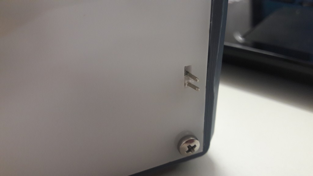
I made up some on the project design.
I added a slider switch to power on/off the CUBE, and added stickers to indicate on which face the CUBE lies on, because I added to code a function that, based on the face that is active, it does something different from the other faces; I also refactored the code for rotations sensing, now there is a better sensibility and less error.
I also modified the Arduino lock-in, now it’s easier and nicer.
The switch
New arduino lock-in: the arduino is screwed into nuts that are in the lasered bottom part
Face stickers; in this case the active face is the third.