Electronics Production
1. Week assignment
Make an in-circuit programmer by milling the PCB, then optionally trying other processes
2. Development Environment
I used Fab Modules (the new version) and Roland V-Panel for Roland SRM-20 milling machine, and Linux Mint for programming the board.
3. Circuit creation
3.1 Board overview
I decided to make the FabOptimus board.
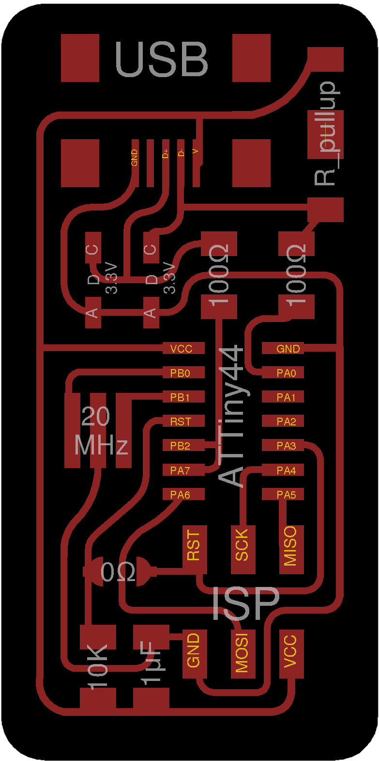
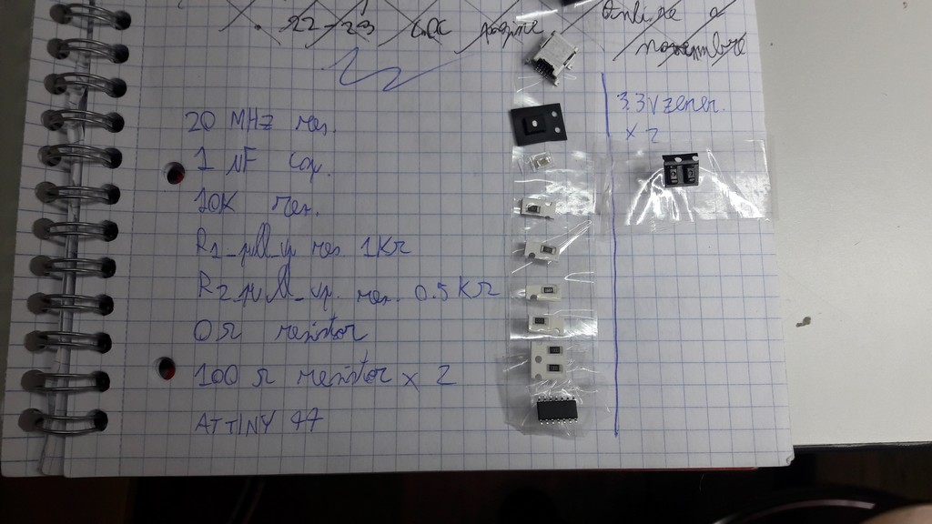
A brief component explanation is present.
- USB: the mini-usb connector, providing power and data transmission
- AT Tiny 44, the IC microcontroller
- ISP: ISP connector
- R_pullup: we used the two series resistor version, due to inventory requirements; the pull-up/pull-down resistors are used for setting the voltage at an input port to V+ / GND, when no other signal is applied to that input port, while still enabling you to change the voltage at that port by either applying another signal to the port or by setting the port as an output.
- 20 MHz resonator: provides clock to the board.
- 3.3 V zener diodes and 100Ω resistors: used for voltage clippers; USB and ATTiny are powered at 5 V, while input pins run at 3.3V, hence the use of voltage clippers.
- 10 kΩ resistor: pull-up resistor for reset pin.
- 1 pf capacitor: used for noise filtering as a decoupling capacitor; a decoupling capacitor’s job is to suppress high-frequency noise in power supply signals. They take tiny voltage ripples, which could otherwise be harmful to delicate ICs, out of the voltage supply. If the power supply very temporarily drops its voltage, a decoupling capacitor can briefly supply power at the correct voltage.
- 0Ω resistor: basically is a short-circuit, and has to be removed to use this board as a programmer.
3.2 Realization
Using FabModules we create the .rml file used by the Roland panel.
There are 2 files: one for the outline and one for the traces:
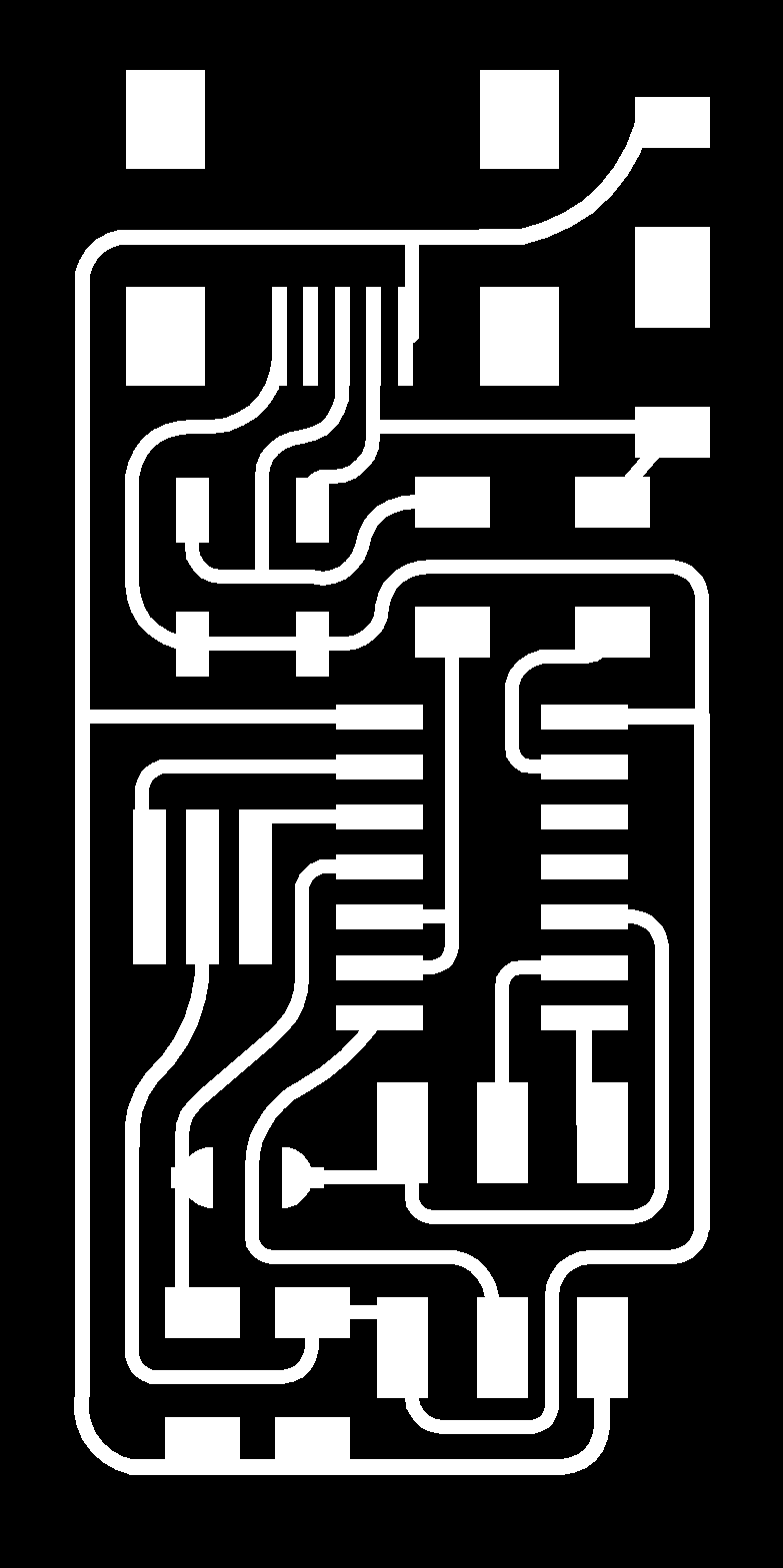
Traces

Outline
We use the 1/64 inch (circa 0.40mm) needle for the traces and 1/32 inch (circa 0.80mm) for cutting the outline.
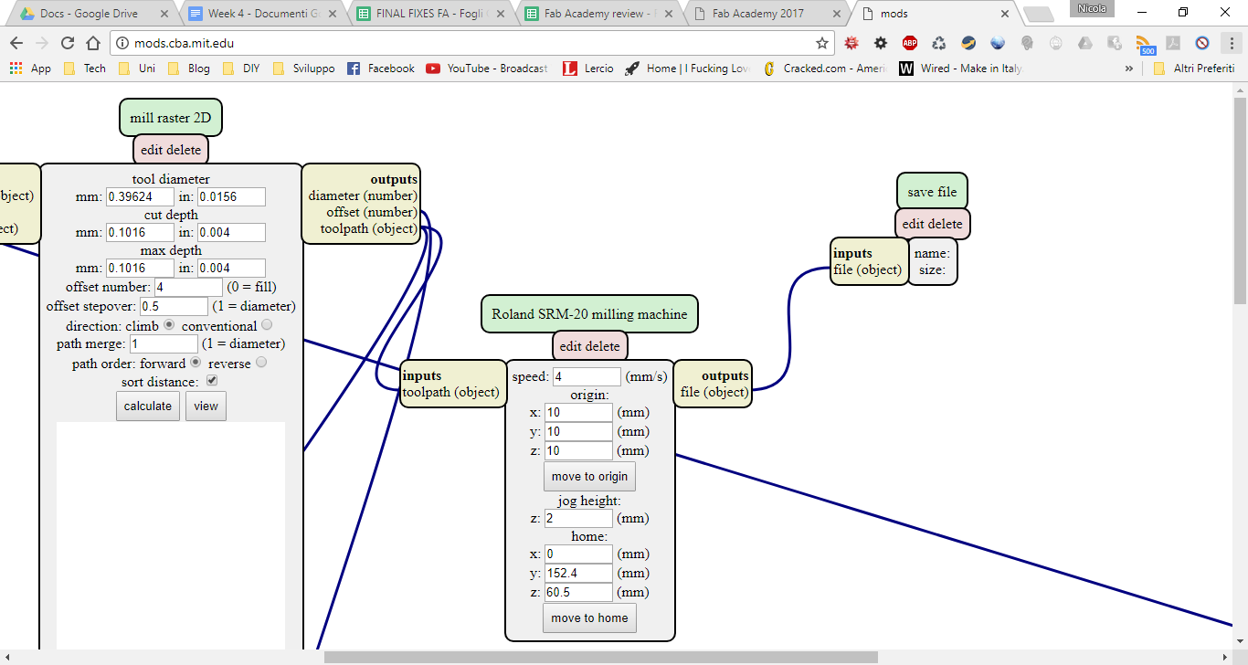
In the fabmodules you need to load the server program for the milling (in my case the module for the roland SRM-20).
The first step is to add the module for file save (Add module -> server module -> file -> save), and link it to the block that calculate the toolpaths (“Roland SRM-20 milling machine”).
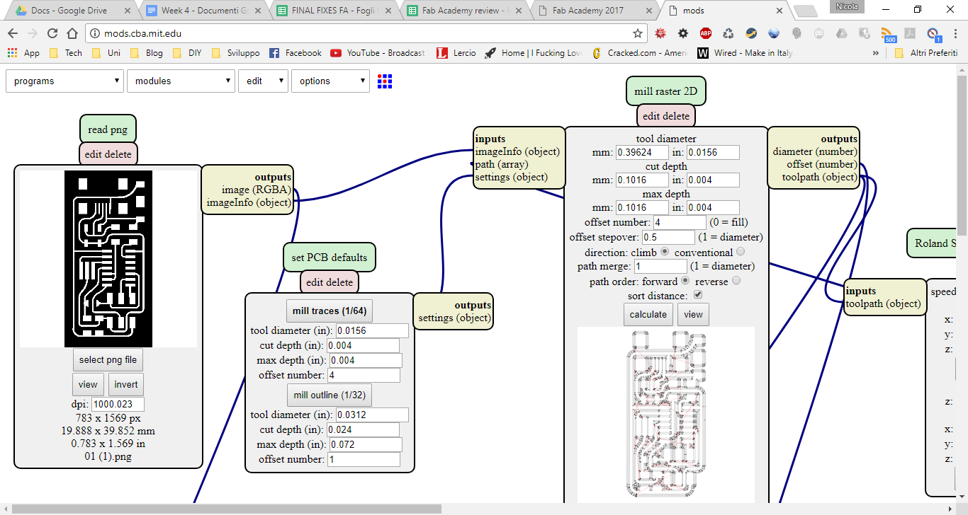
Then in the first block you have to load the png, it must be a black and white image: the parts that are white are left by the mill.
In the next block you have to choose the endmill (1/64 inch or 1/32 inch).
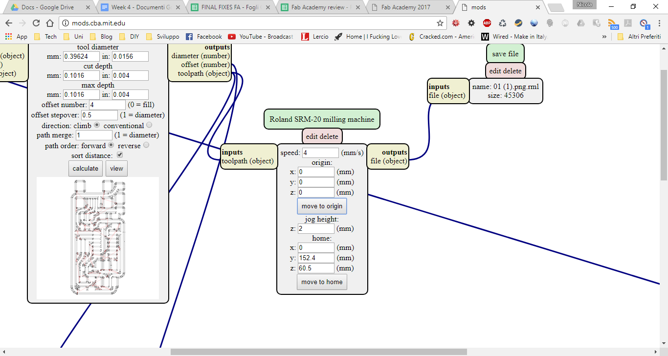
In the block named “mill raster 2D” is possible to set the offset: I used 4 (the offset is the amount of useless copper removed: 0 means that only the tracks are present on the board, it’s slower due to more material removed) and here you can see a preview of the paths.
In the last block (“Roland SRM-20 milling machine”) you set the offset (you need to zero it), the speed (you can leave the default) and where the endmill will home after the job finished.
3.2.1 CNC
First, we put the right needle in the machine. Then we set the X/Y origin, and, as soon as the needle touch the board, the Z origin.
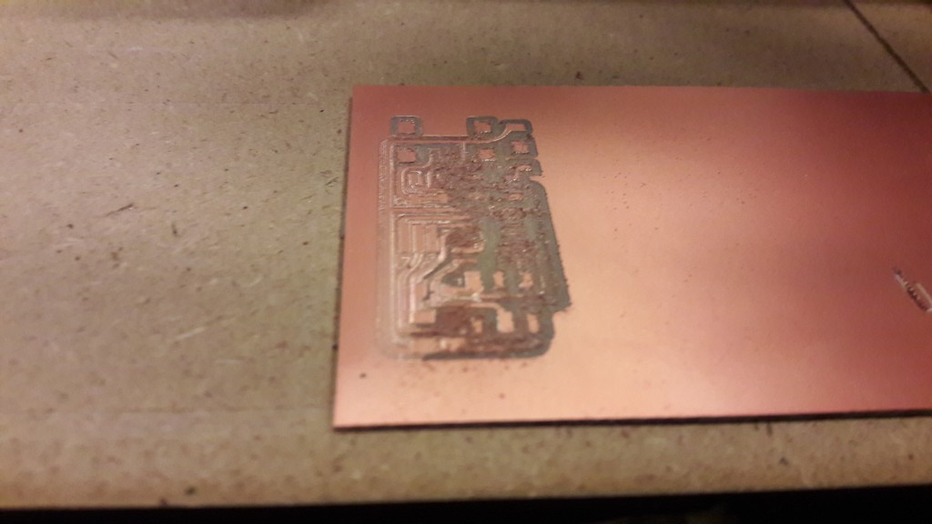
Note: as the needle rotating speed may move the board, we need to fix it to the plane using adhesive tape; I did this error (there was not enough tape) and i broke the needle (photo for reference)
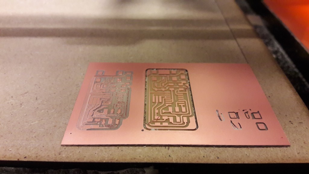
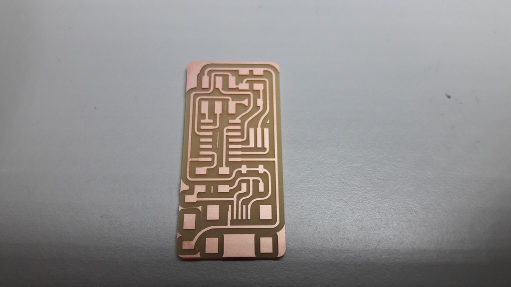
The second try went good (in the right corner is possible to see where the needle broke):
After removing the board is necessary to clean it: it’s possible to use alcohol or water and soap.
3.2.2 Soldering
Then we proceed soldering the components: the first step is to make a material bill for handy access to needed components using tape, then you can start solder.
This is the finished board:
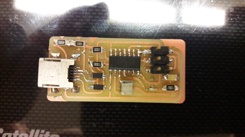
The soldering could have been better, but it’s all working! The problem i had was that there was a trace missing between SPI connector (MISO pin) and AtTiny (I eventually cut off the trace to remove some solder): so i used more solder to connect these two points.
3.2.3 Programming
Using linux terminal, first you install dependencies
sudo apt-get install flex byacc bison gcc libusb-dev avrdude gcc-avr avr-libc libc6-dev
AVRDUDE (AVR Downloader/UploaDEr) is a software that let you manipulate the ROM and EEPROM contents of AVR microcontrollers.
Then you need to download and unzip firmware:
          wget http://academy.cba.mit.edu/classes/embedded_programming/firmware.zip

          unzip firmware.zip

          cd fabISP_mac.0.8.2_firmware
It’s then necessary to edit the Makefile, commenting one line
nano Makefile
Before:
          ...
          #AVRDUDE = avrdude -c usbtiny -p $(DEVICE) # edit this line for your programmer
          AVRDUDE = avrdude -c avrisp2 -P usb -p $(DEVICE) # edit this line for your programmer
          ...
After:
          ...
          AVRDUDE = avrdude -c usbtiny -p $(DEVICE) # edit this line for your programmer
          #AVRDUDE = avrdude -c avrisp2 -P usb -p $(DEVICE) # edit this line for your programmer
          ...
Now you need to plug an already programmed board to the USB and the board to program via ISP to the one connected to pc.
We compile the firmware:
make clean
Terminal output:
rm -f main.hex main.lst main.obj main.cof main.list main.map main.eep.hex main.elf *.o usbdrv/*.o main.s usbdrv/oddebug.s usbdrv/usbdrv.s
make hex
Terminal output:
          avr-gcc -Wall -Os -DF_CPU=20000000	-Iusbdrv -I. -DDEBUG_LEVEL=0
          -mmcu=attiny44 -c usbdrv/usbdrv.c -o usbdrv/usbdrv.o
          avr-gcc -Wall -Os -DF_CPU=20000000	-Iusbdrv -I. -DDEBUG_LEVEL=0
          -mmcu=attiny44 -x assembler-with-cpp -c usbdrv/usbdrvasm.S -o usbdrv/usbdrvasm.o
          avr-gcc -Wall -Os -DF_CPU=20000000	-Iusbdrv -I. -DDEBUG_LEVEL=0
          -mmcu=attiny44 -c usbdrv/oddebug.c -o usbdrv/oddebug.o
          avr-gcc -Wall -Os -DF_CPU=20000000	-Iusbdrv -I. -DDEBUG_LEVEL=0
          -mmcu=attiny44 -c main.c -o main.o
          avr-gcc -Wall -Os -DF_CPU=20000000	-Iusbdrv -I. -DDEBUG_LEVEL=0
          -mmcu=attiny44 -o main.elf usbdrv/usbdrv.o usbdrv/usbdrvasm.o usbdrv/oddebug.o
          main.o
          rm -f main.hex main.eep.hex
          avr-objcopy -j .text -j .data -O ihex main.elf main.hex
          avr-size main.hex
          text	data	bss	dec	hex	filename
          0	2020	0	2020	7e4	main.h
          make fuse
          make program
If the output of last command ends with “avrdude done. Thank you.” the programming went fine.
In depth:
- make clean deletes eventually present object and hex files: it cleans the directory
- make hex builds the .hex file: an .hex files is a format used to store machine low-level code in hexadecimal form
- make fuse build the fuses: the fuses are some programmable flash memory location that control the chip behaviour (like the CPU speed) kept separated from the user program space, so the program you are running can’t mess anything on the board
- make program pushes via the ISP the hex and the fuses on the board
If all of these commands went good, the programming went good. Now you need to de-solder the 0Ω resistor.
To see if the board is working you can list usb device on you pc:
lsusb
If it’s all good you can see in the command output something like this:
Bus 002 Device 004: ID 1781:0c9f Multiple Vendors USBtiny
4. References
5. Files
FabOptimus files, .png and .rml - .zip