Mechanical Design
1. Week assignment
- design a machine (mechanism+automation), including the end effector
- build the passive parts and operate it manually
- document the group project and your individual contribution
2. Development Enviroment
This week I mainly used SolidWorks.
3. The design
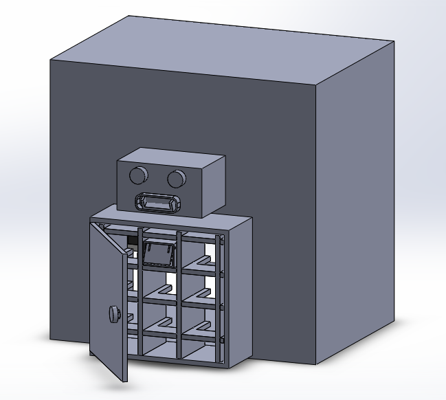
With my colleague Alessandro we designed the ScrewBot: it’s made of 9 drawers with different screws in each one: each drawer is then selected by a “hand”, and took up: a servo inclines the drawer and let the screws fall off.
Our machine will have 4 axis: X,Y and Z controlled by 3 stepper motor, and the inclination of the hand, controlled by a servo motor.
The Z axis will move the frame containing the X-Y axis; then a drawer will be choose: we take the drawer up above and with the servo we can empty it.
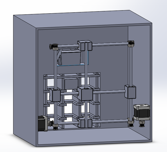
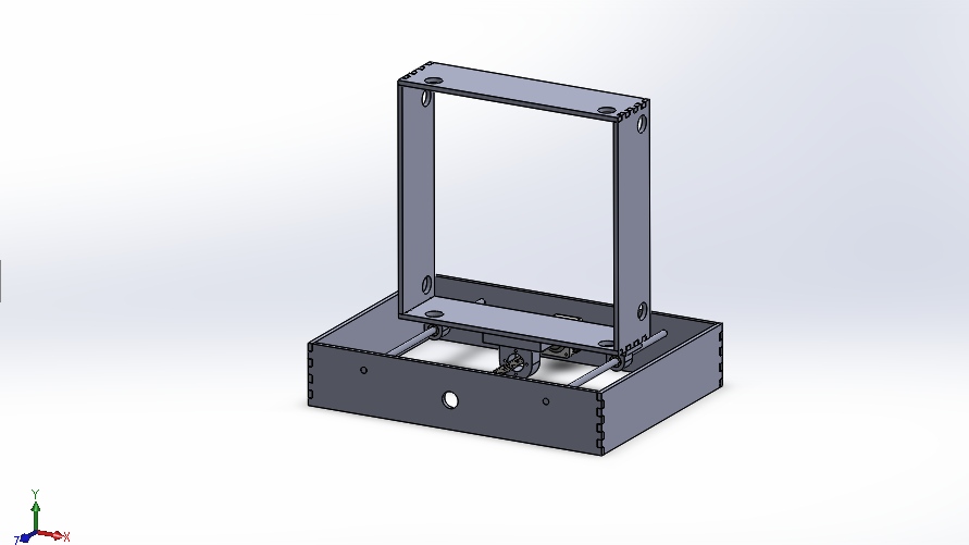
This is the main frame and the bigger part of design, done by my colleague Alessandro.
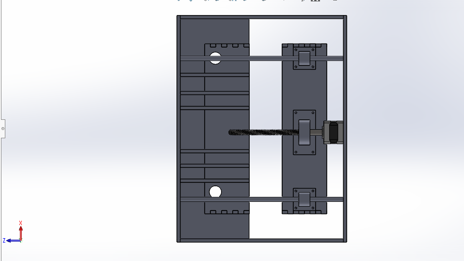
The above design is the for X and Y axis.
I designed the base for the Z axis.
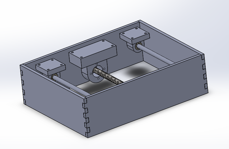
The main components of this design are:
- A nema 17 stepper motor
- A threaded rod
- Two linear rods
- 2 supports for the linear rods
- A support for the threaded rod
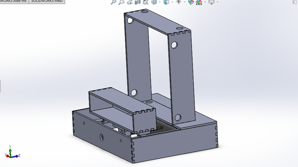 Here’s with the frame designed by Alessandro (I couldn’t upload it on sketchfab because the file is too big)
All the frames are made of plywood, cutted with the Trotac Lasercut we have in lab.
The two linear rods will be glued to the wood, and the stepper motor will be screwed to the wood with passing-through screws.
The supports have a linear bearing in it, all 3d printed.
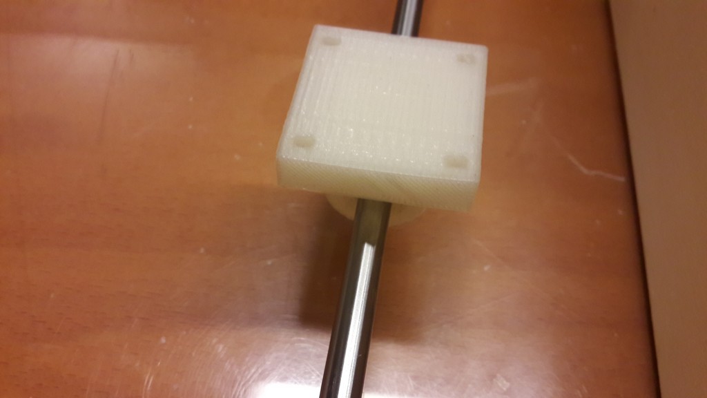
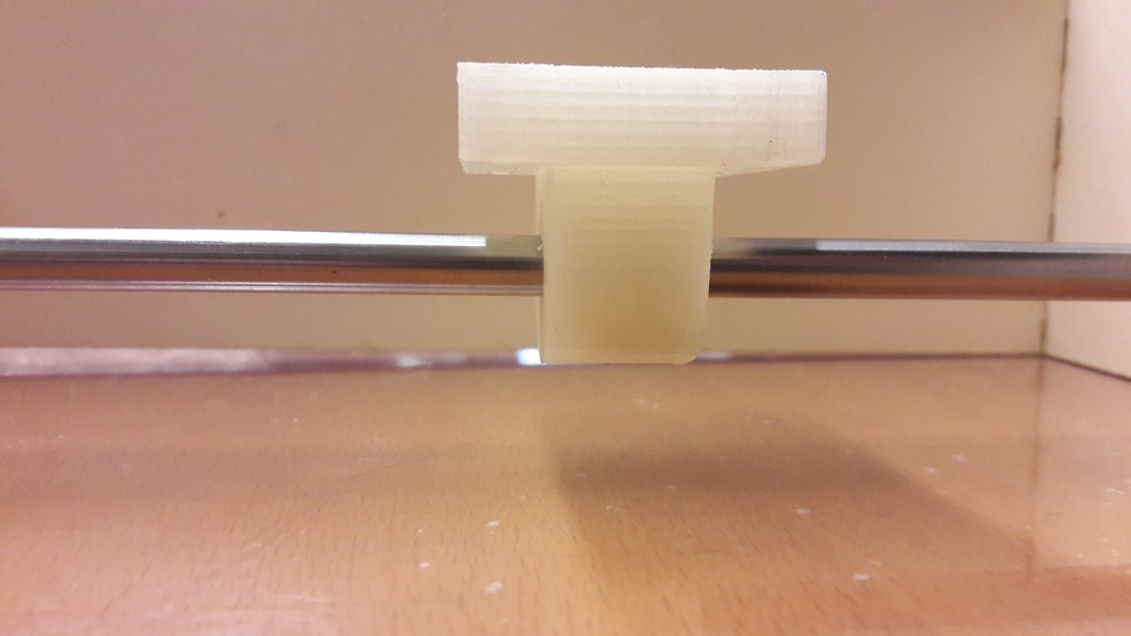 Linear rod with supports
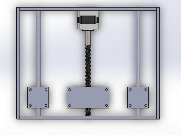
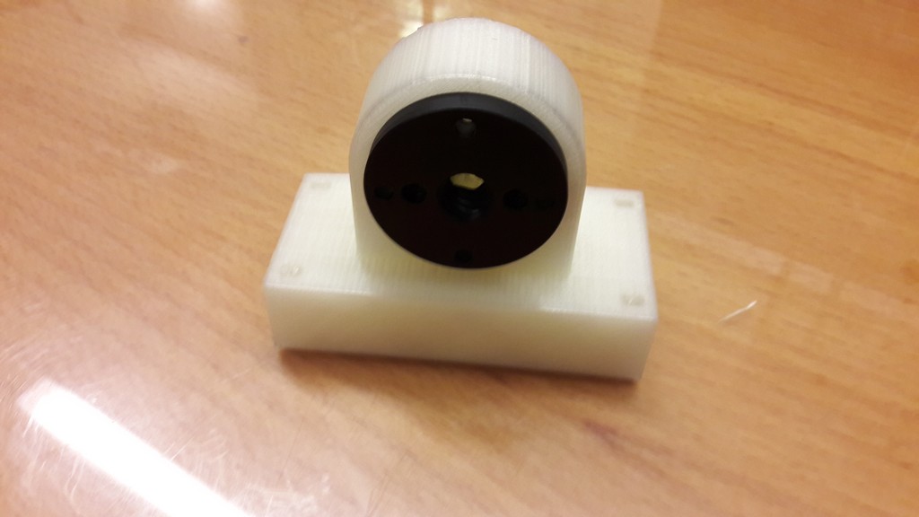 Support for the threaded rod with the guide for it
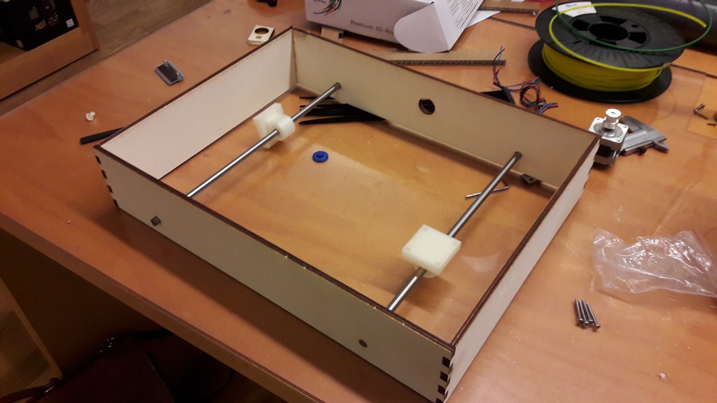 The ongoing assembly
When then we placed the frame on its support we notice a design problem: when we try to move the frame it’s too heavy and it won’t slide on the bearings.
This is due to the fact that the frame for X-Y axis is too heavy: it would have need a larger base and two bearings on each linear rods.
Due to the fact the main X-Y frame was already built, we decided to keep it still and to move the drawers.
The frame is glued and supported by “triangles” used as sustains, while another box let the drawers move.
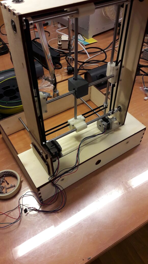 The building is in progress…
Continue on week 11.
Link to group documentation