Machine Design
1. Week assignment
- automate your machine
- document the group project and your individual contribution
2. Development Enviroment
TThis week I mainly used Arduino IDE.
3. The building
I started lasering the frames I designed on week 9. Then here came a problem: we had some material missing due to expedition delay, so my colleague Alessandro designed a different system to move the drawers.
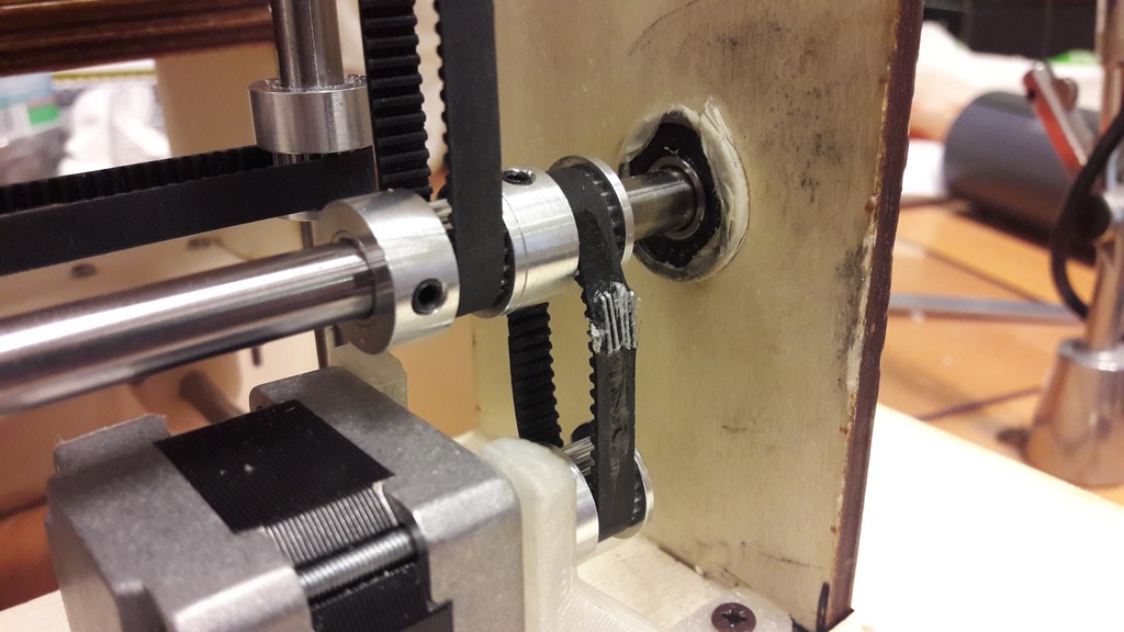
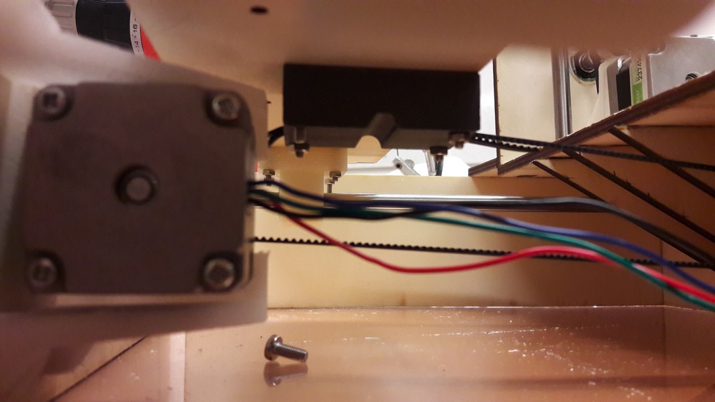
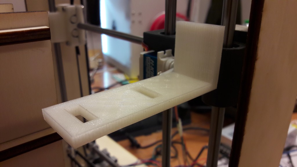
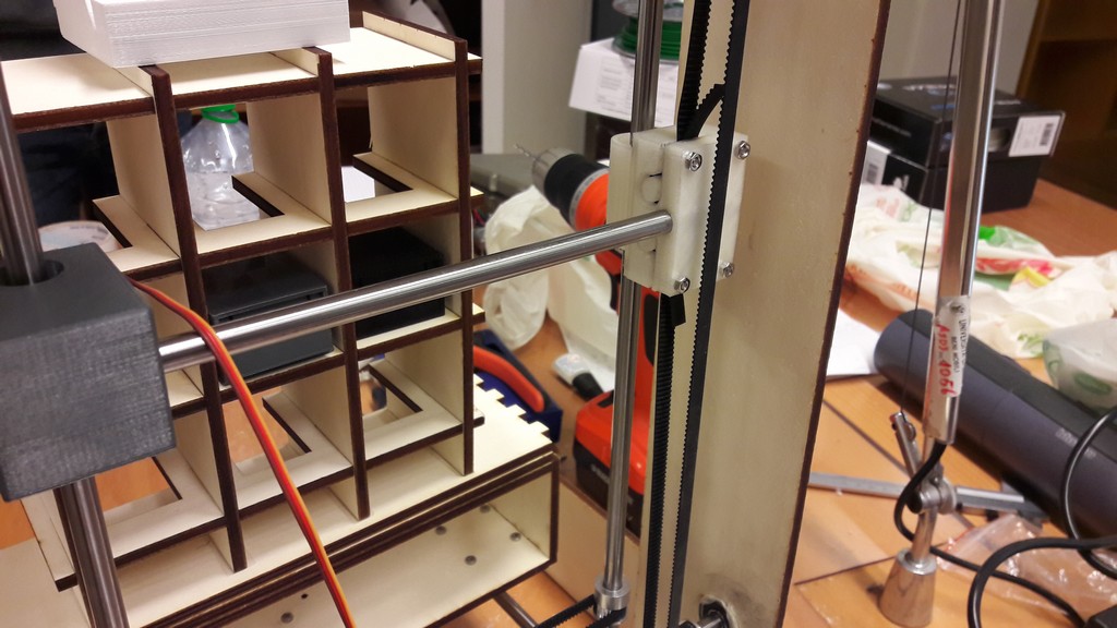
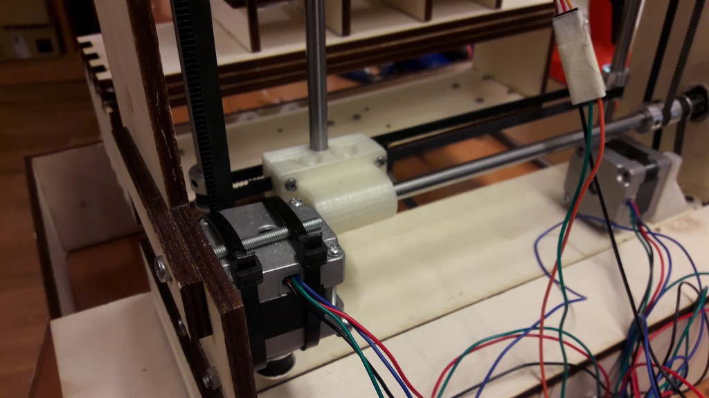
It uses a 3D printed support for a nema 17, a belt block and linear bearing with a 3d support.
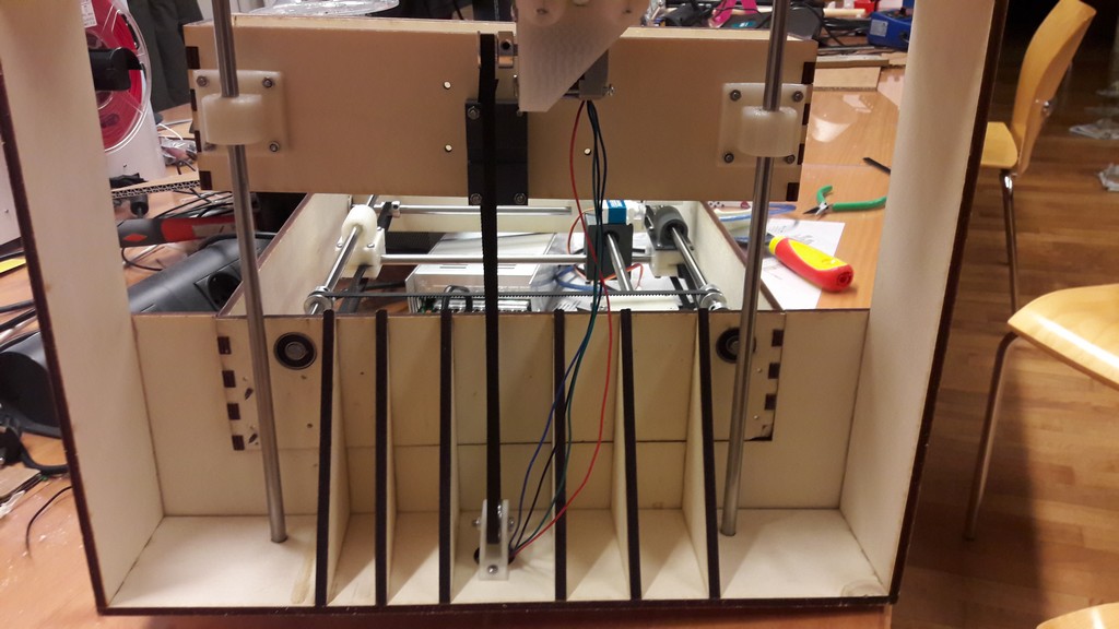
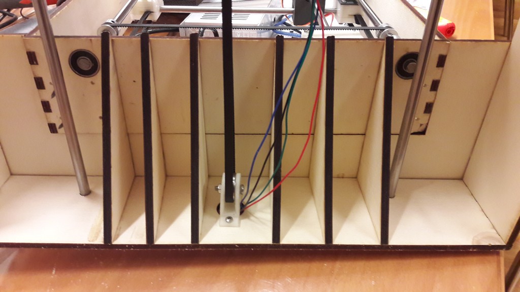 View from below
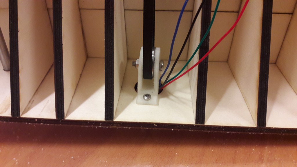 The linear bearing guiding the belt
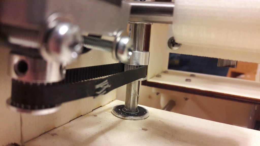
A big problem we had was making closed belt loops without blocks for them:
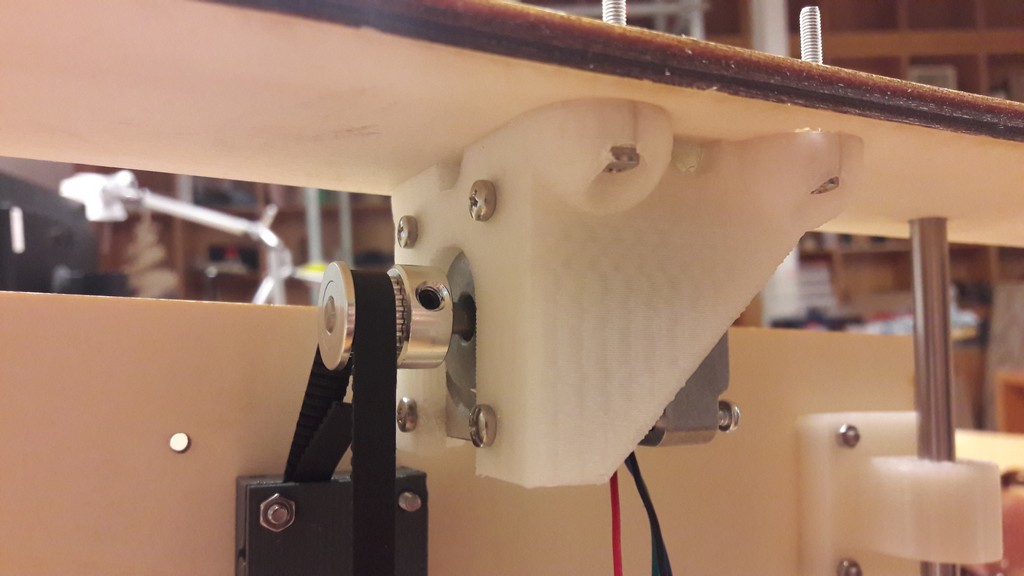 The X pulley and belt
 The Y pulley and belt
Not having closed belts, we had to find some way to close them: on first base, we tried to sew them, but they were too loose.
We then tried to heat them (like a shrink tube, both with a lighter and a soldering iron), but the plastic of which they are made makes impossible to join two ends.
The solution, as ugly as it seems, was using a stapler and a glue: we stapled the two ends and used some hot glue on the outside to be sure that the belts won’t broke.
They, however, loses some steps while turning.
Note: to use belts with motor pulley the have to be as stretched as it is possible; so to mount them you need to close the belt, insert the motor pulley, then fix the motor, stretching the belt.
I personally found this difficult, as they broke lot of times.
We did not have this problem with Z axis, having a belt block.
We then moved on to mount the drawers sustain (the box where it stands) and noticed a big problem: the Z axis and the sustain are way too short!
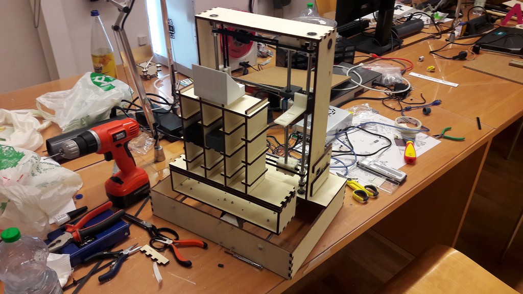
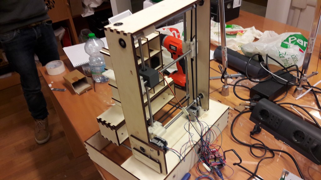
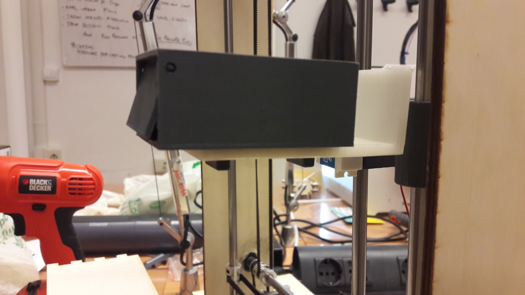
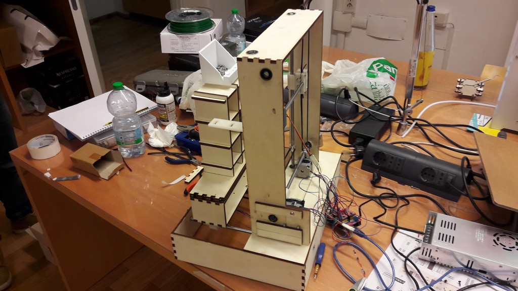
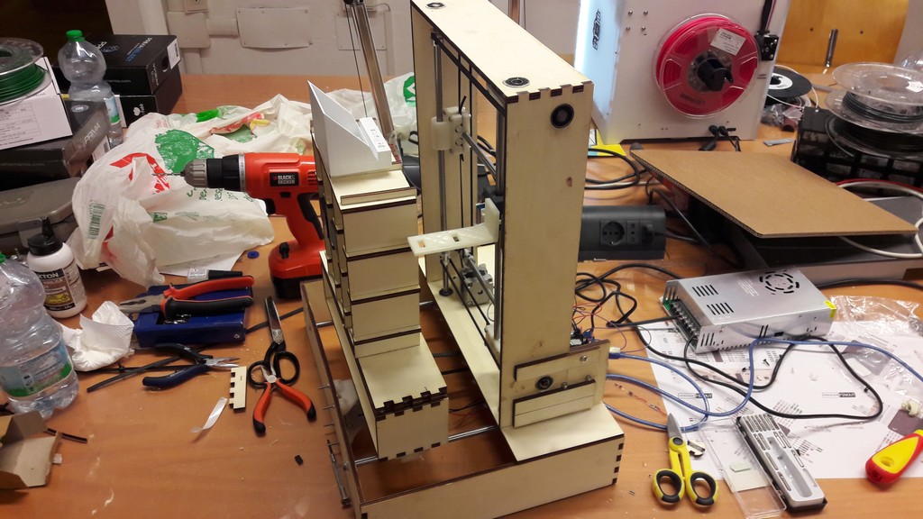 The finished machine!
To automate the machine, we use 3 stepper motors and a servo.
A stepper motor is a brushless DC motor, with two windings (acting like magnets) inside it (at least in bipolar motors) that let a gear inside rotate depending on which one is on.
Source: Wikimedia
We used Jameco nema 17 motors. (nema 17 stands for the standard of distance between the fixing screw in the motor)
I soldered the motor wires on a female 4x1 header.
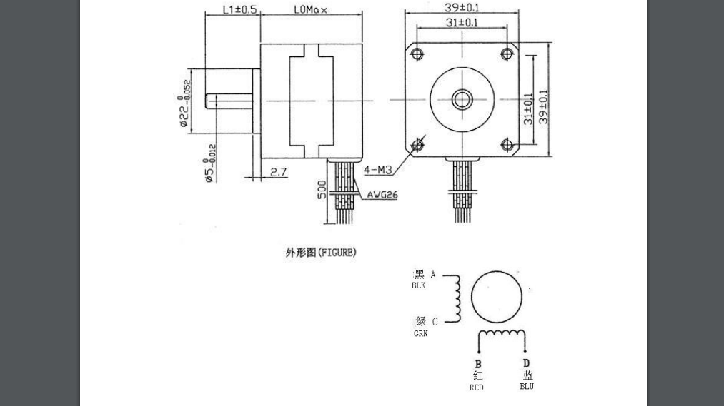
As you can see from its datasheet the color for the two windings are red-blue and black-green.
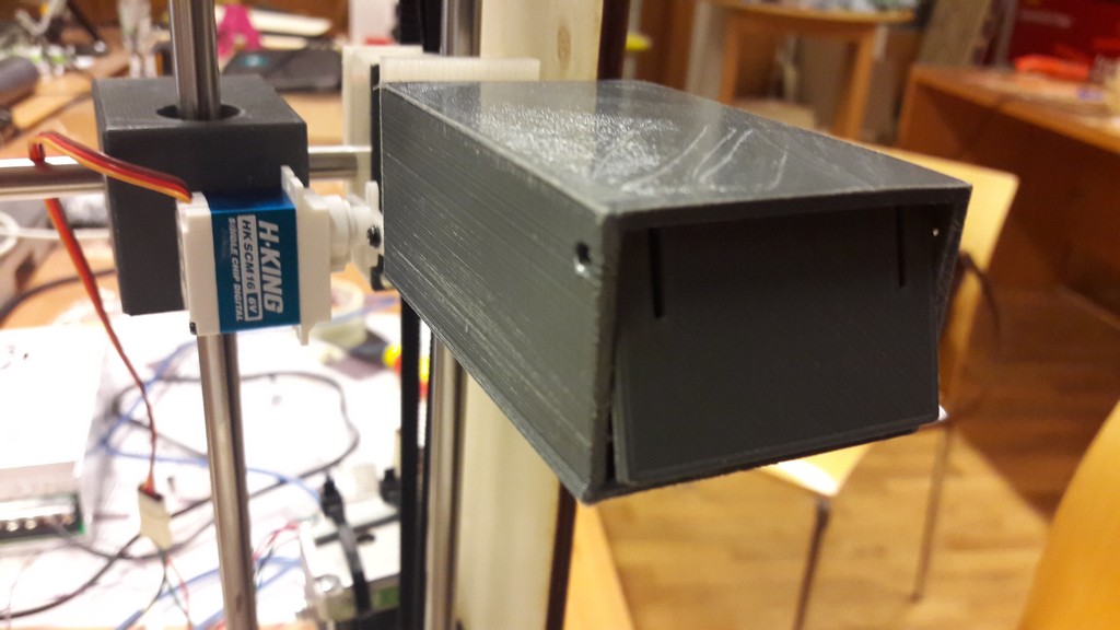
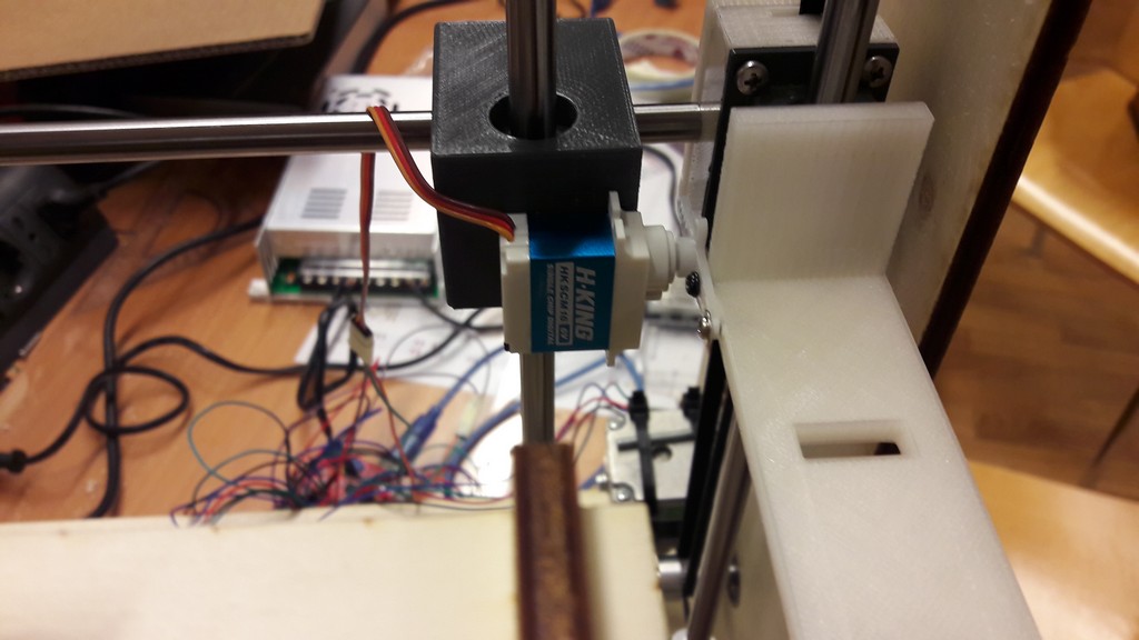
A servomotor, instead, is an actuator with precise control over the angular position. We used this to incline the drawer, to empty it.
All of them will be controlled by GRBL, using an Arduino Duemilanove and a CNC shield.
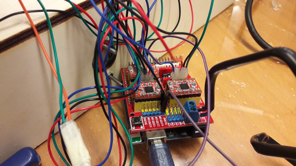 The wiring detail. As you can see I used some hot glue to give more stability on motors connector.
As from GRBL GitHub page:
Grbl is a no-compromise, high performance, low cost alternative to parallel-port-based motion control for CNC milling. It will run on a vanilla Arduino (Duemillanove/Uno) as long as it sports an Atmega 328.
The controller is written in highly optimized C utilizing every clever feature of the AVR-chips to achieve precise timing and asynchronous operation. It is able to maintain up to 30kHz of stable, jitter free control pulses..
It accepts standards-compliant g-code and has been tested with the output of several CAM tools with no problems. Arcs, circles and helical motion are fully supported, as well as, all other primary g-code commands. Macro functions, variables, and most canned cycles are not supported, but we think GUIs can do a much better job at translating them into straight g-code anyhow..
So using GRBL the only thing you have to write is your gcode, because the underlying control layer is managed by GRBL and it’s completely transparent for the user.
The CNC shield is a board developed for Arduino, GRBL-compatible, that manages the motors. It has 4 axis - X Y Z and A - and every axis need a driver for the motor. Every driver has a potentiometer on it: it regulates the current flowing in the motor. To attach the motor to the CNC shield there is a four pin header for the 2-wire couples of the motor: inverting which couple is connected on the shield you invert the rotation of the motor (going forward for positive value in gcode or backward).
We used a porting of GRBL that let you use the servo with special gcode instructions, as it’s not been supported on official grbl release.
The signal pin on the servo is connected to Arduino D11 pin, corresponding to Z- endstop pin on CNC shield.
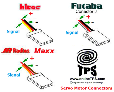 Color codes for servo.
You need to configure GRBL: we modified only value for steps/mm for each axis.
As from their documentation:
Grbl needs to know how far each step will take the tool in reality. To calculate steps/mm for an axis of your machine you need to know:.
- The mm traveled per revolution of your stepper motor. This is dependent on your belt drive gears or lead screw pitch.
- The full steps per revolution of your steppers (typically 200)
- The microsteps per step of your controller (typically 1, 2, 4, 8, or 16). Tip: Using high microstep values (e.g., 16) can reduce your stepper motor torque, so use the lowest that gives you the desired axis resolution and comfortable running properties.
The steps/mm can then be calculated like this:
steps_per_mm = (steps_per_revolution*microsteps)/mm_per_rev
In our case:
- our steppers have 200 steps per revolution
- 2 mm travelled for every revolution, depeding on our belt
- no microsteps: so 1 in the above calculation
The automation of our machine consists in 3 types of movement: one of the drawer in the X-Y axis, one for the drawers holder in the Z axis and one for inclining the drawer using the servo motor.
We used this gcode instructions, sent by Universal Gcode Sender, as hinted by GRBL (you could use any serial monitor talking to GRBL with 115’200 baud rate).
It’s also possible to write a gcode file and send it to the machine.
G0 - rapid linear move
syntax : G0 Xnn Ymm
move to nn, mm position
G1 - linear move
syntax: G1 Znn Fmm
move to position nn with feed rate mm
Strangely, our Z-axis sometimes moves only forwards and only with this instruction (with feed rate 5), and it can’t come back. We have really no idea on what’s going on here!
M03 - servo control
syntax: M03 Sxxx, xxx between 0 and 255
Send the PWM pulse on the servo, controlling its inclination: 0 means 0°, 255 means 180°, so one unit here is equivalent to circa 0.70°
M05 - servo home
syntax:M05
Set the servo on 0°
UniversalGCodeSender screenshot and use:
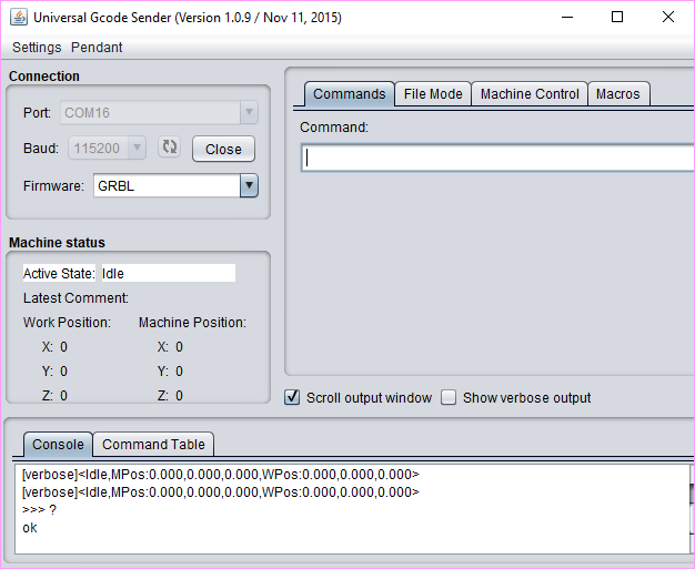
Connection, remember to set 115’200 baud

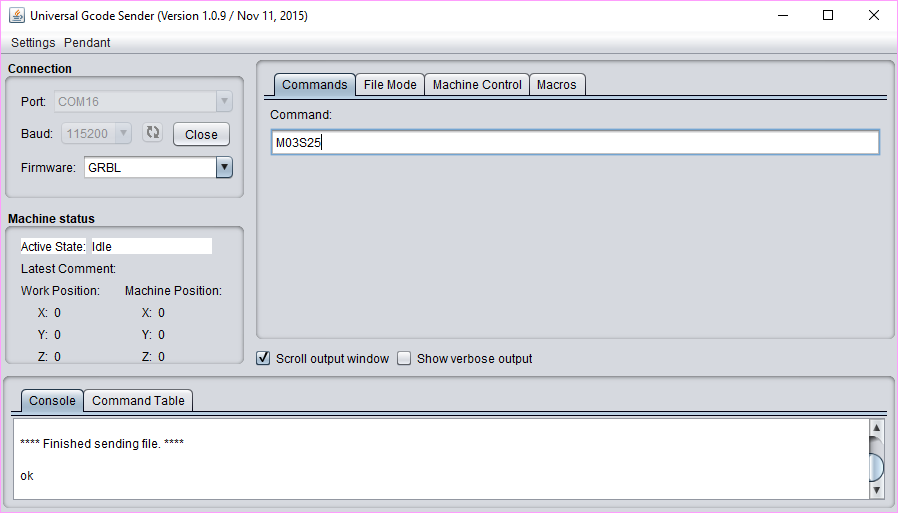
Sending some commands
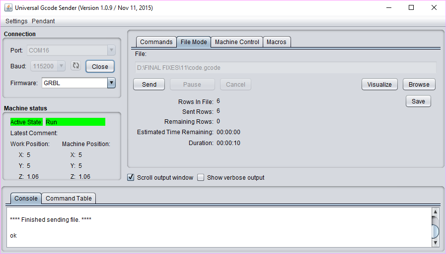
We also writed a simple gcode cambining the command necessary for the machine moving
G0X5Y5
G1Z1.5F10
M03S25
M05
G1Z0F5
G0X0Y0
And finally, here’s some picture of our machine:
And here some videos of the various movements:
Command sent: G0X5Y5 - G0X0Y0
Command sent: M03S25 - M05
Command sent: G1Z1.5F10 G1Z0F5
Link to group documentation