Input Devices
1. Week assignment
Measure something: add a sensor to a microcontroller board that you have designed and read it
2. Development Enviroment
This week I used Arduino IDE, Eagle, VPanel for Roland SRM-20 and FabModules.
3. The Board design
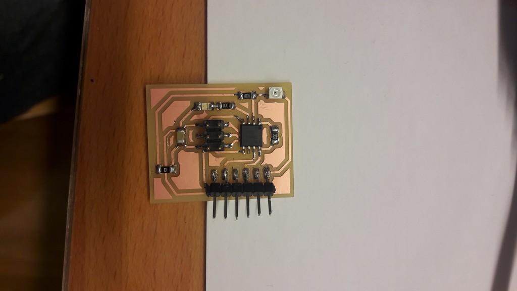
I modified the Neil’s photosensor board.
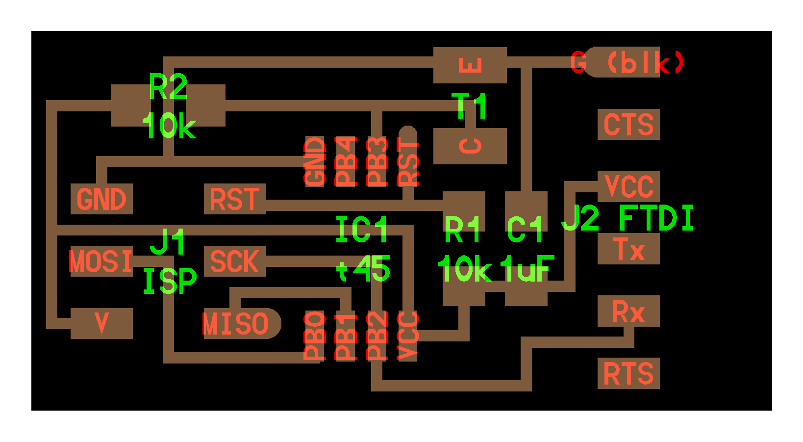 Original board
I added a led because I wanted an output directly on the board, not only on the serial bus.
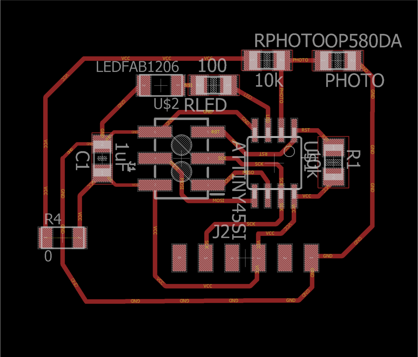
Overview of components:
- Attiny45V: the microcontroller
- 6-pin ISP connector: for programming the board
- FTDI header: powers the board and allows board to talk to computer
- C1 - 1u: capacitor between VCC and GND for stabilizing voltage ripples that could rise. The nearer is to the sources, the better it is.
- R1 - 10k: pull-up resistor on RST pin (more on here)
- OP580DA: is an NPN silicon phototdarlington; it’s a transistor where the junction is exposed to the ambient light: this exposition change the current and therefore the resistance value
- RPHOTO - 10K: used a voltage divider for the OP580DA (see >Week 4, same as thermistor)
- RLED - 100: used as current limiter for LED
- R4 - 0: used as jumper
- LED
There is no external crystal: I’ll be using internal 8 MHz clock.
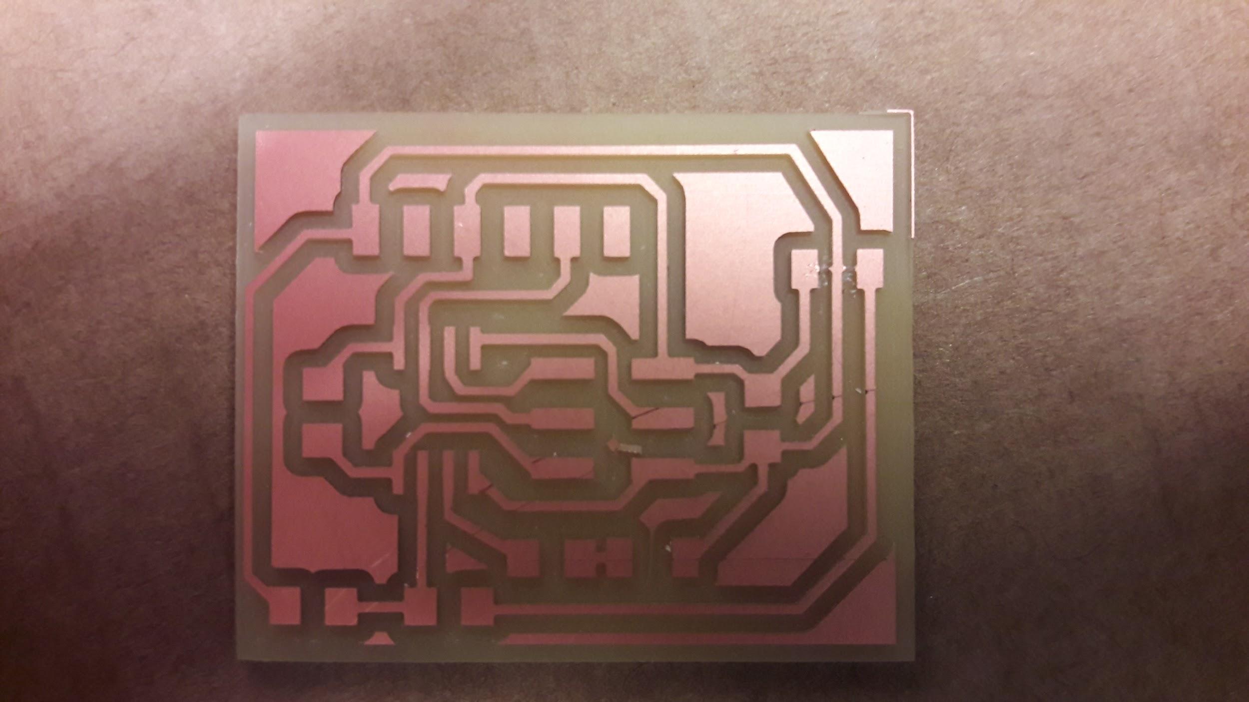
Then I proceeded to make the board:
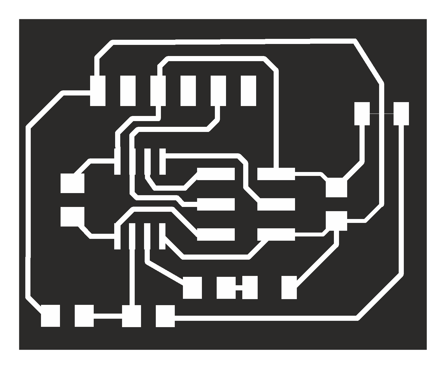
Traces

Outline
Then using fabmodules i made the Roland files and milled the board:
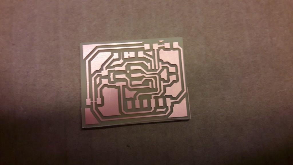
At this time I noticed the thin white line between the 0 ohm jumper (down left corner): it’s an error of the export from Eagle. I had to cut it by hand with a cutter.
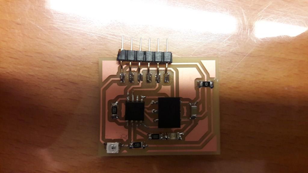
 (Upper right corner, now fixed!)
And here’s the board with all the components soldered:
4. The Programming
I used Arduino IDE: first you need to burn the bootloader, after choosing the AtTiny45 (see 3. Arduino IDE, week 10)
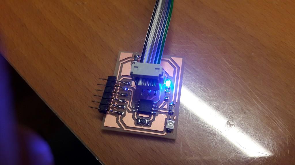
I tried the basic blink sketch to see if the board is working, and it is:
Then I moved on to use the photoresistor:
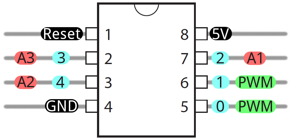
            int led = 4;
            int sensor = 3;
            void setup() {
              // put your setup code here, to run once:
              pinMode(led, OUTPUT);
              pinMode(sensor,INPUT);
            }

            void loop() {
              if(analogRead(sensor) < 500)
              digitalWrite(led,HIGH);
              else
              digitalWrite(led,LOW);
            }
I define the pin with the led (4) and the sensor (3), using this reference
Then if the ADC result is lower with respect of a certain threshold (in this case 500), the LED is powered off.
Here’s in action:
Week 13 - Photoresistor from Nicola Giannelli on Vimeo.
I then moved on using the serial. I noticed that I used a wrong header for the FDTI: i desoldered the old one and added this:
I used this sketch:
            #include <SoftwareSerial.h>
            SoftwareSerial mySerial(rx,tx);

            const int rx=0;
            const int tx=2;
            int led = 4;
            int sensor = 3;
            int value;


            void setup() {
              // put your setup code here, to run once:
              pinMode(rx, INPUT);
              pinMode(tx, OUTPUT);
              pinMode(led, OUTPUT);
              pinMode(sensor,INPUT);
              mySerial.begin(9600);
              digitalWrite(led,HIGH);
              delay(500);
              digitalWrite(led,LOW);
              delay(500);
            }

            void loop() {
              if (mySerial.available()) {
                digitalWrite(led,HIGH);
                value=analogRead(sensor);
                mySerial.print(value);
                mySerial.println();
              }
            }
You have to define the RX pin as input and TX as output as it won’t work without this definition.
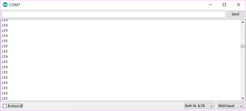
Using IDE serial monitor I then read sensor value.
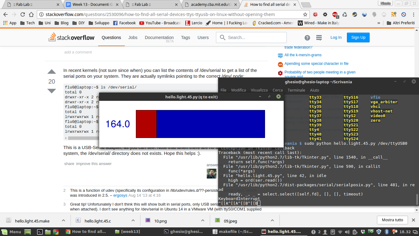
I then used the file .c and make file from the archive, and the provided python script. It's all working.
5 - Files
Board files and sketch - .zip
Update
It's possible to find more work about this week on the final project page in the related development section